EP0844026B1 - Elektrostatiche Trennvorrichtung zur Sortierung triboelektrisch aufgeladener Stoffgemische - Google Patents
Elektrostatiche Trennvorrichtung zur Sortierung triboelektrisch aufgeladener Stoffgemische Download PDFInfo
- Publication number
- EP0844026B1 EP0844026B1 EP97117099A EP97117099A EP0844026B1 EP 0844026 B1 EP0844026 B1 EP 0844026B1 EP 97117099 A EP97117099 A EP 97117099A EP 97117099 A EP97117099 A EP 97117099A EP 0844026 B1 EP0844026 B1 EP 0844026B1
- Authority
- EP
- European Patent Office
- Prior art keywords
- electrodes
- separating
- electrostatic
- separating apparatus
- separation
- Prior art date
- Legal status (The legal status is an assumption and is not a legal conclusion. Google has not performed a legal analysis and makes no representation as to the accuracy of the status listed.)
- Expired - Lifetime
Links
- 239000000203 mixture Substances 0.000 title claims abstract description 6
- 238000000926 separation method Methods 0.000 title claims description 35
- 239000000463 material Substances 0.000 title claims description 7
- 239000000126 substance Substances 0.000 claims abstract description 3
- 239000002801 charged material Substances 0.000 claims 1
- 230000003068 static effect Effects 0.000 claims 1
- 239000000047 product Substances 0.000 description 11
- 239000002245 particle Substances 0.000 description 8
- 239000008187 granular material Substances 0.000 description 3
- 229920003023 plastic Polymers 0.000 description 3
- 239000004033 plastic Substances 0.000 description 3
- 229910052500 inorganic mineral Inorganic materials 0.000 description 2
- 239000011707 mineral Substances 0.000 description 2
- 239000002994 raw material Substances 0.000 description 2
- 210000002105 tongue Anatomy 0.000 description 2
- 229920000426 Microplastic Polymers 0.000 description 1
- 239000007795 chemical reaction product Substances 0.000 description 1
- 239000004020 conductor Substances 0.000 description 1
- 230000003111 delayed effect Effects 0.000 description 1
- 230000005684 electric field Effects 0.000 description 1
- 238000009434 installation Methods 0.000 description 1
- 238000004064 recycling Methods 0.000 description 1
- 230000001105 regulatory effect Effects 0.000 description 1
- 239000007787 solid Substances 0.000 description 1
- 239000012798 spherical particle Substances 0.000 description 1
Images


Classifications
-
- B—PERFORMING OPERATIONS; TRANSPORTING
- B03—SEPARATION OF SOLID MATERIALS USING LIQUIDS OR USING PNEUMATIC TABLES OR JIGS; MAGNETIC OR ELECTROSTATIC SEPARATION OF SOLID MATERIALS FROM SOLID MATERIALS OR FLUIDS; SEPARATION BY HIGH-VOLTAGE ELECTRIC FIELDS
- B03C—MAGNETIC OR ELECTROSTATIC SEPARATION OF SOLID MATERIALS FROM SOLID MATERIALS OR FLUIDS; SEPARATION BY HIGH-VOLTAGE ELECTRIC FIELDS
- B03C7/00—Separating solids from solids by electrostatic effect
- B03C7/006—Charging without electricity supply, e.g. by tribo-electricity or pyroelectricity
-
- B—PERFORMING OPERATIONS; TRANSPORTING
- B03—SEPARATION OF SOLID MATERIALS USING LIQUIDS OR USING PNEUMATIC TABLES OR JIGS; MAGNETIC OR ELECTROSTATIC SEPARATION OF SOLID MATERIALS FROM SOLID MATERIALS OR FLUIDS; SEPARATION BY HIGH-VOLTAGE ELECTRIC FIELDS
- B03C—MAGNETIC OR ELECTROSTATIC SEPARATION OF SOLID MATERIALS FROM SOLID MATERIALS OR FLUIDS; SEPARATION BY HIGH-VOLTAGE ELECTRIC FIELDS
- B03C7/00—Separating solids from solids by electrostatic effect
- B03C7/02—Separators
- B03C7/12—Separators with material falling free
Definitions
- the invention relates to an electrostatic free fall separator mixtures of substances, e.g. for the separation of mineral raw materials or for Separation of plastic mixtures.
- US A 2782923 describes an apparatus for processing ore Separator is an electrostatic free-fall separator that is also a tube electrode in the manner of a tubular gate.
- Reverse polarity electrodes is a single voltage source connected so that there is a voltage gradient between these electrodes is available.
- To influence the separation result is in the middle of the separation space another electrode of the same type in the direction of fall of the material to be separated Arranged type, whose potential can be regulated via a potentiometer, which is connected to the same voltage source is connected, can be varied.
- One electrostatic separation is usually sufficient Not separator to selectively split into two components with satisfactory To separate purity. It is necessary to stage the products in two or more stages To separate plants. There are large funding paths between levels too overcome, the space requirement is considerable and the investment costs increase increasing number of stages.
- a disadvantage of such multi-stage systems that in the Rule two and, in special cases, three or more separators, is that horizontal funding bodies, e.g. Screws, chain conveyors be required to switch intermediate fractions from one separator to the other to be able to promote others. In a system with two separators, there are two Horizontal conveyor required. The amount is increased by the horizontal conveyor circulating material significantly increased. This is essential with two Disadvantages connected.
- the residence time of the goods increases Plant, which can lead to an increased discharge of the charged particles.
- Discharge can occur through charge exchange between the charged particles take place, but also by contact of the particles with the wall materials of the Conveyor housing.
- the other disadvantage of the increased circulation quantity is in that the setting of the separation equilibria is delayed. It is therefore the To solve the task, the generic free fall separator for electrostatic To further develop the separation so that the space requirement is the same or higher Separation performance drops and a stable operating condition is reached more quickly.
- the electrodes receive their electrical potential via two separate voltage sources of different polarity.
- One voltage source supplies a positive voltage against the potential earth and the other a negative voltage against the potential earth, whereby the potential difference against earth is zero in the middle of the separator.
- the great advantage of this arrangement is that for a given field strength in the separation space and given the dimensions, the field strength between electrodes and housing drops to half the value, e.g. from the maximum permitted value of 2 KV / cm according to the DIN standard to only 1 KV / cm.
- the voltage distribution according to the invention thus makes it possible to halve the safety distances between electrodes and housing with otherwise the same separation performance. This alone can reduce the volume of a separator from 8.6 to 3.8 m 3 for a throughput of 1 t / h, for example.
- the Increase the field strength in the separation space without at the same time the distances to the housing need to increase. Because the higher field strength the particles in the field better can be deflected, the fall height can be reduced and thus the height can be saved be, or it can also coarser granules with given dimensions be separated.
- a surface charge density is namely one spherical particles with radius r contribute to the deflection in the electric field constant field strength inversely proportional to the radius of the particle, i.e. at doubling the particle radius reduces the deflection by half. This, in turn, as far as the voltage resistance of the separator allows, compensate by doubling the field strength. With given dimensions a separator becomes the separation due to the voltage distribution allows coarser granules. This is particularly interesting when separating of plastic granules as part of the recycling of plastics.
- the volume of the separator system for an installation with two separation stages can also be reduced. This is achieved by arranging two separation rooms in a row so that the electrode pairs, which each form a separation space, are close together lie and are separated from each other only by a non-conductive wall. there the electrodes of the same polarity are in alignment.
- everyone who Separation rooms are with a separation room inlet in the usual design and at the lower end the drop distance with the known good discharges for medium goods, positively loaded goods and negatively charged goods.
- each of the other good discharges can be chosen with one of the two Separation room inlets are connected via a conveyor unit.
- the promotion expediently takes place pneumatically via a conveying fan or via a Elevator.
- the separator system volume can be reduced from approx. 22 m 3 to 10 m 3 for a throughput of 1 t / h and two separation stages.
- both features of the invention are combined with one another when building a plant with two separators and a predetermined grain size of a granulate to be separated, in the case of a 1 t / h plant the volume of the separator plant can be reduced from approx. 22 m 3 to approx. 6 m 3 . This corresponds to almost only a quarter of the volume of the system according to the state of the art.
- Another advantage of the invention is that two horizontal conveyors be saved.
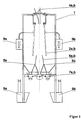
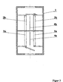
- the housing 1 there are four rows of tube electrodes, the two pairs of electrodes Form 2a, 2b, arranged vertically so that the electrodes are the same Polarity in flight.
- the electrode pairs are not electrical by one conductive wall 3 separated from each other and lie close together. It will two bounded by the wall 3 and the opposite electrodes 2a, 2b Separation spaces formed, each via a separation space inlet 4a, 4b each as Chute is trained to be loaded.
- the position of the shaft 5a, 5b Separation tongues 6a, 6b set separately.
- the separate voltage sources 9a and 9b are expediently in a shielded area of the Electrodes connected.
- the polarity of the electrodes as well as the connection of the product outlets (7a, 7b) with the separating space inlets (4a, 4b) can be varied as desired, the advantages according to the invention occurring and a economic separation success is achieved.
Landscapes
- Electrostatic Separation (AREA)
Description
- Figur 1 -
- Frontansicht
- Figur 2 -
- Seitenansicht
- Figur 3 -
- Querschnitt in Höhe der Elektroden
- Figur 4 -
- Querschnitt durch den Auslaufbereich anhand einer Schaltung mit Vor- und Nachtrennung, Mittelgutrückführung und Ausfuhr von zwei Endprodukten
Claims (6)
- Elektrostatische Trennvorrichtung zur Sortierung triboelektrisch aufgeladener Stoffgemische, bestehend aus in einem Gehäuse (1) senkrecht angeordneten Elektroden gegensätzlicher Polarität, die ein Elektrodenpaar bilden, zwischen denen der Trennraum gebildet wird, einer Einlaufschurre, über die das zu trennende Gemisch im freien Fall in den Trennraum geführt wird sowie Auslaufvorrichtungen zur Ausfuhr der Trennprodukte, dadurch gekennzeichnet, daß an jeder Elektrode jeweils eine separate Spannungsquelle (9a, 9b) derart angeschlossen ist, daß die eine Quelle eine positive Spannung gegen das Potential Erde und die andere eine negative Spannung gegen das Potential Erde liefert und dadurch in Scheidermitte die Potentialdifferenz gegen Erde gleich Null ist.
- Elektrostatische Trennvorrichtung nach Anspruch 1, dadurch gekennzeichnet , daß die Potentialdifferenz gegen Erde unabhängig vom Vorzeichen an beiden Elektroden gleich oder angenähert gleich ist und etwa je 20.000 bis 80.000 Volt beträgt, wodurch sich eine Gesamtpotentialdifferenz zwischen den Elektroden von 40.000 V bis 160.000 V ergibt.
- Elektrostatische Trennvorrichtung nach Anspruch 1, dadurch gekennzeichnet , daß die Elektroden durch zwei dicht nebeneinander angeordnete Elektrodenpaare (2a, 2b) gebildet werden, die durch eine nichtleitende Wand (3) dergestalt voneinander getrennt sind, daß sich die Elektroden gleicher Polarität jeweils in einer Flucht befinden und dadurch zwei Trennräume bilden, die mit je einem Mittelgutauslauf und je einem Auslauf für das positiv bzw. negativ geladene Gut ausgestattet sind, wobei mindestens zwei Produktausläufe vorhanden sind und die übrigen Gutausläufe (7a, 7b) über ein Förderaggregat (8a, 8b) wahlweise mit einem der beiden Trennraumeinläufe (4a, 4b) verbunden sind.
- Elektrostatische Trennvorrichtung nach Anspruch 1 bis 3, dadurch gekennzeichnet , daß die Elektroden als Plattenelektroden, statische Röhrenelektroden, rotierende Röhrenelektroden oder als umlaufende Bänder ausgebildet sind.
- Elektrostatische Trennvorrichtung nach Anspruch 3, dadurch gekennzeichnet, daß das Förderaggregat zwischen den Gutausläufen (7a, 7b) und den Trennraumeinläufen 4a, 4b) z.B. ein Elevator oder ein pneumatisch wirkendes Förderorgan ist.
- Elektrostatische Trennvorrichtung nach Anspruch 1, 3 und 5, dadurch gekennzeichnet, daß sich unmittelbar vor dem Trennraumeinlauf (4a, 4b) eine Aufladevorrichtung befindet.
Applications Claiming Priority (2)
| Application Number | Priority Date | Filing Date | Title |
|---|---|---|---|
| DE19648373 | 1996-11-22 | ||
| DE19648373A DE19648373C1 (de) | 1996-11-22 | 1996-11-22 | Elektrostatische Trennvorrichtung zur Sortierung triboelektrisch aufgeladener Stoffgemische |
Publications (2)
| Publication Number | Publication Date |
|---|---|
| EP0844026A1 EP0844026A1 (de) | 1998-05-27 |
| EP0844026B1 true EP0844026B1 (de) | 2001-09-05 |
Family
ID=7812454
Family Applications (1)
| Application Number | Title | Priority Date | Filing Date |
|---|---|---|---|
| EP97117099A Expired - Lifetime EP0844026B1 (de) | 1996-11-22 | 1997-10-02 | Elektrostatiche Trennvorrichtung zur Sortierung triboelektrisch aufgeladener Stoffgemische |
Country Status (8)
| Country | Link |
|---|---|
| US (1) | US6011229A (de) |
| EP (1) | EP0844026B1 (de) |
| JP (1) | JP3163495B2 (de) |
| KR (1) | KR100226051B1 (de) |
| CN (1) | CN1111454C (de) |
| AT (1) | ATE205116T1 (de) |
| CA (1) | CA2221386C (de) |
| DE (1) | DE19648373C1 (de) |
Families Citing this family (31)
| Publication number | Priority date | Publication date | Assignee | Title |
|---|---|---|---|---|
| US6452126B1 (en) | 1999-03-12 | 2002-09-17 | Mba Polymers, Inc. | Electrostatic separation enhanced by media addition |
| JP2000342997A (ja) * | 1999-06-08 | 2000-12-12 | Hitachi Zosen Corp | プラスチック選別装置 |
| ATE273079T1 (de) * | 2000-01-21 | 2004-08-15 | Univ Western Ontario | Reibungsaufladung und elektrostatisches trennen von gemischten elektrisch isolierten teilchen |
| US6329623B1 (en) * | 2000-06-23 | 2001-12-11 | Outokumpu Oyj | Electrostatic separation apparatus and method using box-shaped electrodes |
| EP1234900A1 (de) * | 2001-02-22 | 2002-08-28 | Jossi Holding AG | Verfahren und Vorrichtung zum Ausscheiden von Fremdstoffen in Fasermaterial, insbesondere in Rohbaumwolle |
| KR100485814B1 (ko) * | 2002-07-11 | 2005-04-28 | 한국지질자원연구원 | 혼합 플라스틱 정전분리장치용 전극판의 배치구조 |
| AU2003281513A1 (en) * | 2002-07-22 | 2004-02-09 | Mba Polymers, Inc. | Mediating electrostatic separations |
| US8436268B1 (en) | 2002-08-12 | 2013-05-07 | Ecullet | Method of and apparatus for type and color sorting of cullet |
| US7351929B2 (en) * | 2002-08-12 | 2008-04-01 | Ecullet | Method of and apparatus for high speed, high quality, contaminant removal and color sorting of glass cullet |
| US7355140B1 (en) | 2002-08-12 | 2008-04-08 | Ecullet | Method of and apparatus for multi-stage sorting of glass cullets |
| US7045734B2 (en) * | 2003-11-21 | 2006-05-16 | Outokumpu Oyj | Spark induction power conditioner for high tension physical separators |
| KR100836003B1 (ko) * | 2007-03-15 | 2008-06-09 | 한국지질자원연구원 | 마찰하전형 정전선별장치 |
| FR2943561B1 (fr) * | 2009-03-27 | 2011-05-20 | Apr2 | Procede de separation electrostatique d'un melange de granules de materiaux differents et dispositif de mise en oeuvre |
| JP5630988B2 (ja) * | 2009-12-07 | 2014-11-26 | 三菱電機株式会社 | 静電選別装置および静電選別方法 |
| JP5110193B2 (ja) * | 2011-07-11 | 2012-12-26 | パナソニック株式会社 | プラスチック粉砕物の静電選別装置 |
| ITRE20110106A1 (it) * | 2011-11-30 | 2013-05-31 | Stefano Cassani | Dispositivo di separazione di particelle di un determinato materiale sintetico da particelle di diversi materiali sintetici, elettricamente caricate |
| WO2014028012A2 (en) * | 2012-08-16 | 2014-02-20 | Empire Technology Development Llc | Electrostatic system and method for sorting plastics |
| AU2013386925B2 (en) * | 2013-04-15 | 2016-05-19 | Posco | Raw material sorting apparatus and method therefor |
| CN103331211A (zh) * | 2013-06-13 | 2013-10-02 | 苏州市丹纺纺织研发有限公司 | 一种静电选棉结构 |
| CN103529312A (zh) * | 2013-10-23 | 2014-01-22 | 中国矿业大学 | 一种微细粒煤粉颗粒荷质比分布测定系统 |
| CN103537379B (zh) * | 2013-10-30 | 2016-03-30 | 上海大学 | 渣金间外加电场的渣金分离装置 |
| CN103736593B (zh) * | 2013-12-06 | 2015-12-09 | 中国矿业大学 | 一种锯齿形微细粒物料摩擦电选机 |
| CN105028200A (zh) * | 2015-07-09 | 2015-11-11 | 武汉轻工大学 | 一种植物人工种子生产装置及方法 |
| KR102019695B1 (ko) * | 2018-02-08 | 2019-09-09 | 성균관대학교산학협력단 | 마찰전기를 이용한 먼지 필터 |
| CN108480054B (zh) * | 2018-02-10 | 2019-12-03 | 中国矿业大学 | 一种壁面摩擦材料旋转可调的粉体电选环保收集装置 |
| JP7047796B2 (ja) * | 2019-02-25 | 2022-04-05 | 三菱電機株式会社 | 樹脂片選別装置及び樹脂片選別方法 |
| FR3099996B1 (fr) * | 2019-08-19 | 2021-11-05 | Skytech | Dispositif de séparation électrostatique, procédé de séparation et utilisation associés |
| CN111617882A (zh) * | 2020-06-11 | 2020-09-04 | 北京协同创新食品科技有限公司 | 一种基于电磁分离的植物粉分离设备及其产品 |
| FR3113613A1 (fr) * | 2020-09-03 | 2022-03-04 | Skytech | Procédé de conception d’un dispositif de séparation électrostatique d’un mélange de granules de matériaux différents et dispositifs associés |
| CN114808198B (zh) * | 2021-01-21 | 2024-06-25 | 香港纺织及成衣研发中心有限公司 | 利用摩擦起电效应分离混合纤维的装置和方法 |
| EP4685469A1 (de) | 2024-07-23 | 2026-01-28 | Mühlenchemie GmbH & Co. KG | Verfahren und vorrichtungen zur vorhersage der verarbeitungseigenschaften von weizenmehl |
Family Cites Families (6)
| Publication number | Priority date | Publication date | Assignee | Title |
|---|---|---|---|---|
| US2782923A (en) * | 1951-03-30 | 1957-02-26 | Internat Mincrals & Chemical C | Method and apparatus for beneficiating ore |
| DE1174274B (de) * | 1962-11-15 | 1964-07-23 | Wintershall Ag | Elektrischer Freifallscheider mit Plattenelektroden |
| DE2609048C2 (de) * | 1976-03-05 | 1983-12-15 | Kali Und Salz Ag, 3500 Kassel | Verfahren und Vorrichtung zur elektrostatischen Aufbereitung von Carnallit enthaltenden Kalirohsalzen |
| US5251762A (en) * | 1992-04-03 | 1993-10-12 | Carpco, Inc. | Electrostatic separation of particles |
| JP3239564B2 (ja) * | 1993-10-20 | 2001-12-17 | 住友電装株式会社 | 静電分別装置 |
| DE4438704C1 (de) * | 1994-10-29 | 1996-04-04 | Kali & Salz Ag | Röhrenfreifallscheider zur Trennung von Kunststoffgemengen |
-
1996
- 1996-11-22 DE DE19648373A patent/DE19648373C1/de not_active Expired - Lifetime
-
1997
- 1997-10-02 EP EP97117099A patent/EP0844026B1/de not_active Expired - Lifetime
- 1997-10-02 AT AT97117099T patent/ATE205116T1/de active
- 1997-10-14 KR KR1019970052490A patent/KR100226051B1/ko not_active Expired - Lifetime
- 1997-11-05 CN CN97120210A patent/CN1111454C/zh not_active Expired - Lifetime
- 1997-11-17 CA CA002221386A patent/CA2221386C/en not_active Expired - Lifetime
- 1997-11-21 JP JP36196997A patent/JP3163495B2/ja not_active Expired - Lifetime
- 1997-11-21 US US08/976,357 patent/US6011229A/en not_active Expired - Lifetime
Also Published As
| Publication number | Publication date |
|---|---|
| ATE205116T1 (de) | 2001-09-15 |
| KR100226051B1 (ko) | 1999-10-15 |
| JP3163495B2 (ja) | 2001-05-08 |
| CA2221386C (en) | 2001-04-03 |
| JPH10156217A (ja) | 1998-06-16 |
| CN1183319A (zh) | 1998-06-03 |
| CA2221386A1 (en) | 1998-05-22 |
| HK1011189A1 (en) | 1999-07-09 |
| CN1111454C (zh) | 2003-06-18 |
| EP0844026A1 (de) | 1998-05-27 |
| DE19648373C1 (de) | 1998-01-08 |
| KR19980041938A (ko) | 1998-08-17 |
| US6011229A (en) | 2000-01-04 |
Similar Documents
| Publication | Publication Date | Title |
|---|---|---|
| DE19648373C1 (de) | Elektrostatische Trennvorrichtung zur Sortierung triboelektrisch aufgeladener Stoffgemische | |
| DE3233528C1 (de) | Elektrostatischer Freifallscheider | |
| EP0154207B1 (de) | Verfahren und Vorrichtung zum Abtrennen elektrisch leitfähiger Nichteisenmetalle | |
| DE20321893U1 (de) | Elektrostatischer Hochspannungsklassifizierer | |
| DE3120945A1 (de) | Elektrostatische sortiervorrichtung | |
| DE3342765A1 (de) | Brechvorrichtung insbesondere fuer harte koernige schuettgueter | |
| EP0427305A1 (de) | Sortierverfahren und -vorrichtung | |
| DE102005023950B4 (de) | Anlage zur Herstellung disperser mineralischer Produkte | |
| WO2008128530A1 (de) | System und verfahren zur staubbindung | |
| DE19931931A1 (de) | Verfahren und Vorrichtung zum Trennen von Partikeln mittels Aufladen durch Reibung | |
| EP0980713B1 (de) | Verfahren und Vorrichtung zur elektrostatischer Trennung eines Bruchgutes | |
| DE3035649A1 (de) | Verfahren zur elektrostatischen trennung von kunststoffgemengen | |
| EP0713728A1 (de) | Röhrenfreifallscheider zur Trennung von Kunststoffgemengen | |
| DE19629110C1 (de) | Verfahren und Vorrichtung zum Trennen von feinteiligen Stoffgemischen mittels eines magnetischen Feldes | |
| DE2049266A1 (de) | Anordnung zum geregelten Austragen von feinkörnigem Gut mit Grobkornanteil | |
| DE102010009846B4 (de) | Verfahren zur elektrostatischen Trennung eine Mineralsalzgemisches | |
| DE1758748C3 (de) | Elektrostatischer Freifall-Scheider | |
| DE1907880C3 (de) | Verfahren und Scheider zum Sortieren feinkörniger Gemenge durch Koronafeld und elektrostatisches Feld | |
| DE19528284C2 (de) | Verfahren und Vorrichtung zum Trennen von Kunststoff-Gemischen | |
| DE2643002C2 (de) | Vorrichtung zur elektrostatischen Aufladung und Trennung von Mineralstoffgemischen | |
| CH622719A5 (de) | ||
| DD279617A1 (de) | Verfahren und vorrichtung zur elektrostatischen aufbereitung | |
| DE2053323A1 (de) | Fliehkraftwindsichter | |
| DE9309075U1 (de) | Magnetscheider | |
| DE1758682A1 (de) | Vorrichtung zur Aufspaltung von Gemischen aus Feststoffpartikelchen in ihre Bestandteile,insbesondere anwendbar fuer feingemahlene Rohsteinkohle,mit Hilfe von elektrostatischer Aufladung in elektrischen Spruehfeldern |
Legal Events
| Date | Code | Title | Description |
|---|---|---|---|
| PUAI | Public reference made under article 153(3) epc to a published international application that has entered the european phase |
Free format text: ORIGINAL CODE: 0009012 |
|
| 17P | Request for examination filed |
Effective date: 19971030 |
|
| AK | Designated contracting states |
Kind code of ref document: A1 Designated state(s): AT BE CH FR GB IT LI NL |
|
| AKX | Designation fees paid |
Free format text: AT BE CH FR GB IT LI NL |
|
| RBV | Designated contracting states (corrected) |
Designated state(s): AT BE CH FR GB IT LI NL |
|
| REG | Reference to a national code |
Ref country code: DE Ref legal event code: 8566 |
|
| 17Q | First examination report despatched |
Effective date: 20000407 |
|
| GRAG | Despatch of communication of intention to grant |
Free format text: ORIGINAL CODE: EPIDOS AGRA |
|
| GRAG | Despatch of communication of intention to grant |
Free format text: ORIGINAL CODE: EPIDOS AGRA |
|
| GRAH | Despatch of communication of intention to grant a patent |
Free format text: ORIGINAL CODE: EPIDOS IGRA |
|
| GRAH | Despatch of communication of intention to grant a patent |
Free format text: ORIGINAL CODE: EPIDOS IGRA |
|
| GRAA | (expected) grant |
Free format text: ORIGINAL CODE: 0009210 |
|
| AK | Designated contracting states |
Kind code of ref document: B1 Designated state(s): AT BE CH FR GB IT LI NL |
|
| REF | Corresponds to: |
Ref document number: 205116 Country of ref document: AT Date of ref document: 20010915 Kind code of ref document: T |
|
| RIN1 | Information on inventor provided before grant (corrected) |
Inventor name: STAHL, INGO, DR. Inventor name: KNAUER, HANS-JUERGEN Inventor name: GEISLER, IRING, DR. |
|
| REG | Reference to a national code |
Ref country code: CH Ref legal event code: EP |
|
| REG | Reference to a national code |
Ref country code: CH Ref legal event code: NV Representative=s name: E. BLUM & CO. PATENTANWAELTE |
|
| GBT | Gb: translation of ep patent filed (gb section 77(6)(a)/1977) |
Effective date: 20011117 |
|
| REG | Reference to a national code |
Ref country code: GB Ref legal event code: IF02 |
|
| ET | Fr: translation filed | ||
| PLBE | No opposition filed within time limit |
Free format text: ORIGINAL CODE: 0009261 |
|
| STAA | Information on the status of an ep patent application or granted ep patent |
Free format text: STATUS: NO OPPOSITION FILED WITHIN TIME LIMIT |
|
| 26N | No opposition filed | ||
| REG | Reference to a national code |
Ref country code: CH Ref legal event code: PFA Owner name: KALI UND SALZ GMBH Free format text: KALI UND SALZ GMBH#POSTFACH 10 20 29#34111 KASSEL (DE) -TRANSFER TO- KALI UND SALZ GMBH#POSTFACH 10 20 29#34111 KASSEL (DE) |
|
| REG | Reference to a national code |
Ref country code: FR Ref legal event code: PLFP Year of fee payment: 20 |
|
| PGFP | Annual fee paid to national office [announced via postgrant information from national office to epo] |
Ref country code: GB Payment date: 20160928 Year of fee payment: 20 |
|
| PGFP | Annual fee paid to national office [announced via postgrant information from national office to epo] |
Ref country code: FR Payment date: 20160919 Year of fee payment: 20 |
|
| PGFP | Annual fee paid to national office [announced via postgrant information from national office to epo] |
Ref country code: BE Payment date: 20160913 Year of fee payment: 20 |
|
| PGFP | Annual fee paid to national office [announced via postgrant information from national office to epo] |
Ref country code: NL Payment date: 20161010 Year of fee payment: 20 Ref country code: CH Payment date: 20161013 Year of fee payment: 20 |
|
| PGFP | Annual fee paid to national office [announced via postgrant information from national office to epo] |
Ref country code: IT Payment date: 20161024 Year of fee payment: 20 Ref country code: AT Payment date: 20160928 Year of fee payment: 20 |
|
| REG | Reference to a national code |
Ref country code: NL Ref legal event code: MK Effective date: 20171001 |
|
| REG | Reference to a national code |
Ref country code: CH Ref legal event code: PL |
|
| REG | Reference to a national code |
Ref country code: GB Ref legal event code: PE20 Expiry date: 20171001 |
|
| REG | Reference to a national code |
Ref country code: AT Ref legal event code: MK07 Ref document number: 205116 Country of ref document: AT Kind code of ref document: T Effective date: 20171002 |
|
| PG25 | Lapsed in a contracting state [announced via postgrant information from national office to epo] |
Ref country code: GB Free format text: LAPSE BECAUSE OF EXPIRATION OF PROTECTION Effective date: 20171001 |
|
| REG | Reference to a national code |
Ref country code: BE Ref legal event code: MK Effective date: 20171002 |