EP0843176A1 - Gefäss - Google Patents
Gefäss Download PDFInfo
- Publication number
- EP0843176A1 EP0843176A1 EP96925960A EP96925960A EP0843176A1 EP 0843176 A1 EP0843176 A1 EP 0843176A1 EP 96925960 A EP96925960 A EP 96925960A EP 96925960 A EP96925960 A EP 96925960A EP 0843176 A1 EP0843176 A1 EP 0843176A1
- Authority
- EP
- European Patent Office
- Prior art keywords
- container
- vessels
- container according
- base member
- vessel
- Prior art date
- Legal status (The legal status is an assumption and is not a legal conclusion. Google has not performed a legal analysis and makes no representation as to the accuracy of the status listed.)
- Granted
Links
Images


Classifications
-
- B—PERFORMING OPERATIONS; TRANSPORTING
- B01—PHYSICAL OR CHEMICAL PROCESSES OR APPARATUS IN GENERAL
- B01L—CHEMICAL OR PHYSICAL LABORATORY APPARATUS FOR GENERAL USE
- B01L3/00—Containers or dishes for laboratory use, e.g. laboratory glassware; Droppers
- B01L3/02—Burettes; Pipettes
- B01L3/0275—Interchangeable or disposable dispensing tips
-
- B—PERFORMING OPERATIONS; TRANSPORTING
- B01—PHYSICAL OR CHEMICAL PROCESSES OR APPARATUS IN GENERAL
- B01L—CHEMICAL OR PHYSICAL LABORATORY APPARATUS FOR GENERAL USE
- B01L3/00—Containers or dishes for laboratory use, e.g. laboratory glassware; Droppers
- B01L3/50—Containers for the purpose of retaining a material to be analysed, e.g. test tubes
- B01L3/508—Containers for the purpose of retaining a material to be analysed, e.g. test tubes rigid containers not provided for above
- B01L3/5085—Containers for the purpose of retaining a material to be analysed, e.g. test tubes rigid containers not provided for above for multiple samples, e.g. microtitration plates
- B01L3/50855—Containers for the purpose of retaining a material to be analysed, e.g. test tubes rigid containers not provided for above for multiple samples, e.g. microtitration plates using modular assemblies of strips or of individual wells
-
- B—PERFORMING OPERATIONS; TRANSPORTING
- B01—PHYSICAL OR CHEMICAL PROCESSES OR APPARATUS IN GENERAL
- B01L—CHEMICAL OR PHYSICAL LABORATORY APPARATUS FOR GENERAL USE
- B01L2200/00—Solutions for specific problems relating to chemical or physical laboratory apparatus
- B01L2200/16—Reagents, handling or storing thereof
-
- G—PHYSICS
- G01—MEASURING; TESTING
- G01N—INVESTIGATING OR ANALYSING MATERIALS BY DETERMINING THEIR CHEMICAL OR PHYSICAL PROPERTIES
- G01N35/00—Automatic analysis not limited to methods or materials provided for in any single one of groups G01N1/00 - G01N33/00; Handling materials therefor
- G01N35/02—Automatic analysis not limited to methods or materials provided for in any single one of groups G01N1/00 - G01N33/00; Handling materials therefor using a plurality of sample containers moved by a conveyor system past one or more treatment or analysis stations
- G01N35/04—Details of the conveyor system
- G01N2035/0401—Sample carriers, cuvettes or reaction vessels
- G01N2035/0429—Sample carriers adapted for special purposes
- G01N2035/0436—Sample carriers adapted for special purposes with pre-packaged reagents, i.e. test-packs
-
- G—PHYSICS
- G01—MEASURING; TESTING
- G01N—INVESTIGATING OR ANALYSING MATERIALS BY DETERMINING THEIR CHEMICAL OR PHYSICAL PROPERTIES
- G01N35/00—Automatic analysis not limited to methods or materials provided for in any single one of groups G01N1/00 - G01N33/00; Handling materials therefor
- G01N35/10—Devices for transferring samples or any liquids to, in, or from, the analysis apparatus, e.g. suction devices, injection devices
- G01N2035/1027—General features of the devices
- G01N2035/1048—General features of the devices using the transfer device for another function
- G01N2035/1053—General features of the devices using the transfer device for another function for separating part of the liquid, e.g. filters, extraction phase
Definitions
- the present invention relates to a container which is suitable for an analysis inspection which requires a high quantitative accuracy. More particularly the present invention relates to the container by which all of the quantity of a specimen in the container can be substantially completely aspirated with being disposed a front end portion of a pipette tip in contact with a surface of the inside bottom of the container. Moreover, the present invention relates to the container which can largely enhance an efficiency of agitating by uniforming a diffusion of the specimen on the occasion of discharging it.
- an inside bottom part of the container is formed so as to have a plane surface or a vertical sectional shape being semicircle or substantially U-like. Therefore, aspirating or discharging a sample and/or a reagent can not be executed in a state that a front end part of a pipette tip remains to be disposed in contact with the inside bottom part of the container.
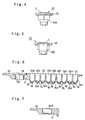
- FIG.16 A conventional means to solve such a problem is shown in Fig.16 for example.
- a front end part 2 of a pipette tip 1 is cut diagonally in order to be able to aspirate and discharge a sample S in a state that the front end part 2 of the pipette tip 1 is disposed in contact with an inside bottom part 4 of a container 3.
- another conventional means in which has one or more caves 5 are mounted in the front end part of the pipette tip 1 is proposed. It is designed so that an opening of the pipette tip 1 can not be blockaded by the contact with the inside bottom part 4 of the container 3.
- the conventional means which is bored by caves 5 in the front end part of the pipette tip 1, cannot aspirate a liquid S below the position where the caves 5 are bored, too. Also, when the aspirated liquid is discharged, the liquid is discharged only in the direction of the opening of the caves 5. Therefore, the conventional means has the problem that it is difficult to get a uniform agitating effect. Moreover, as the manufacturing step to bore one or more caves 5 is necessary, the conventional means has a problem that the manufacture of pipette tip 1 is complicated and a manufacture cost increases.
- the conventional means When liquid is aspirated and discharged in a state that the front end part of the pipette tip is kept to be lifted from the surface of the bottom part of the container, samples or reagents are tend to stick to the outside surface of the pipette tip. Therefore, the conventional means has a problem that a concentration of a sample is changed by samples or reagents being stuck and has a problem that the conventional means is difficult to get high precision results.
- the present invention has been accomplished under these circumstances and has the following objects.
- the container according to the first aspect of the present invention comprises a gap part formed at an inside bottom part of the container to have a smaller width than a caliber of a front end portion of a liquid sucking/discharging line adapted to be inserted in the container and pulled out of the container, wherein the gap part is formed to have a shape being capable of aspirating and discharging all of the quantity of liquid through the front end portion even in a state that the front end portion is disposed in contact with the inside bottom part.
- the reliable dispensing and/or agitating step by a pipette device can be realized by constituting so as to be able to aspirate and/or discharge a predetermined amount without blockading the front end portion of the liquid sucking/discharging line when the samples and/or reagents in container are aspirated and/or discharged.
- the present invention can aspirate all of the quantity in the container, a surplus of samples or reagents are not necessary to compensate the remaining amount.
- the present invention can treat all of the quantity as being a fixed, the present invention can realize a high precision inspection of all of the quantity.
- the container can be inexpensively provided because of the simple structure.
- a second aspect of the present invention is that, in the first aspect, the gap part comprises a ditch or ditches having a longer size than the caliber of the front end portion of the liquid sucking/discharging line, and being formed to be substantially concave in a vertical section.
- the depth of the ditch or ditches is not restricted to a particular size, it is preferable that the depth is determined to be so shallow as to achieve aspirating all of the quantity.
- the present aspect of the invention can be more effective than the first aspect of the invention in regard to the uniforomity of agitating.
- a third aspect of the present invention is that, in the second aspect, the plural ditches are arranged so as to be radiated.
- the radiated arrangement includes asterisk, cross and three-forked road arrangement et al..
- a forth aspect of the present invention is that, in the first aspect, the gap part is formed so as to have plural concavities or convexities having a smaller size than the caliber of the front end portion of the liquid suckling/discharging line.
- a fifth aspect of the present invention is that, in the first to fourth aspect, the gap part is formed so as to have a falling slope extending towards the center of the inside bottom part of a main body of the container.
- a sixth aspect of the present invention is that, in the first to fifth aspect, plural vessels for storaging liquid and so on are arranged along a line or lines so as to form a cartridge container or a microplate.
- This aspect of the invention can realize narrowing a necessary space by accumulating the vessels in a high density and can realize the efficient treatment by shortening a transferring distance of the contents in vessels, by a quick and prompt operation, and by saving energy. Furthermore, a container can be provided in a low price with being a simple structure by accumulating vessels in a high density. As the vessel for measuring light and so on are accumulated in a cartridge container or a microplate, the process from beginning to end can be executed by only one container, and the process can efficiently and promptly be executed by reducing the necessity of the mechanical driving movement.
- a seventh aspect of the present invention is that, in the sixth aspect, each vessel is formed to be elliptic in a horizontal section.
- the container of this aspect of the invention is formed to be substantially elliptic, the flow of liquid becomes irregular when pipette tip discharges liquid, and the agitating efficiency can be improved by this aspect of the invention.
- a container may be comprised of a single vessel formed so as to be substantially concave in a vertical section.
- a container may be comprised of a cartridge container or a microplate, in the main body of which plural vessels are arranged in a straight line or lines. It is preferable that a horizontal section of each vessel for storaging liquid is formed so as to be elliptic.
- An eighth aspect of the present invention is that, in the sixth or seventh aspect, vessels have various shapes or various capacities determined by a content of process.
- the container can be constituted so as to be able to execute necessary treatment by only one container, the process can be completed efficiently and quickly.
- a ninth aspect of the present invention is that, in the first to eighth aspect, the container is used for the process of liquid containing magnetic particles.
- process for the liquid containing magnetic particles is chemical luminousness inspection methods or EIA inspection methods such as the CLIA inspection method or the CLEIA inspection method and so on.
- EIA inspection methods such as the CLIA inspection method or the CLEIA inspection method and so on.
- the other inspection method an extraction method, and a measurement method, too.
- a tenth aspect of the present invention is that, in the first to ninth aspect, in each vessel, an antigen, an antibody, an enzyme or a DNA probe and so on is contained in the solid phase.
- an antigen, an antibody, an enzyme or a DNA probe and so on is contained in the solid phase.
- is contained in the solid phase means that an antigen and so on sticks to the inside wall of the container and so on in solid phase by coating and so on.
- the cartridge container has a base member, and plural vessels arranged along a line or lines in the base member, wherein the plural vessels comprise the necessary number of vessels for treatment, vessels for measuring light being able to couple with an optical measuring apparatus or an optical receiving unit in a light shielded state, or hole parts holding it, vessels accommodating or hole parts holding a pipette tip, tubes for PCR or hole parts holding it, or, vessels being contained in the solid phase or hole parts holding it, according to the process.
- the process from beginning to the optical measurement can be completed by only one container. Therefore, the necessity of the mechanical driving movement can be suppressed to the minimum. Also, the process can be promptly reliably and collectively executed by reducing the distance and the time for the transfer of liquid and so on.
- a twelfth aspect of the present invention is that, in the sixth to tenth aspect, the microplate has a base member, and plural vessels arranged in a matrix in the base member, wherein the plural vessels belonging to a group of vessels formed by dividing the matrix row-wise or column-wise comprises the necessary number of vessels for treatment, vessels for measuring light being able to couple with an optical measuring apparatus or an optical receiving unit in a light shielded state, or hole parts holding it, vessels accommodating or hole parts holding a pipette tip, tubes for PCR or hole parts holding it, or, vessels being contained in the solid phase or hole parts holding it, according to the process.
- a tube for PCR (polymerase chain reaction) is the tube whose shape is adapted to the equipment for the amplification of DNA.
- the vessel for measuring light comprises a measuring vessel shielded from external light and a hole part holding it dismountably, in the case the base member of the cartridge container or microplate is made of such a transmission material as a transparent material or a translucent material.
- the measuring vessel has a light shielding characteristic can be made as a separate members from the microplate made of a material having a light transmitting characteristic. Consequently, manufacture of them as separate members can be more easier than that as one integral member, and the cost can be reduced.
- a fourteenth aspect of the present invention is that, in the eleventh or twelfth aspect, the vessel for measuring light and the base member are formed as a unitary body in the case that the base member of the cartridge container or microplate is made of a light shielding material.
- a fifteenth aspect of the present invention is that, in the eleventh to thirteenth aspect, the measuring vessel held in the vessel for measuring light has a coupling means to couple with an optical measuring apparatus or an optical receiving unit in a light shielded state, at the upper end of the meaning vessel, wherein the inside wall of the measuring vessel is formed so as to be of a high reflective rate by applying with white color and so on, and the outside of the measuring vessel is covered by a light shielding material.
- white color be made of white material, be applied with metallic color, or be made of a metal and so on.
- a sixteenth aspect of the present invention is that, in the sixth to fifteenth aspect, the microplate or the cartridge container comprises a base member being formed so as to be substantially plate-like, plural vessels being arranged in a matrix or in a line in the base member, a wall-like leg part being projecting downwards at an edge of the base member so as to be lower than the outside bottom of the vessel in order to support the base member.
- a seventeenth aspect of the present invention is that, in the sixth to sixteenth aspect, the microplate or the cartridge container comprises a base member being formed so as to be substantially plate-like, plural vessels arranged in a matrix or in a line in the base member, and a partition or partitions with a fixed height being arranged along parallel to an edge of the base member or a boundary or boundaries separating between groups of vessels.
- An eighteenth aspect of the present invention is that, in the sixth to seventeenth aspect, one of the vessels is formed so that the structure is adapted to a thermostatic means.
- a thermostatic means for example, a thermostatic tank
- the tank should be formed so that the vessels can be contained in it.
- this invention can more efficiently and more completely fascinate the temperature of liquid to be kept at a predetermined temperature by transferring liquid from a liquid storage vessel to a vessel maintained at a predetermined temperature.
- the reaction can more efficiently be executed by this aspect of the invention, and the amplification can be executed more easily and in a shorter time.
- the mechanism for transferring the container needs not be mounted, the structure of the equipment can be simplified. Furthermore, all the process including the control of temperature, can be executed with one continuous operation by this aspect of the invention.
- a nineteenth aspect of the present invention is that, in the eighteenth aspect, a lid body having a slit being able to be inserted by the pipette tip, is mounted so as to have a structure being adapted to a thermostatic means.
- a twentieth aspect of the present invention is that, in the sixth to ninteenth aspect, a seal being able to be penetrated by the pipette tip, is attached by a heat deposition or a supersonic deposition to the upper surface of the base member of the cartridge container or the microplate in order to cover the opening of the each vessel.
- a seal being able to be penetrated by a pipette tip may be not only the tender thin film being easily penetrated, but also the tough one having a hole.
- the seal may be not only transparent, but also translucent or opaque, and may be made of aluminium foil or polyvinyl-chloride and so on.
- the front end portion of the pipette tip needs penetrate the seal and be inserted into the container.
- a twenty-first aspect of the present invention is that, in the sixth to twentieth aspect, the microplate comprises plural cartridge containers in which the vessels are arranged in a row-wise or column-wise line and a binding part formed so as to be substantially like teeth of a comb having intervals between the cartridge containers being able to be inserted in by the partition and binding the end of each cartridge container, wherein the partitions are arranged so as to be substantially in parallel mutually at a fixed interval on the stage putting the microplate in order to partition the cartridge containers mutually.
- the size of a fixed interval needs be large enough for the cartridge containers of the microplate or each nozzle of multi-nozzle for dispensing to be capable of being separated between partitions one by one, with a certain space.
- the height of the partition is great enough to prevent from mixing a splash of liquid etc. arisen from pouring etc..
- air curtains may be mounted between cartridge containers in order to prevent from mixing a splash of liquid etc.. As each neighboring cartridge container can be separated by a partition, mixture of substances other than target substances between the different cartridge containers (cross-contamination) can be efficiently avoided, and reliable treatment can be executed.
- a twenty-second aspect of the present invention is that, in the twenty-first aspect, the binding part is formed so as to have such a strength as each cartridge container to be cut easily.
- the binding part can be cut every cartridge container easily, only the necessary number of the cartridge containers can be cut off from the binding part and be used according to the content of the process, and therefore, cartridge container can be efficiently used without waste and efficiently.
- the cartridge containers and the binding part are formed in a unitary body, the manufacture of the container can be simplified and the cost can be reduced. For example, to be cut easily can be attained by forming the binding part to be thin.
- a twenty-third aspect of the present invention is that, in the sixth to twenty-second aspect, the necessary number of the vessels of the cartridge container according to the process are arranged along a locus of a moving nozzle of the liquid sucking/discharging line, and the necessary number of the vessels of microplate according to each process are arranged in parallel along loci of moving nozzles of the liquid sucking/discharging lines.
- FIGs. 1 to 6 show a container of the first embodiment of the present invention.
- a container 10 of this embodiment comprises a cartridge container which has a main body 11 of the container made of glass or plastic and so on in a unitary body and a knob 12 formed in the one end of this main body 11.
- the above liquid storage vessels 13A to 13I are made of a transparent plastic or glass so as to be capable of seeing through the substances contained in the vessels from outside. Therefore, the inside wall and bottom of the measuring vessel 14 made of a transparent body, which can be dismountably held in the hole 13J holding a vessel, is coated by a light shielding film so as to be capable of measuring a weak chemi-luminescence surely.
- the container 10 of this embodiment comprises two parts, one of which is the main body 11 made of a transparent body, and the other of which is the measuring vessel 14.
- the measuring vessel 14 there are other means which are constituted so as to be able to measure a weak chemi-luminescence surly.
- One means comprises three parts being assembled to a unitary body, which is constituted so that a light shielding film and a light shielding board is covered in the inside wall and the bottom part.
- another means is constituted so that a main body 11 itself may be made of an opaque material having a excellent light shielding characteristic or may be formed so as to be a unitary body being applied with such a color with an excellent light shielding characteristic as black or white etc..
- the above measuring vessel 14 is used with being a transparent body
- the above hole 13J holding the measuring vessel 14 is formed so as to have a bottom.
- the hole 13J may be formed as a unitary body by coating the inside surface of it, may be assembled to a unitary body by covering a light shielding board, or may be formed by applying with such a color with an excellent light shielding characteristic as black or white color etc..
- the measuring vessel 14 may be constituted as a measuring hole part 14A which is formed as a unitary body together with a line of liquid storage vessels in the main body 11.
- a shielding film is coated on the inside wall and bottom of the measuring hole part 14A.
- the measuring hole part is assembled to a unitary body with covering a shielding board on the inside wall and bottom of the hole part or making a shielding layer 14B by applying with such a color with an excellent light shielding characteristic as black color or white color and so on.
- the light other than the one arisen from reaction can be shielded, by forming the measuring vessel 14 or the measuring hole part 14A, for example, in the case that the measuring vessel 14 is used for measuring the chemi-luminescence.
- the measuring vessel is used with being a transparent body.
- the arrangement of the above measuring vessel 14 or the measuring hole part 14A is not limited to the case of this embodiment shown in figures. It is needless to say that the measuring vessel 14 or the measuring hole part 14A can be arranged at suitable positions according to the number of processing steps of measuring items.
- the above nine liquid storage vessels 13A to 13I are formed so as to be substantially elliptic in a horizontal section, and are formed so as to be substantially V-shape (the illustrated example is the case that the cross angle is 90° ) in a vertical section of them.
- a ditch 16 whose vertical sectional shape is substantially concave, is mounted along an inclined surface of each inside bottom part 15a.
- the size d of the width of this ditch 16 is formed to be smaller than the size "D" of the caliber of a front end portion 22 of the pipette tip 21 (D>d). Also, the length of the ditch 16 is formed to be longer than the caliber of the front end portion 22. Therefore, as is shown in Fig.8, even if the front end portion 22 of the pipette tip 21 is disposed in contact with a surface of the inside bottom part 15a, all of the quantity of samples and/or reagents contained in vessels 13A to 13I can be aspirated by flow along the ditch 16. Also, a high quantitative accuracy necessary to this kind of equipment can be surely guaranteed by this embodiment. And the waste of the amount of samples and/or reagents can be avoided.
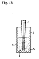
- samples and/or reagents 18 containing magnetic particles 17 which are used in such an analysis inspection of the chemi-luminescence as a measuring method of CLIA or CLEIA etc. is shown in Fig. 18.
- the samples and/or reagents used in this invention does not limit to the case of this embodiment.
- this embodiment can be applied to an inspection of EIA which is achieved by providing a vessels to whose inside wall is stuck to, for example by antigen and antibody in the solid phase. It is needless to say that this embodiment is not limited to the stated method given as an example, but can be applied to the other method.
- the number of the liquid storage vessels 13A to 13I is not limited to this shown embodiment. It is needless to say that the number of the vessels can be varied according to the number of the reaction steps of the measuring items.
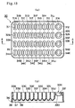
- Fig. 10 shows a plane view of the liquid storage vessels 13 of the container 10 of the second embodiment of this invention.
- ditches 16 A each of the structure is formed to be similar to the ditch 16 of the first embodiment, are arranged so as to be radiated.
- all of the quantity of the samples and/or reagents in the liquid storage vessels 13 can be aspirated and/or discharged more promptly and more surely.
- Fig. 11 shows a plane view of liquid storage vessels 13 of a container 10 of the third embodiment.
- ditch 16 or ditches 16A of the first embodiment or the second embodiment plural concavities or convexities 16b are mounted.
- this size of the distance between concavities or convexities is formed to be smaller than that of the caliber of the front end portion of the pipette tip 21, and is formed to be slightly larger than the diameter of the opening of the front end portion in order to discharge and/or aspirate all of the quantity of samples and/or reagents.
- microplate 30 in which the liquid storage vessels are arranged in a matrix, is described as the fourth embodiment of the present invention.
- Microplate 30 is used for process which is executed by plural liquid sucking/discharging lines stood in parallel. Each line of vessels in the microplate is used, when work of separating, taking out, pipetting, cleaning, condensing, and/or diluting said target high molecular substance and so on or/and works for capturing, extracting, isolating, amplifying, labeling, and/or measuring the substance and so on are executed according to the same timing.
- microplate 30 of this embodiment comprises substantially plate-like base member 35 made of a transparent or translucent material, and plural vessels 31A-31K, 32A-32K, 33A-33K, 34A-34K arranged in a matrix-shape in the base member 35.
- Plural vessels comprise the four groups of vessels 31A-31K, 32A-32K, 33A-33K, 34A-34K which are formed by dividing the matrix into each column (or row).
- the vessels 31K, 32K, 33K, 34K at the end of each group of the vessels formed by dividing into each column (row) are those for measuring light which can be coupled with an optical measuring apparatus or an optical receiving unit (is not shown in a figure) in a light shielded state.
- the vessels 31K,32K,33K,34K comprises hole parts 330 which dismountably hold the measuring vessel 331 which is shielded from an external light and can measure an internal light.
- the reason for this separate members structure is as follows: The base member 35 itself has not a light shielding characteristic and the measuring vessel 331 needs have a light shielding characteristic. Therefore, the manufacture as separate members is more easier than that as one integral member.
- the measuring vessel 331 has the structure that the outer part is made of the black materials having a light shielding characteristic and the inner part is made of the white materials having a light shielding characteristic and an excellent reflection characteristic.
- the coupling portion 332 is mounted which has an annular projection coupling with the optical measuring apparatus or the optical receiving unit in a light shielded state.
- the annular projection presses against an elastic packing mounted in the optical measuring apparatus or optical receiving unit, and the light is completely shielded.
- the measuring vessel 331 being as separate member from the base member, can be manufactured inexpensively and more easily than the case that the black measuring vessel 331 made of the materials having a light shielding characteristic is mounted in the base member 35 as one integral member.
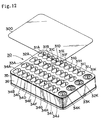
- Fig. 12 shows that the seal 300 which is made of a transparent and thin film which can easily be inserted by the front end portion of the pipette tip, is preferably mounted on the upper surface of the microplate 30 by heat disposition or super-sonic disposition in order to cover each vessel.
- the seal 300 which is made of a transparent and thin film which can easily be inserted by the front end portion of the pipette tip, is preferably mounted on the upper surface of the microplate 30 by heat disposition or super-sonic disposition in order to cover each vessel.
- Fig.13 shows that the microplate 30 is provided with a wall-like leg part 36 in order to support the base member 35 which is projected downward at the edge of the base member 35 so as to be lower than the outside bottom part 39. Also, ribs 38 for reinforcement are mounted between the neighboring vessels. Consequently, microplate can stably be placed on the stage of the pipette device.
- Fig. 14 shows the fifth embodiment of the present invention.
- the microplate 40 of this embodiment has eight lines of the group of the vessels 41A-41H, ⁇ 48A-48H. At the end of each group of the vessels, the tip holding vessels 41A-48A are mounted in order to hold the pipette tips 51 being dismounted. At the other end of each group of vessels, measuring vessels 41H-48H are mounted.
- the vessels 41B-41G, ⁇ ,48B-48G mounted at the positions except the both ends are formed so as to have various capacities corresponding to the necessary amount of liquid (reagent etc.) according to the treatment.
- Fig. 14(a) On the left end of Fig. 14(a), it is shown that eight pipette tips 51 which are equipped with eight nozzles of pipette device executing distribution to the vessels for reaction, eight permanent magnets 52, and transferring body 50 which holds and transfers the eight permanent magnets 52.
- the permanent magnet 52 is used in order to control a reaction, agitation, separation, cleaning and movement etc. of magnetic particles 53 at the same time, by being simultaneously brought close to or away from a liquid passage which has a middle diameter and joins a reservoir portion having a larger diameter with the front end portion, or by applying a magnetic field to or removing it from the liquid passage.
- the permanent magnets, 8 in number for example, are disposed in parallel with each other, and in such a manner that the S and N poles alternately occurred. By this structure, the interference of the magnetic field between the neighboring permanent magnets can be avoided, and the stable control can be executed.
- such a structure as a ditch which is substantially concave in a vertical section, is mounted along the inclined surface is the similar to the one that has already been explained by Fig. 1 and so on.
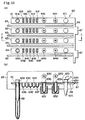
- the sixth embodiment is a container being suitable to the process of the inspection of DNA.
- the microplate 60 of this embodiment comprises plural cartridge containers 61,62,63,64 in which vessels are arranged in a line of each column or each row, and the binding part 66 which is formed to be substantially like teeth of a comb, and which binds each end part of cartridge containers arranged at a fixed interval between neighboring cartridge containers.
- the knob 67 is mounted in the binding part 66 for grasping the microplate 60.
- the cartridge container and binding part and so on are formed in a unitary body by a metal molding.
- a fixed interval is determined to be slightly wider than the thickness of the partition 65 arranged on the stage where the microplate 60 is placed in order that the partition 65 can be inserted.
- tip holding vessel 63A which holds the pipette tip 69 being dismounted from nozzle, is mounted.
- hole part 63I which holds the tubes 635 for PCR that is used for measuring the DNA, is mounted.
- a lid body 633 can be opened or closed freely, is mounted at the upper end of the tube 635 for PCR.
- the lid body 633 and the body of the tube are formed so as to be in a unitary body.
- the tube 635 is supported by the hole part 63I at the flange 634 mounted in the tube 635.
- treating vessels 63B, 63C, 63D, 63E, 63F, 63G, 63H for treating liquid are included.
- vessels 63G, 63H are mounted so as to be placed at such a position and have such a size, as being able to be contained in a thermostatic tank 631, 632 corresponding to the thermostatic means, and are kept at a predetermined temperature 60° C, 90° C and so on by this thermostatic tank.
- the vessels are placed away from the other vessels to some extent in order to give no affection by conduction of the heat.
- the vessels 63G, 63H are covered by the lid body 630 which is made of elastic body and has a cross-like slit.
- the lid body 630 which is made of elastic body and has a cross-like slit.
- the container 60 is put on the stage from above the partitions 65, so that the partitions 65 are stuck out of the intervals of the teeth-of-a-comb-like container 60.
- the partitions 65 stands at a fixed interval in parallel, and each cartridge container 61-64 of the microplate 60 is placed in each interval between the partitions 65.
- the vessels 63G, 63H etc. are placed at a predetermined position within a thermostatic tank 631,632. Then, four pipette tips equipped to the four nozzles moves along parallel to the partitions 65, and execute aspirating/discharging and so on at the same time.
- reference numeral 70 represents a filter.
- a ditch whose vertical section is substantially concave is mounted along the inclined surface.
- each cartridge container is separated by the partition 65. Therefore, cross-contamination by mixing substances except the target substance like DNA etc. can be avoided between processing lines of cartridge containers 61-64.
- the rectangular plate body is disclosed as a partition, an air absorbing device which has an absorbing air opening elongated along lines may be mounted between processing lines, instead of the partition. By this embodiment, a curtain of downward air stream is generated. Consequently the interchange of the air etc. between the neighboring lines, and can prevent from mixing liquid etc. from the other lines can be avoided.
- the above containers 10 are not only limited to the case that the liquid storage vessels 13A-13I are arranged to be line-like, or are formed to be microplate-like, but also may be arranged to be loop-like or zigzag-like. Or, the container may be formed so as to have a single vessel which is formed to be similar to the above liquid storage vessel. Also, in the above embodiments, the number and the sort of the vessels being mounted in the microplate and the cartridge container are not limited to the above examples. It is needless to say that the number and the sort can be varied as occasion demands.
Priority Applications (2)
| Application Number | Priority Date | Filing Date | Title |
|---|---|---|---|
| EP10176863A EP2275821A1 (de) | 1995-07-31 | 1996-07-31 | Behälter |
| EP10176871A EP2259070A3 (de) | 1995-07-31 | 1996-07-31 | Gefäss |
Applications Claiming Priority (3)
| Application Number | Priority Date | Filing Date | Title |
|---|---|---|---|
| JP213051/95 | 1995-07-31 | ||
| JP21305195 | 1995-07-31 | ||
| PCT/JP1996/002158 WO1997005492A1 (fr) | 1995-07-31 | 1996-07-31 | Recipient |
Related Child Applications (2)
| Application Number | Title | Priority Date | Filing Date |
|---|---|---|---|
| EP10176871.1 Division-Into | 2010-09-15 | ||
| EP10176863.8 Division-Into | 2010-09-15 |
Publications (3)
| Publication Number | Publication Date |
|---|---|
| EP0843176A1 true EP0843176A1 (de) | 1998-05-20 |
| EP0843176A4 EP0843176A4 (de) | 2000-04-12 |
| EP0843176B1 EP0843176B1 (de) | 2013-06-12 |
Family
ID=16632721
Family Applications (3)
| Application Number | Title | Priority Date | Filing Date |
|---|---|---|---|
| EP96925960.5A Expired - Lifetime EP0843176B1 (de) | 1995-07-31 | 1996-07-31 | Analysesystem umfassend einen Behälter und eine Vorrichtung zum Aufsaugen und Abgeben einer Flüssigkeit |
| EP10176871A Withdrawn EP2259070A3 (de) | 1995-07-31 | 1996-07-31 | Gefäss |
| EP10176863A Withdrawn EP2275821A1 (de) | 1995-07-31 | 1996-07-31 | Behälter |
Family Applications After (2)
| Application Number | Title | Priority Date | Filing Date |
|---|---|---|---|
| EP10176871A Withdrawn EP2259070A3 (de) | 1995-07-31 | 1996-07-31 | Gefäss |
| EP10176863A Withdrawn EP2275821A1 (de) | 1995-07-31 | 1996-07-31 | Behälter |
Country Status (6)
| Country | Link |
|---|---|
| US (3) | US6143250A (de) |
| EP (3) | EP0843176B1 (de) |
| JP (1) | JP3985872B2 (de) |
| AU (1) | AU722335B2 (de) |
| CA (1) | CA2226776C (de) |
| WO (1) | WO1997005492A1 (de) |
Cited By (20)
| Publication number | Priority date | Publication date | Assignee | Title |
|---|---|---|---|---|
| US6063341A (en) * | 1997-06-09 | 2000-05-16 | Roche Diagnostics Corporation | Disposable process device |
| WO2000029110A1 (en) * | 1998-11-18 | 2000-05-25 | Pepscan Systems B.V. | Matrix plate, method and apparatus for sample analysis |
| WO2000058736A1 (en) * | 1999-03-25 | 2000-10-05 | Coulter International Corp. | Apparatus for aspirating liquid from a vessel |
| EP1110609A2 (de) * | 1999-12-24 | 2001-06-27 | Roche Diagnostics GmbH | System zur Bearbeitung von Proben in einer Mehrkammeranordnung |
| WO2001052988A1 (de) * | 2000-01-21 | 2001-07-26 | Greiner Labortechnik Gmbh | Behälter zur lagerung von biologischem material |
| WO2001068258A1 (en) * | 2000-03-15 | 2001-09-20 | American Cyanamid Company | Pipette tip |
| EP1154274A2 (de) * | 2000-05-08 | 2001-11-14 | ARKRAY, Inc. | Verfahren zur Untersuchung einer Probe mit einem Reagenz |
| EP1255115A2 (de) * | 2001-05-02 | 2002-11-06 | DIESSE DIAGNOSTICA SENESE S.p.A. | Immunoenzymatische Testvorrichtung für einmalige Verwendung sowie Verwendungsverfahren |
| WO2006050953A1 (de) * | 2004-11-11 | 2006-05-18 | Orgentec Diagnostika Gmbh | Vorrichtung zur vollautomatischen durchführung eines einzelimmunoassays |
| US8546110B2 (en) | 1998-05-01 | 2013-10-01 | Gen-Probe Incorporated | Method for detecting the presence of a nucleic acid in a sample |
| US8840848B2 (en) | 2010-07-23 | 2014-09-23 | Beckman Coulter, Inc. | System and method including analytical units |
| US8973736B2 (en) | 2011-11-07 | 2015-03-10 | Beckman Coulter, Inc. | Magnetic damping for specimen transport system |
| US9046506B2 (en) | 2011-11-07 | 2015-06-02 | Beckman Coulter, Inc. | Specimen container detection |
| US9446418B2 (en) | 2011-11-07 | 2016-09-20 | Beckman Coulter, Inc. | Robotic arm |
| US9482684B2 (en) | 2011-11-07 | 2016-11-01 | Beckman Coulter, Inc. | Centrifuge system and workflow |
| US9506943B2 (en) | 2011-11-07 | 2016-11-29 | Beckman Coulter, Inc. | Aliquotter system and workflow |
| US9910054B2 (en) | 2011-11-07 | 2018-03-06 | Beckman Coulter, Inc. | System and method for processing samples |
| WO2020127897A1 (en) * | 2018-12-20 | 2020-06-25 | Tecan Trading Ag | Tip cup |
| WO2022200561A1 (de) | 2021-03-25 | 2022-09-29 | Heinrich-Heine-Universität Düsseldorf | Vorrichtung zum effizienten mediumwechsel in mikrotiterplatten |
| EP4101537A3 (de) * | 2007-07-13 | 2023-03-22 | Handylab, Inc. | Integrierte vorrichtung zur durchführung von nukleinsäureextraktionen und diagnosetests mehrerer biologischer proben |
Families Citing this family (144)
| Publication number | Priority date | Publication date | Assignee | Title |
|---|---|---|---|---|
| EP0843176B1 (de) * | 1995-07-31 | 2013-06-12 | Precision System Science Co., Ltd. | Analysesystem umfassend einen Behälter und eine Vorrichtung zum Aufsaugen und Abgeben einer Flüssigkeit |
| US6048734A (en) | 1995-09-15 | 2000-04-11 | The Regents Of The University Of Michigan | Thermal microvalves in a fluid flow method |
| ATE282473T1 (de) * | 1997-05-02 | 2004-12-15 | Gen Probe Inc | Reaktion behälter apparat |
| US6063338A (en) * | 1997-06-02 | 2000-05-16 | Aurora Biosciences Corporation | Low background multi-well plates and platforms for spectroscopic measurements |
| US5910287A (en) * | 1997-06-03 | 1999-06-08 | Aurora Biosciences Corporation | Low background multi-well plates with greater than 864 wells for fluorescence measurements of biological and biochemical samples |
| US6171780B1 (en) | 1997-06-02 | 2001-01-09 | Aurora Biosciences Corporation | Low fluorescence assay platforms and related methods for drug discovery |
| JPH11183484A (ja) * | 1997-12-17 | 1999-07-09 | Olympus Optical Co Ltd | 自動分析装置 |
| US6387331B1 (en) * | 1998-01-12 | 2002-05-14 | Massachusetts Institute Of Technology | Method and apparatus for performing microassays |
| US6861035B2 (en) | 1998-02-24 | 2005-03-01 | Aurora Discovery, Inc. | Multi-well platforms, caddies, lids and combinations thereof |
| GB9922971D0 (en) * | 1999-09-29 | 1999-12-01 | Secr Defence | Reaction system |
| EP1760466B1 (de) | 2000-04-28 | 2014-06-04 | Mitsubishi Chemical Medience Corporation | Messverfahren und Instrument unter Einsatz einer Messkassette |
| US6734401B2 (en) * | 2000-06-28 | 2004-05-11 | 3M Innovative Properties Company | Enhanced sample processing devices, systems and methods |
| FR2812088B1 (fr) * | 2000-07-21 | 2003-01-24 | Abx Sa | Dispositif de traitement d'echantillons de produits sanguins |
| US6537502B1 (en) * | 2000-07-25 | 2003-03-25 | Harvard Apparatus, Inc. | Surface coated housing for sample preparation |
| US6692700B2 (en) | 2001-02-14 | 2004-02-17 | Handylab, Inc. | Heat-reduction methods and systems related to microfluidic devices |
| ES2337850T3 (es) | 2001-03-09 | 2010-04-29 | Gen-Probe Incorporated | Caperuza perforable. |
| US8895311B1 (en) | 2001-03-28 | 2014-11-25 | Handylab, Inc. | Methods and systems for control of general purpose microfluidic devices |
| US7010391B2 (en) | 2001-03-28 | 2006-03-07 | Handylab, Inc. | Methods and systems for control of microfluidic devices |
| US7829025B2 (en) * | 2001-03-28 | 2010-11-09 | Venture Lending & Leasing Iv, Inc. | Systems and methods for thermal actuation of microfluidic devices |
| US6852287B2 (en) | 2001-09-12 | 2005-02-08 | Handylab, Inc. | Microfluidic devices having a reduced number of input and output connections |
| US7323140B2 (en) | 2001-03-28 | 2008-01-29 | Handylab, Inc. | Moving microdroplets in a microfluidic device |
| EP1251345A1 (de) * | 2001-04-12 | 2002-10-23 | Fuji Photo Film Co., Ltd. | Messsensor mit dem Prinzip der abgeschwächten Totalreflexion und Messchipanordnung |
| GB0110476D0 (en) * | 2001-04-30 | 2001-06-20 | Secr Defence | Reagent delivery system |
| EP1390760B1 (de) | 2001-05-09 | 2008-06-18 | Axis-Shield Asa | Testvorrichtung |
| US6800491B2 (en) | 2001-06-08 | 2004-10-05 | Nalge Nunc International Corporation | Robotic reservoir without liquid hangup |
| US20030007897A1 (en) * | 2001-07-06 | 2003-01-09 | Andrew Creasey | Pipette tips |
| US6656267B2 (en) | 2001-07-10 | 2003-12-02 | Structural Genomix, Inc. | Tray for macromolecule crystallization and method of using the same |
| US6827905B2 (en) * | 2002-01-14 | 2004-12-07 | Becton, Dickinson And Company | Pin tool apparatus and method |
| CA2481545A1 (en) * | 2002-04-12 | 2003-10-23 | Instrumentation Laboratory Company | Immunoassay probe |
| IL155897A0 (en) * | 2003-05-13 | 2003-12-23 | Amon Valinsky | An indicator for multiwell plate and method for using the same |
| SE527896C2 (sv) * | 2003-05-20 | 2006-07-04 | Aamic Ab | Optisk testanordning för biologiska prover, samt en microarray till anordningen och metoden för dess användning |
| EP1650570B1 (de) | 2003-07-17 | 2021-05-26 | LSI Medience Corporation | Gerät zur verwendung zur messung einer komponente, die in einer probe enthalten ist, die ein messgerät und eine kartusche enthält |
| US20050013743A1 (en) * | 2003-07-18 | 2005-01-20 | Edward Francis Farina | I-shaped slit in a lidstock covering an array of aliquot vessels |
| US7731906B2 (en) | 2003-07-31 | 2010-06-08 | Handylab, Inc. | Processing particle-containing samples |
| AU2005241080B2 (en) | 2004-05-03 | 2011-08-11 | Handylab, Inc. | Processing polynucleotide-containing samples |
| US8852862B2 (en) | 2004-05-03 | 2014-10-07 | Handylab, Inc. | Method for processing polynucleotide-containing samples |
| US20050254995A1 (en) * | 2004-05-12 | 2005-11-17 | Harvard Apparatus, Inc. | Devices and methods to immobilize analytes of interest |
| US8211386B2 (en) | 2004-06-08 | 2012-07-03 | Biokit, S.A. | Tapered cuvette and method of collecting magnetic particles |
| JP2006064514A (ja) * | 2004-08-26 | 2006-03-09 | Fuji Photo Film Co Ltd | 測定ユニット |
| JP4527582B2 (ja) * | 2005-03-29 | 2010-08-18 | 株式会社島津製作所 | 反応容器処理装置 |
| JP4630786B2 (ja) * | 2005-10-04 | 2011-02-09 | キヤノン株式会社 | 生化学処理装置、dna増幅精製装置、該装置を含むdna検査装置 |
| US20070092403A1 (en) * | 2005-10-21 | 2007-04-26 | Alan Wirbisky | Compact apparatus, compositions and methods for purifying nucleic acids |
| JP2007163403A (ja) * | 2005-12-16 | 2007-06-28 | Fujifilm Corp | 試料液容器 |
| JP5009531B2 (ja) * | 2006-01-20 | 2012-08-22 | 凸版印刷株式会社 | 反応容器 |
| JP5080740B2 (ja) * | 2006-01-20 | 2012-11-21 | 凸版印刷株式会社 | 反応容器 |
| JP4870991B2 (ja) * | 2006-01-20 | 2012-02-08 | 凸版印刷株式会社 | 反応容器 |
| JP4787026B2 (ja) * | 2006-01-20 | 2011-10-05 | 凸版印刷株式会社 | 反応容器 |
| JP5009534B2 (ja) * | 2006-01-20 | 2012-08-22 | 凸版印刷株式会社 | 反応容器 |
| JP4717643B2 (ja) * | 2006-01-20 | 2011-07-06 | 凸版印刷株式会社 | 反応容器用蓋体及び反応容器 |
| US10900066B2 (en) | 2006-03-24 | 2021-01-26 | Handylab, Inc. | Microfluidic system for amplifying and detecting polynucleotides in parallel |
| US8088616B2 (en) | 2006-03-24 | 2012-01-03 | Handylab, Inc. | Heater unit for microfluidic diagnostic system |
| US11806718B2 (en) | 2006-03-24 | 2023-11-07 | Handylab, Inc. | Fluorescence detector for microfluidic diagnostic system |
| US9040288B2 (en) | 2006-03-24 | 2015-05-26 | Handylab, Inc. | Integrated system for processing microfluidic samples, and method of using the same |
| US8883490B2 (en) | 2006-03-24 | 2014-11-11 | Handylab, Inc. | Fluorescence detector for microfluidic diagnostic system |
| EP1839756A1 (de) * | 2006-03-31 | 2007-10-03 | F.Hoffmann-La Roche Ag | Gerät zur Abscheidung magnetischer Teilchen aus teilchenhaltigen Flüssigkeiten, und einer Gruppe von Behältern zur Verwendung mit einem solchen Gerät |
| CN101443441A (zh) * | 2006-05-11 | 2009-05-27 | 株式会社岛津制作所 | 反应容器套件 |
| US7922672B2 (en) * | 2006-06-08 | 2011-04-12 | Lincoln Diagnostics, Inc. | Skin testing-device system |
| JP4964518B2 (ja) * | 2006-06-30 | 2012-07-04 | 株式会社サカエ | 自動分析装置 |
| EP2168684B1 (de) * | 2006-07-04 | 2012-09-05 | Eppendorf Ag | Modulares Aufbewahrungsssystem für Labor-Flüssigkeiten |
| EP2091647A2 (de) | 2006-11-14 | 2009-08-26 | Handylab, Inc. | Mikrofluidisches system für parallele amplifikation und erkennung von polynukleotiden |
| IES20060872A2 (en) * | 2006-12-05 | 2008-09-17 | Trinity Res Ltd | A well plate for holding a sample during analysis and a method for analysing a sample |
| TW200844420A (en) * | 2006-12-22 | 2008-11-16 | 3M Innovative Properties Co | Enhanced sample processing devices, systems and methods |
| EP2110670A4 (de) | 2007-02-07 | 2013-03-06 | Universal Bio Research Co Ltd | Vorrichtung zur parallelen verarbeitung magnetischer partikel mit mehrfach verwendbarem behälter sowie verfahren zur parallelen verarbeitung magnetischer partikel mit mehrfach verwendbarem behälter |
| USD621060S1 (en) | 2008-07-14 | 2010-08-03 | Handylab, Inc. | Microfluidic cartridge |
| US8105783B2 (en) | 2007-07-13 | 2012-01-31 | Handylab, Inc. | Microfluidic cartridge |
| US8133671B2 (en) | 2007-07-13 | 2012-03-13 | Handylab, Inc. | Integrated apparatus for performing nucleic acid extraction and diagnostic testing on multiple biological samples |
| AU2013205254B8 (en) * | 2007-07-13 | 2015-10-29 | Handylab, Inc. | Integrated apparatus for performing nucleic acid extraction and diagnostic testing on multiple biological samples |
| US9618139B2 (en) | 2007-07-13 | 2017-04-11 | Handylab, Inc. | Integrated heater and magnetic separator |
| AU2015210345B2 (en) * | 2007-07-13 | 2017-09-21 | Handylab, Inc. | Integrated apparatus for performing nucleic acid extraction and diagnostic testing on multiple biological samples |
| US20090136385A1 (en) * | 2007-07-13 | 2009-05-28 | Handylab, Inc. | Reagent Tube |
| US8182763B2 (en) | 2007-07-13 | 2012-05-22 | Handylab, Inc. | Rack for sample tubes and reagent holders |
| US9186677B2 (en) | 2007-07-13 | 2015-11-17 | Handylab, Inc. | Integrated apparatus for performing nucleic acid extraction and diagnostic testing on multiple biological samples |
| WO2009012185A1 (en) | 2007-07-13 | 2009-01-22 | Handylab, Inc. | Polynucleotide capture materials, and methods of using same |
| US8287820B2 (en) | 2007-07-13 | 2012-10-16 | Handylab, Inc. | Automated pipetting apparatus having a combined liquid pump and pipette head system |
| TWM331969U (en) * | 2007-09-19 | 2008-05-11 | Don Liang | Liquid handling device, and pipette and a series of containers applied in the device of the same |
| KR101670621B1 (ko) | 2007-10-02 | 2016-10-28 | 테라노스, 인코포레이티드 | 모듈러 현장 진료 장치 및 이의 용도 |
| JP2011501132A (ja) | 2007-10-10 | 2011-01-06 | ポカード・ディアグノスティクス・リミテッド | 尿中のバクテリアの同定を行うためのシステム |
| WO2009100197A2 (en) | 2008-02-05 | 2009-08-13 | Pocared Diagnostics Ltd. | System for conducting the identification of bacteria in biological samples |
| DE102008010014A1 (de) * | 2008-02-20 | 2009-08-27 | Krones Ag | Verfahren und Vorrichtung zur Überprüfung von Greifelementen |
| USD618820S1 (en) | 2008-07-11 | 2010-06-29 | Handylab, Inc. | Reagent holder |
| USD787087S1 (en) | 2008-07-14 | 2017-05-16 | Handylab, Inc. | Housing |
| WO2010054337A2 (en) * | 2008-11-10 | 2010-05-14 | Biotix, Inc. | Degradable fluid handling devices |
| WO2010104672A2 (en) | 2009-03-13 | 2010-09-16 | Illumina Corporation | Methods and systems for controlling liquids in multiplex assays |
| DE102009019650A1 (de) * | 2009-04-30 | 2010-11-04 | Siemens Aktiengesellschaft | Kartusche und Betriebsverfahren für Reagenzien eines Biosensorsystems |
| US8404489B2 (en) | 2009-07-09 | 2013-03-26 | Toppan Printing Co., Ltd. | Nucleic acid extraction kit, nucleic acid extraction method, and nucleic acid extraction apparatus |
| DK2459313T3 (en) * | 2009-07-31 | 2015-05-04 | Oxley Hughes Ltd | Body for improved liquid handling in a micro plate |
| JP5287609B2 (ja) * | 2009-08-26 | 2013-09-11 | 株式会社島津製作所 | 反応容器 |
| US10288632B2 (en) | 2009-09-21 | 2019-05-14 | Pocared Diagnostics Ltd. | System for conducting the identification of bacteria in biological samples |
| TWI523950B (zh) | 2009-09-30 | 2016-03-01 | 凸版印刷股份有限公司 | 核酸分析裝置 |
| DE102009051428A1 (de) * | 2009-10-30 | 2011-05-05 | Drg Instruments Gmbh | Reagenzienpatrone für eine Anordnung zur wahlweisen Durchführung eines klinisch-chemischen Tests oder eines ELISA-Tests |
| TWI429475B (zh) * | 2009-10-30 | 2014-03-11 | Rbc Bioscience Corp | 一體式反應匣 |
| FI20105591A0 (fi) * | 2010-05-26 | 2010-05-26 | Arcdia Internat Oy Ltd | Bioaffiniteettimääritysten reaktiokyvettien sulkeminen |
| DE102010022552B4 (de) * | 2010-06-02 | 2013-06-27 | Perkinelmer Chemagen Technologie Gmbh | Vorrichtung und Verfahren zur restlosen Aufnahme von Flüssigkeiten aus Gefäßen |
| US8804114B2 (en) * | 2010-11-03 | 2014-08-12 | Pocared Diagnostics Ltd. | Optical cup |
| JP5707948B2 (ja) * | 2011-01-12 | 2015-04-30 | 株式会社豊田自動織機 | エアコンプレッサ |
| JP5945282B2 (ja) | 2011-01-21 | 2016-07-05 | セラノス, インコーポレイテッド | 試料使用の極大化のためのシステム及び方法 |
| CN103534575B (zh) * | 2011-02-04 | 2016-08-10 | 环球生物研究株式会社 | 自动反应/光测定装置及其方法 |
| JP2012167991A (ja) * | 2011-02-14 | 2012-09-06 | Fujifilm Corp | 検体容器およびノズルチップ容積調節体 |
| JP5877192B2 (ja) * | 2011-02-22 | 2016-03-02 | ユニバーサル・バイオ・リサーチ株式会社 | 反応容器およびその製造方法 |
| CN106190806B (zh) | 2011-04-15 | 2018-11-06 | 贝克顿·迪金森公司 | 扫描实时微流体热循环仪和用于同步的热循环和扫描光学检测的方法 |
| JP5893035B2 (ja) * | 2011-08-22 | 2016-03-23 | 株式会社日立ハイテクノロジーズ | 開栓装置および試料処理装置 |
| US9268915B2 (en) | 2011-09-25 | 2016-02-23 | Theranos, Inc. | Systems and methods for diagnosis or treatment |
| US9664702B2 (en) | 2011-09-25 | 2017-05-30 | Theranos, Inc. | Fluid handling apparatus and configurations |
| US8475739B2 (en) | 2011-09-25 | 2013-07-02 | Theranos, Inc. | Systems and methods for fluid handling |
| US8435738B2 (en) | 2011-09-25 | 2013-05-07 | Theranos, Inc. | Systems and methods for multi-analysis |
| US20140170735A1 (en) | 2011-09-25 | 2014-06-19 | Elizabeth A. Holmes | Systems and methods for multi-analysis |
| US9619627B2 (en) | 2011-09-25 | 2017-04-11 | Theranos, Inc. | Systems and methods for collecting and transmitting assay results |
| US8840838B2 (en) | 2011-09-25 | 2014-09-23 | Theranos, Inc. | Centrifuge configurations |
| US9632102B2 (en) | 2011-09-25 | 2017-04-25 | Theranos, Inc. | Systems and methods for multi-purpose analysis |
| US9250229B2 (en) | 2011-09-25 | 2016-02-02 | Theranos, Inc. | Systems and methods for multi-analysis |
| US10012664B2 (en) | 2011-09-25 | 2018-07-03 | Theranos Ip Company, Llc | Systems and methods for fluid and component handling |
| US9810704B2 (en) | 2013-02-18 | 2017-11-07 | Theranos, Inc. | Systems and methods for multi-analysis |
| USD692162S1 (en) | 2011-09-30 | 2013-10-22 | Becton, Dickinson And Company | Single piece reagent holder |
| ES2645966T3 (es) * | 2011-09-30 | 2017-12-11 | Becton, Dickinson And Company | Tira reactiva unificada |
| EP2773892B1 (de) | 2011-11-04 | 2020-10-07 | Handylab, Inc. | Vorrichtung zur vorbereitung von polynukleotidproben |
| JP5710791B2 (ja) | 2012-01-19 | 2015-04-30 | ヤマハ発動機株式会社 | ウェルプレートおよび該ウェルプレートを備えた吸引装置 |
| CA2863637C (en) | 2012-02-03 | 2021-10-26 | Becton, Dickinson And Company | External files for distribution of molecular diagnostic tests and determination of compatibility between tests |
| JP6018810B2 (ja) * | 2012-06-15 | 2016-11-02 | 株式会社日立ハイテクノロジーズ | 栓開閉装置および試料処理装置 |
| US9862920B2 (en) | 2012-12-11 | 2018-01-09 | Pocared Diagnostics Ltd. | Optics cup with curved bottom |
| AU2013202805B2 (en) | 2013-03-14 | 2015-07-16 | Gen-Probe Incorporated | System and method for extending the capabilities of a diagnostic analyzer |
| AU2013202778A1 (en) * | 2013-03-14 | 2014-10-02 | Gen-Probe Incorporated | Systems, methods, and apparatuses for performing automated reagent-based assays |
| WO2014144759A1 (en) | 2013-03-15 | 2014-09-18 | Abbott Laboratories | Linear track diagnostic analyzer |
| US9513303B2 (en) | 2013-03-15 | 2016-12-06 | Abbott Laboratories | Light-blocking system for a diagnostic analyzer |
| WO2014144825A2 (en) | 2013-03-15 | 2014-09-18 | Abbott Laboratories | Automated reagent manager of a diagnostic analyzer system |
| JP5714054B2 (ja) * | 2013-05-16 | 2015-05-07 | バイオテック株式会社 | 検体処理装置用トレー |
| TWM467512U (zh) * | 2013-06-21 | 2013-12-11 | Taiwan Advanced Nanotech Inc | 試劑槽及其套組 |
| WO2015025633A1 (ja) * | 2013-08-23 | 2015-02-26 | 株式会社日立ハイテクノロジーズ | 検査用容器および検査装置 |
| US11545241B1 (en) | 2013-09-07 | 2023-01-03 | Labrador Diagnostics Llc | Systems and methods for analyte testing and data management |
| CN105940306A (zh) * | 2014-05-19 | 2016-09-14 | 电子系统股份有限公司 | 分析装置 |
| WO2016001083A1 (en) * | 2014-06-30 | 2016-01-07 | Ventana Medical Systems, Inc. | Specimen processing systems, pipette assemblies and methods for preparing reagents |
| USD814653S1 (en) | 2014-08-07 | 2018-04-03 | Becton, Dickinson And Company | Sample tube holder and components thereof |
| WO2016073832A1 (en) * | 2014-11-07 | 2016-05-12 | Theranos, Inc. | Improved methods, devices, and systems for mixing fluids |
| CA2976652A1 (en) | 2015-02-27 | 2016-09-01 | Hycor Biomedical, Llc | Apparatuses and methods for suspending and washing the contents of a plurality of cuvettes |
| JP5878254B2 (ja) * | 2015-03-03 | 2016-03-08 | ヤマハ発動機株式会社 | ウェルプレートおよび該ウェルプレートを備えた吸引装置 |
| JP6918914B2 (ja) * | 2016-02-29 | 2021-08-11 | シスメックス株式会社 | 検体前処理カートリッジを用いた前処理方法 |
| US10155922B2 (en) | 2016-04-15 | 2018-12-18 | Mari Kilroy Moorhead | Well plate |
| CA3061355C (en) * | 2017-06-08 | 2024-02-13 | Integra Biosciences Ag | Sample and reagent reservoir kits and liners with anti-vacuum feature |
| IT201800000969A1 (it) * | 2018-01-15 | 2019-07-15 | Bls Blue Lab Service Srl | Cartuccia per analisi multiparametriche di campioni |
| CN114401791A (zh) * | 2019-06-21 | 2022-04-26 | 迪艾斯诊断锡耶纳股份公司 | 用于单次使用的免疫化学测试的系统 |
| CN110514641B (zh) * | 2019-08-16 | 2022-03-18 | 上海化工研究院有限公司 | 一种拉曼光谱法测定水中微量沉淀物的装置及其使用方法 |
| DE102019134002A1 (de) | 2019-12-11 | 2021-06-17 | Aixinno Limited | Vorrichtung zur Behandlung biologischer Zellkulturen |
| USD998172S1 (en) * | 2021-03-12 | 2023-09-05 | Ultima Genomics, Inc. | Sample rack |
| WO2023135575A1 (en) * | 2022-01-14 | 2023-07-20 | Deepull Diagnostics S.L. | Systems, methods, and devices for pathogen identification |
| CN115837263B (zh) * | 2023-02-24 | 2023-04-28 | 山东新港化工有限公司 | 一种驱油用表面活性剂合成反应装置及方法 |
Citations (13)
| Publication number | Priority date | Publication date | Assignee | Title |
|---|---|---|---|---|
| US3190731A (en) * | 1961-03-08 | 1965-06-22 | Technicon Instr | Sample-supply cups for analysis apparatus |
| US3773183A (en) * | 1971-12-13 | 1973-11-20 | Baxter Laboratories Inc | Rack for biological testing trays |
| US3912456A (en) * | 1974-03-04 | 1975-10-14 | Anatronics Corp | Apparatus and method for automatic chemical analysis |
| US4094641A (en) * | 1977-02-25 | 1978-06-13 | Waters Associates, Inc. | Low loss sample bottle assembly |
| DE3534823A1 (de) * | 1985-09-30 | 1987-04-02 | Max Resch | Blutsenkungspipette |
| US4678752A (en) * | 1985-11-18 | 1987-07-07 | Becton, Dickinson And Company | Automatic random access analyzer |
| US4713974A (en) * | 1986-04-18 | 1987-12-22 | Varian Associates, Inc./Scientific Systems, Inc. | Autosampler |
| US4847050A (en) * | 1985-07-22 | 1989-07-11 | E. I. Du Pont De Nemours And Company | Resealable lid structure for a container |
| US4862753A (en) * | 1988-11-23 | 1989-09-05 | Millipore Corporation | Probe tip apparatus |
| EP0353592A2 (de) * | 1988-08-02 | 1990-02-07 | Abbott Laboratories | Reaktionsbehälter und Drehtisch für ein Analysegerät für biologische Proben |
| EP0355802A2 (de) * | 1988-08-26 | 1990-02-28 | E.I. Du Pont De Nemours And Company | Wirbelbehälter für Flüssigkeiten |
| US5108386A (en) * | 1990-07-09 | 1992-04-28 | J. G. Finneran Associates | Spring and container with spring biased inner container insert |
| EP0563891A2 (de) * | 1992-04-03 | 1993-10-06 | Toa Medical Electronics Co., Ltd. | Analyseautomat für Immunchemie |
Family Cites Families (47)
| Publication number | Priority date | Publication date | Assignee | Title |
|---|---|---|---|---|
| US3260413A (en) * | 1964-08-31 | 1966-07-12 | Scientific Industries | Automatic chemical analyzer |
| FR1503810A (fr) * | 1966-10-13 | 1967-12-01 | Electro Synthese Laboratoires | Perfectionnements apportés aux dispositifs de dosage automatiques |
| DE1959674A1 (de) * | 1969-11-28 | 1971-06-03 | Kurt Dr Med Habil Oette | Geraet zur automatischen,chemischen Vielfachanalyse von Fluessigkeiten |
| US3811780A (en) * | 1971-04-12 | 1974-05-21 | Abbott Lab | Chemical analysis cuvette |
| US3826717A (en) * | 1973-02-26 | 1974-07-30 | V Gilbert | Quantitative antibiotic test container |
| JPS50140182A (de) * | 1974-04-26 | 1975-11-10 | ||
| DE2422260B2 (de) * | 1974-05-08 | 1979-04-12 | Compur-Electronic Gmbh, 8000 Muenchen | Einrichtung zur Herstellung einer optisch zu untersuchenden Meßflüssigkeit |
| HU171609B (hu) * | 1975-12-30 | 1978-02-28 | Mueszeripari Muevek Lab | Apparatura dlja opredelenija nevraminidazy infljuehncii |
| US4146365A (en) * | 1977-11-07 | 1979-03-27 | Litton Bionetics, Inc. | Affinity detection apparatus |
| JPS55157751U (de) * | 1979-04-28 | 1980-11-13 | ||
| JPS561352A (en) * | 1979-06-20 | 1981-01-09 | Olympus Optical Co Ltd | Container for corpuscular cohesion judgement |
| US4362698A (en) * | 1980-03-07 | 1982-12-07 | Sherman-Boosalis Corporation | Closures for fluid sample cups |
| JPS5766361A (en) * | 1980-10-09 | 1982-04-22 | Olympus Optical Co Ltd | Plate-shaped apparatus for judging cohesion of particle |
| JPS57136163A (en) * | 1981-02-18 | 1982-08-23 | Eisai Co Ltd | Method for assaying material by enzyme immunoassay |
| FR2516654B1 (fr) * | 1981-11-17 | 1986-08-14 | Unilever Nv | Appareil d'essai a l'echelle microscopique convenant pour une chimie clinique |
| JPS58193253U (ja) * | 1982-06-18 | 1983-12-22 | 株式会社富士通ゼネラル | 試料容器 |
| ES8501998A1 (es) * | 1982-10-12 | 1984-12-16 | Dynatech Lab | Un recipiente que tiene al menos una cavidad o pocillo para contener al menos una muestra de ensayo durante una medicion fluometrica. |
| JPS60169572U (ja) * | 1984-04-18 | 1985-11-11 | 株式会社日立製作所 | サンプルカツプ |
| US4675299A (en) * | 1984-12-12 | 1987-06-23 | Becton, Dickinson And Company | Self-contained reagent package device and an assay using same |
| JPS61161744U (de) * | 1985-03-29 | 1986-10-07 | ||
| US4720374A (en) * | 1985-07-22 | 1988-01-19 | E. I. Du Pont De Nemours And Company | Container having a sonication compartment |
| AU590418B2 (en) * | 1986-05-21 | 1989-11-02 | Tosoh Corporation | Pipetting device having an automatic mechanism for replacing nozzle tips |
| US5110556A (en) * | 1986-10-28 | 1992-05-05 | Costar Corporation | Multi-well test plate |
| FR2609808B1 (fr) * | 1987-01-19 | 1989-05-19 | Api System | Appareil pour la distribution de milieux dans des receptacles groupes sur des plaques |
| JP2828143B2 (ja) * | 1987-09-28 | 1998-11-25 | オリンパス光学工業株式会社 | 免疫学的分析原理からなる分析ユニットを具えた自動分析装置 |
| US4988618A (en) * | 1987-11-16 | 1991-01-29 | Gene-Trak Systems | Magnetic separation device and methods for use in heterogeneous assays |
| JPH0810214B2 (ja) * | 1988-02-19 | 1996-01-31 | 株式会社島津製作所 | 液体クロマトグラフィー用希釈試料調製装置 |
| US4877659A (en) * | 1988-08-02 | 1989-10-31 | Inti Corporation | Multiwell assay/culture strip |
| JPH02162229A (ja) * | 1988-12-16 | 1990-06-21 | Terumo Corp | 採液管 |
| US5056427A (en) * | 1989-03-15 | 1991-10-15 | Seiko Instruments Inc. | Sealing of cavity on reagent tray |
| IT1229165B (it) * | 1989-04-07 | 1991-07-22 | Leopardi Francesco Paoletti Se | Dispositivo per chiudere provette sotto vuoto per il prelievo di sangue. |
| FI87278C (fi) * | 1989-08-28 | 1992-12-10 | Labsystems Oy | Kyvettmatris och staellning foer denna |
| US5228988A (en) * | 1989-10-27 | 1993-07-20 | Helena Laboratories Corporation | Column analyzer system and improved chromatograph column for use in the system |
| JP2900571B2 (ja) * | 1990-02-07 | 1999-06-02 | 味の素株式会社 | スギ花粉症治療剤 |
| TW199858B (de) * | 1990-03-30 | 1993-02-11 | Fujirebio Kk | |
| JP3010509B2 (ja) * | 1990-03-30 | 2000-02-21 | 富士レビオ株式会社 | 免疫測定用容器、免疫測定方法及び免疫測定装置 |
| SE465086B (sv) * | 1990-05-16 | 1991-07-22 | Mats Malmquist | Reagenskapillaerer, reaktionskaerl, beredningssaett och anvaendning daerav |
| US5225680A (en) * | 1991-09-09 | 1993-07-06 | Wallac Oy | Method for correcting measuring values when measuring liquid scintillation samples deposited on sample plates |
| ES2049179B1 (es) * | 1992-09-16 | 1994-11-01 | Univ Santiago Compostela | Placa para cultivos celulares con un sistema de difusion lateral de moleculas a traves de membrana barrera. |
| US5601141A (en) * | 1992-10-13 | 1997-02-11 | Intelligent Automation Systems, Inc. | High throughput thermal cycler |
| US5294795A (en) * | 1992-11-12 | 1994-03-15 | Wallac Oy | Arrangement for counting liquid scintillation samples on multi-well filtration plates |
| US5298753A (en) * | 1992-11-12 | 1994-03-29 | Wallac Oy | Arrangement for counting liquid scintillation samples on bottom-window multi-well sample plates |
| FR2700010B1 (fr) * | 1992-12-24 | 1995-03-17 | Rocher Yves Biolog Vegetale | Méthode et dispositif pour tester la réactivité de cellules à l'égard de produits. |
| DE4409436A1 (de) * | 1994-03-19 | 1995-09-21 | Boehringer Mannheim Gmbh | Verfahren zur Bearbeitung von Nukleinsäuren |
| US5789251A (en) * | 1994-06-16 | 1998-08-04 | Astle; Thomas W. | Multi-well bioassay tray with evaporation protection and method of use |
| EP0843176B1 (de) * | 1995-07-31 | 2013-06-12 | Precision System Science Co., Ltd. | Analysesystem umfassend einen Behälter und eine Vorrichtung zum Aufsaugen und Abgeben einer Flüssigkeit |
| DE19534632A1 (de) * | 1995-09-19 | 1997-03-20 | Boehringer Mannheim Gmbh | System zur Temperaturwechselbehandlung von Probenflüssigkeiten |
-
1996
- 1996-07-31 EP EP96925960.5A patent/EP0843176B1/de not_active Expired - Lifetime
- 1996-07-31 CA CA002226776A patent/CA2226776C/en not_active Expired - Fee Related
- 1996-07-31 EP EP10176871A patent/EP2259070A3/de not_active Withdrawn
- 1996-07-31 EP EP10176863A patent/EP2275821A1/de not_active Withdrawn
- 1996-07-31 JP JP50747497A patent/JP3985872B2/ja not_active Expired - Fee Related
- 1996-07-31 AU AU66295/96A patent/AU722335B2/en not_active Ceased
- 1996-07-31 US US09/011,263 patent/US6143250A/en not_active Expired - Lifetime
- 1996-07-31 WO PCT/JP1996/002158 patent/WO1997005492A1/ja active Application Filing
-
2000
- 2000-10-02 US US09/676,754 patent/US6602474B1/en not_active Expired - Lifetime
- 2000-10-02 US US09/676,750 patent/US6337053B1/en not_active Expired - Lifetime
Patent Citations (13)
| Publication number | Priority date | Publication date | Assignee | Title |
|---|---|---|---|---|
| US3190731A (en) * | 1961-03-08 | 1965-06-22 | Technicon Instr | Sample-supply cups for analysis apparatus |
| US3773183A (en) * | 1971-12-13 | 1973-11-20 | Baxter Laboratories Inc | Rack for biological testing trays |
| US3912456A (en) * | 1974-03-04 | 1975-10-14 | Anatronics Corp | Apparatus and method for automatic chemical analysis |
| US4094641A (en) * | 1977-02-25 | 1978-06-13 | Waters Associates, Inc. | Low loss sample bottle assembly |
| US4847050A (en) * | 1985-07-22 | 1989-07-11 | E. I. Du Pont De Nemours And Company | Resealable lid structure for a container |
| DE3534823A1 (de) * | 1985-09-30 | 1987-04-02 | Max Resch | Blutsenkungspipette |
| US4678752A (en) * | 1985-11-18 | 1987-07-07 | Becton, Dickinson And Company | Automatic random access analyzer |
| US4713974A (en) * | 1986-04-18 | 1987-12-22 | Varian Associates, Inc./Scientific Systems, Inc. | Autosampler |
| EP0353592A2 (de) * | 1988-08-02 | 1990-02-07 | Abbott Laboratories | Reaktionsbehälter und Drehtisch für ein Analysegerät für biologische Proben |
| EP0355802A2 (de) * | 1988-08-26 | 1990-02-28 | E.I. Du Pont De Nemours And Company | Wirbelbehälter für Flüssigkeiten |
| US4862753A (en) * | 1988-11-23 | 1989-09-05 | Millipore Corporation | Probe tip apparatus |
| US5108386A (en) * | 1990-07-09 | 1992-04-28 | J. G. Finneran Associates | Spring and container with spring biased inner container insert |
| EP0563891A2 (de) * | 1992-04-03 | 1993-10-06 | Toa Medical Electronics Co., Ltd. | Analyseautomat für Immunchemie |
Non-Patent Citations (1)
| Title |
|---|
| See also references of WO9705492A1 * |
Cited By (47)
| Publication number | Priority date | Publication date | Assignee | Title |
|---|---|---|---|---|
| US6063341A (en) * | 1997-06-09 | 2000-05-16 | Roche Diagnostics Corporation | Disposable process device |
| US8569020B2 (en) | 1998-05-01 | 2013-10-29 | Gen-Probe Incorporated | Method for simultaneously performing multiple amplification reactions |
| US8569019B2 (en) | 1998-05-01 | 2013-10-29 | Gen-Probe Incorporated | Method for performing an assay with a nucleic acid present in a specimen |
| US8883455B2 (en) | 1998-05-01 | 2014-11-11 | Gen-Probe Incorporated | Method for detecting the presence of a nucleic acid in a sample |
| US9150908B2 (en) | 1998-05-01 | 2015-10-06 | Gen-Probe Incorporated | Method for detecting the presence of a nucleic acid in a sample |
| US8546110B2 (en) | 1998-05-01 | 2013-10-01 | Gen-Probe Incorporated | Method for detecting the presence of a nucleic acid in a sample |
| US9598723B2 (en) | 1998-05-01 | 2017-03-21 | Gen-Probe Incorporated | Automated analyzer for performing a nucleic acid-based assay |
| WO2000029110A1 (en) * | 1998-11-18 | 2000-05-25 | Pepscan Systems B.V. | Matrix plate, method and apparatus for sample analysis |
| WO2000058736A1 (en) * | 1999-03-25 | 2000-10-05 | Coulter International Corp. | Apparatus for aspirating liquid from a vessel |
| US6363802B1 (en) | 1999-03-25 | 2002-04-02 | Coulter International Corp. | Apparatus for aspirating liquid from a vessel |
| EP1110609A3 (de) * | 1999-12-24 | 2002-10-16 | Roche Diagnostics GmbH | System zur Bearbeitung von Proben in einer Mehrkammeranordnung |
| US6921513B2 (en) | 1999-12-24 | 2005-07-26 | Roche Diagnostics Gmbh | System for processing samples in a multichamber arrangement |
| EP1110609A2 (de) * | 1999-12-24 | 2001-06-27 | Roche Diagnostics GmbH | System zur Bearbeitung von Proben in einer Mehrkammeranordnung |
| US7427510B2 (en) | 1999-12-24 | 2008-09-23 | Roche Molecular Systems, Inc. | System for processing samples in a multichamber arrangement |
| WO2001052988A1 (de) * | 2000-01-21 | 2001-07-26 | Greiner Labortechnik Gmbh | Behälter zur lagerung von biologischem material |
| WO2001068258A1 (en) * | 2000-03-15 | 2001-09-20 | American Cyanamid Company | Pipette tip |
| EP1154274A2 (de) * | 2000-05-08 | 2001-11-14 | ARKRAY, Inc. | Verfahren zur Untersuchung einer Probe mit einem Reagenz |
| US6794193B2 (en) | 2000-05-08 | 2004-09-21 | Arkray, Inc. | Method of assaying a specimen using a reagent |
| EP1154274A3 (de) * | 2000-05-08 | 2004-03-24 | ARKRAY, Inc. | Verfahren zur Untersuchung einer Probe mit einem Reagenz |
| EP1255115A3 (de) * | 2001-05-02 | 2003-03-12 | DIESSE DIAGNOSTICA SENESE S.p.A. | Immunoenzymatische Testvorrichtung für einmalige Verwendung sowie Verwendungsverfahren |
| EP1255115A2 (de) * | 2001-05-02 | 2002-11-06 | DIESSE DIAGNOSTICA SENESE S.p.A. | Immunoenzymatische Testvorrichtung für einmalige Verwendung sowie Verwendungsverfahren |
| WO2006050953A1 (de) * | 2004-11-11 | 2006-05-18 | Orgentec Diagnostika Gmbh | Vorrichtung zur vollautomatischen durchführung eines einzelimmunoassays |
| DE102004054551B4 (de) | 2004-11-11 | 2021-07-22 | Orgentec Diagnostika Gmbh | Vorrichtung zur vollautomatischen Durchführung eines Einzelimmunoassays |
| EP4101537A3 (de) * | 2007-07-13 | 2023-03-22 | Handylab, Inc. | Integrierte vorrichtung zur durchführung von nukleinsäureextraktionen und diagnosetests mehrerer biologischer proben |
| US8956570B2 (en) | 2010-07-23 | 2015-02-17 | Beckman Coulter, Inc. | System and method including analytical units |
| US9519000B2 (en) | 2010-07-23 | 2016-12-13 | Beckman Coulter, Inc. | Reagent cartridge |
| US8840848B2 (en) | 2010-07-23 | 2014-09-23 | Beckman Coulter, Inc. | System and method including analytical units |
| US9046455B2 (en) | 2010-07-23 | 2015-06-02 | Beckman Coulter, Inc. | System and method including multiple processing lanes executing processing protocols |
| US9140715B2 (en) | 2010-07-23 | 2015-09-22 | Beckman Coulter, Inc. | System and method for controlling thermal cycler modules |
| US8932541B2 (en) | 2010-07-23 | 2015-01-13 | Beckman Coulter, Inc. | Pipettor including compliant coupling |
| US9274132B2 (en) | 2010-07-23 | 2016-03-01 | Beckman Coulter, Inc. | Assay cartridge with reaction well |
| US9285382B2 (en) | 2010-07-23 | 2016-03-15 | Beckman Coulter, Inc. | Reaction vessel |
| US8962308B2 (en) | 2010-07-23 | 2015-02-24 | Beckman Coulter, Inc. | System and method including thermal cycler modules |
| US8996320B2 (en) | 2010-07-23 | 2015-03-31 | Beckman Coulter, Inc. | System and method including analytical units |
| US8973736B2 (en) | 2011-11-07 | 2015-03-10 | Beckman Coulter, Inc. | Magnetic damping for specimen transport system |
| US9482684B2 (en) | 2011-11-07 | 2016-11-01 | Beckman Coulter, Inc. | Centrifuge system and workflow |
| US9446418B2 (en) | 2011-11-07 | 2016-09-20 | Beckman Coulter, Inc. | Robotic arm |
| US9910054B2 (en) | 2011-11-07 | 2018-03-06 | Beckman Coulter, Inc. | System and method for processing samples |
| US10048284B2 (en) | 2011-11-07 | 2018-08-14 | Beckman Coulter, Inc. | Sample container cap with centrifugation status indicator device |
| US10274505B2 (en) | 2011-11-07 | 2019-04-30 | Beckman Coulter, Inc. | Robotic arm |
| US9506943B2 (en) | 2011-11-07 | 2016-11-29 | Beckman Coulter, Inc. | Aliquotter system and workflow |
| US9046506B2 (en) | 2011-11-07 | 2015-06-02 | Beckman Coulter, Inc. | Specimen container detection |
| WO2020127897A1 (en) * | 2018-12-20 | 2020-06-25 | Tecan Trading Ag | Tip cup |
| WO2020127902A1 (en) * | 2018-12-20 | 2020-06-25 | Tecan Trading Ag | Coated tip cup |
| US11931731B2 (en) | 2018-12-20 | 2024-03-19 | Tecan Trading Ag | Coated tip cup |
| WO2022200561A1 (de) | 2021-03-25 | 2022-09-29 | Heinrich-Heine-Universität Düsseldorf | Vorrichtung zum effizienten mediumwechsel in mikrotiterplatten |
| DE102021107590A1 (de) | 2021-03-25 | 2022-09-29 | Heinrich-Heine-Universität Düsseldorf | Vorrichtung zum effizienten Mediumwechsel in Mikrotiterplatten |
Also Published As
| Publication number | Publication date |
|---|---|
| EP2259070A2 (de) | 2010-12-08 |
| CA2226776A1 (en) | 1997-02-13 |
| WO1997005492A1 (fr) | 1997-02-13 |
| AU722335B2 (en) | 2000-07-27 |
| EP2275821A1 (de) | 2011-01-19 |
| EP0843176B1 (de) | 2013-06-12 |
| EP0843176A4 (de) | 2000-04-12 |
| EP2259070A3 (de) | 2011-03-30 |
| US6337053B1 (en) | 2002-01-08 |
| US6143250A (en) | 2000-11-07 |
| JP3985872B2 (ja) | 2007-10-03 |
| AU6629596A (en) | 1997-02-26 |
| CA2226776C (en) | 2007-11-27 |
| US6602474B1 (en) | 2003-08-05 |
Similar Documents
| Publication | Publication Date | Title |
|---|---|---|
| US6602474B1 (en) | Multi-vessel container for testing fluids | |
| JP2005010179A (ja) | 容器 | |
| JP3923968B2 (ja) | 容器使用方法 | |
| US11885799B2 (en) | Centrifuge including a magnetic element and method for centrifuging a reaction vessel unit | |
| EP0884104B1 (de) | Einweg-Analysevorrichtung | |
| US4373812A (en) | Cuvette assembly | |
| JP3340995B2 (ja) | マルチチャンバ構造においてサンプルを処理するためのシステム | |
| KR880001335B1 (ko) | 반응 트레이 | |
| US4673653A (en) | Method of performing biological analyses using immunological reactions, and apparatus for performing the method | |
| US4902479A (en) | Centrifugal analyzer rotor | |
| US20020144747A1 (en) | Liquid sample dispensing methods for precisely delivering liquids without crossover | |
| JP3914552B2 (ja) | 容器 | |
| EP0290006B1 (de) | Überlaufgefässeinbau zum Waschen der Sonde einer automatisierten Immunoassaygeräts | |
| US20210311084A1 (en) | Sample processing |
Legal Events
| Date | Code | Title | Description |
|---|---|---|---|
| PUAI | Public reference made under article 153(3) epc to a published international application that has entered the european phase |
Free format text: ORIGINAL CODE: 0009012 |
|
| 17P | Request for examination filed |
Effective date: 19980116 |
|
| AK | Designated contracting states |
Kind code of ref document: A1 Designated state(s): CH DE FI FR GB LI SE |
|
| A4 | Supplementary search report drawn up and despatched |
Effective date: 20000224 |
|
| AK | Designated contracting states |
Kind code of ref document: A4 Designated state(s): CH DE FI FR GB LI SE |
|
| RAP1 | Party data changed (applicant data changed or rights of an application transferred) |
Owner name: PRECISION SYSTEM SCIENCE CO., LTD. |
|
| 17Q | First examination report despatched |
Effective date: 20071130 |
|
| GRAP | Despatch of communication of intention to grant a patent |
Free format text: ORIGINAL CODE: EPIDOSNIGR1 |
|
| GRAS | Grant fee paid |
Free format text: ORIGINAL CODE: EPIDOSNIGR3 |
|
| GRAA | (expected) grant |
Free format text: ORIGINAL CODE: 0009210 |
|
| AK | Designated contracting states |
Kind code of ref document: B1 Designated state(s): CH DE FI FR GB LI SE |
|
| REG | Reference to a national code |
Ref country code: GB Ref legal event code: FG4D |
|
| REG | Reference to a national code |
Ref country code: CH Ref legal event code: EP |
|
| REG | Reference to a national code |
Ref country code: DE Ref legal event code: R096 Ref document number: 69638590 Country of ref document: DE Effective date: 20130808 |
|
| PG25 | Lapsed in a contracting state [announced via postgrant information from national office to epo] |
Ref country code: FI Free format text: LAPSE BECAUSE OF FAILURE TO SUBMIT A TRANSLATION OF THE DESCRIPTION OR TO PAY THE FEE WITHIN THE PRESCRIBED TIME-LIMIT Effective date: 20130612 Ref country code: SE Free format text: LAPSE BECAUSE OF FAILURE TO SUBMIT A TRANSLATION OF THE DESCRIPTION OR TO PAY THE FEE WITHIN THE PRESCRIBED TIME-LIMIT Effective date: 20130612 |
|
| REG | Reference to a national code |
Ref country code: CH Ref legal event code: PL |
|
| PLBE | No opposition filed within time limit |
Free format text: ORIGINAL CODE: 0009261 |
|
| STAA | Information on the status of an ep patent application or granted ep patent |
Free format text: STATUS: NO OPPOSITION FILED WITHIN TIME LIMIT |
|
| PG25 | Lapsed in a contracting state [announced via postgrant information from national office to epo] |
Ref country code: CH Free format text: LAPSE BECAUSE OF NON-PAYMENT OF DUE FEES Effective date: 20130731 Ref country code: LI Free format text: LAPSE BECAUSE OF NON-PAYMENT OF DUE FEES Effective date: 20130731 |
|
| 26N | No opposition filed |
Effective date: 20140313 |
|
| REG | Reference to a national code |
Ref country code: DE Ref legal event code: R097 Ref document number: 69638590 Country of ref document: DE Effective date: 20140313 |
|
| REG | Reference to a national code |
Ref country code: FR Ref legal event code: PLFP Year of fee payment: 20 |
|
| PGFP | Annual fee paid to national office [announced via postgrant information from national office to epo] |
Ref country code: FR Payment date: 20150626 Year of fee payment: 20 |
|
| PGFP | Annual fee paid to national office [announced via postgrant information from national office to epo] |
Ref country code: GB Payment date: 20150721 Year of fee payment: 20 Ref country code: DE Payment date: 20150721 Year of fee payment: 20 |
|
| REG | Reference to a national code |
Ref country code: DE Ref legal event code: R071 Ref document number: 69638590 Country of ref document: DE |
|
| REG | Reference to a national code |
Ref country code: GB Ref legal event code: PE20 Expiry date: 20160730 |
|
| PG25 | Lapsed in a contracting state [announced via postgrant information from national office to epo] |
Ref country code: GB Free format text: LAPSE BECAUSE OF EXPIRATION OF PROTECTION Effective date: 20160730 |