EP0836886B1 - Schaltklappe für die Antriebsstillsetzung der Schneidwerke von Aktenvernichtern u.ä. Geräten - Google Patents
Schaltklappe für die Antriebsstillsetzung der Schneidwerke von Aktenvernichtern u.ä. Geräten Download PDFInfo
- Publication number
- EP0836886B1 EP0836886B1 EP97117388A EP97117388A EP0836886B1 EP 0836886 B1 EP0836886 B1 EP 0836886B1 EP 97117388 A EP97117388 A EP 97117388A EP 97117388 A EP97117388 A EP 97117388A EP 0836886 B1 EP0836886 B1 EP 0836886B1
- Authority
- EP
- European Patent Office
- Prior art keywords
- switching flap
- switching
- housing
- flap
- underside
- Prior art date
- Legal status (The legal status is an assumption and is not a legal conclusion. Google has not performed a legal analysis and makes no representation as to the accuracy of the status listed.)
- Expired - Lifetime
Links
Images

Classifications
-
- B—PERFORMING OPERATIONS; TRANSPORTING
- B02—CRUSHING, PULVERISING, OR DISINTEGRATING; PREPARATORY TREATMENT OF GRAIN FOR MILLING
- B02C—CRUSHING, PULVERISING, OR DISINTEGRATING IN GENERAL; MILLING GRAIN
- B02C18/00—Disintegrating by knives or other cutting or tearing members which chop material into fragments
- B02C18/0007—Disintegrating by knives or other cutting or tearing members which chop material into fragments specially adapted for disintegrating documents
- B02C2018/0023—Switching devices
Definitions
- the invention relates to a switching flap according to the preamble of claim 1.
- GB-A-2 138 700 is a device for comminuting of materials, such as documents, etc., known in the one on a shredder standing under a stand Has output opening, from the shredded material into a basket falls.
- a swivel and one The toggle mechanism serves as a spring-loaded flap at the same time as a level sensor against overfilling the basket and as a closure of the dispensing opening.
- On this Level sensor - switching flap - acts as an external one Spring element, which has a segment, which is also the switch actuated, is operatively connected to the switching flap and on the segment is connected via another joint.
- the present invention therefore has the task of an extremely simple construction and assembly Flap valve design to create the practically without Bearing needs and absolutely insensitive to faults and therefore works reliably.
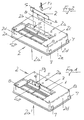
- FIGS. 1 and 2 show first explanatory of the basic structure of the new version in that that on the underside 2a of a cutter housing 2 to the side of the clippings outlet gap "SP" a movable, on the motor limit switch "E” acting flap 1 is arranged.
- the cutting unit housing 2 shown in these FIGS. 1 and 2 is with its underside 2a, which in itself is a Clippings container is facing upwards - i.e. on lying upside down - shown so that the switching flap 1 better is visible.
- connection points 3, 4 and 5, 6 in the Housing underside 2a is insertable, immediately above the Plug connections 3, 4 and 5, 6 one over their whole Has length 4 extending resilient hinge "B" and on their side facing away from the clippings outlet gap "SP" 1 a one as switching cams for the actuation of the Actuating stop switch "E" Rib “S” or the like.
- the directly on the plug connections 3 and 4 subsequent joint point "B" in that shown in Figure 2 Representation, located above the connection points 3 and 4.
- the pluggable connection points as non-positive Snap connections 3 and positive guide pins 4 sit on the bottom of the switch flap facing the housing 1 b Housing underside 2a corresponding thereto Has recesses 5 and 6 and which, with respect to the Representation viewed in Fig. 2, immediately above the Plug connections 3, 4 and 5, 6 parallel to Housing underside 2a extending resilient hinge point as so-called bending groove "B" is introduced into the material thickness "D".
- the Restoring force of the switching flap 1 is thus about the elasticity and geometry of the material in question, so that neither additional reset elements nor bearings or Control lever including transmission linkage prone to failure are required for the new solution.
- Centering pins 7 and 8 on the housing sides 2d serve together the housing flange 2e for fixing the cutter housing 2 on a suitably trained, clippings not shown here.
Landscapes
- Engineering & Computer Science (AREA)
- Food Science & Technology (AREA)
- Crushing And Pulverization Processes (AREA)
Description
- Fig. 1
- in perspektivischer Darstellung ein Aktenvernichter-Schneidwerksgehäuse mit der neuen Schaltklappe von unten betrachtet,
- Fig. 2
- die gleiche Ansicht mit noch nicht eingesetzter Schaltklappe,
- Fig. 3
- die neue Schaltklappe als Einzelteil. in gegenüber Fig. 1 vergrößertem Maßstab in Ansicht,
- Fig. 4
- eine Draufsicht zu Fig. 3 und
- Fig. 5
- eine Schnittdarstellung zu Fig. 3 gemäß der dortigen Linie AB.
- 1
- Schaltklappe
- 1a
- Oberfläche (auf der dem Schnittgutaustrittsspalt "SP" abgewandten Seite)
- 1b
- Unterkante
- 2
- Schneidwerksgehäuse
- 2a
- Gehäuseunterseite
- 2a'
- Gehäuseoberseite
- 2b
- Aussparung
- 2c
- Oberfläche der Gehäuseunterseite
- 2d
- Gehäuseseite
- 2e
- Gehäuseflansch
- 3
- Schnappverbinder
- 4
- Führungszapfen
- 5
- Aussparung für Schnappverbinder
- 6
- Aussparung für Führungszapfen
- 7
- Zentrierzapfen
- 8
- Zentrierzapfen
- B
- Biegenut
- D
- Materialdicke der Schaltklappe
- E
- Endschalter
- L
- Länge der Schaltklappe
- P1
- Einsteckrichtung der Klappe
- P2
- Schwenkrichtung der Klappe
- R
- Anschlagrippe
- S
- Schaltnocken
- SP
- Schnittgutaustrittsspalt
Claims (5)
- Schaltklappe für die Antriebs-Stillsetzung der Schneidwerke von Aktenvernichtern o.ä. Geräten, wobei das jeweilige Schneidwerk in einem auf einem Schnittgutsammelbehälter aufsetzbaren Schneidwerkgehäuse mit einer Gehäuseunterseite untergebracht und die Schaltklappe an der Gehäuseunterseite im Bereich seitlich des Schnittgutaustrittspaltes angeordnet werden kann,
dadurch gekennzeichnet, dass
die Schaltklappe (1) über entsprechende Anschlußstellen (3, 4 und 5, 6) in die Gehäuseunterseite (2a) einsteckbar ist,
an der Schaltklappe (1) sich unmittelbar an die Anschlussstellen (3, 4) anschließend eine sich über ihre ganze Länge (L) erstreckende federnde Gelenkstelle (B) vorgesehen und selbige (B) als sog. Biegenut (B) in die Materialdicke (D) eingebracht ist,
und auf ihrer (1) dem Schnittgutaustrittsspalt (SP) abgewandten Seite (1a) eine als Schaltnocken für die Betätigung des die Antriebsstillsetzung bewirkenden Endschalters (E) dienende Rippe (S) trägt. - Schneidwerksgehäuse (2) eines Aktenvernichters, das mit seiner Unterseite (2a) auf einen Schnittgutsammelbehälter von selbigen aufsetzbar ist, mit einer Schaltklappe nach Anspruch 1
dadurch gekennzeichnet, dass
die steckbaren Anschlussstellen als kraftschlüssige Schnappverbindungen (3) und formschlüssige Führungszapfen (4) an der Schaltklappenkante (1b), die der Gehäuseunterseite (2a) zugewandt ist, sitzen und die Gehäuseunterseite (2a) dazu korrespondierende Aussparungen (5 und 6) aufweist. - Schneidwerksgehäuse (2) eines Aktenvernichters nach Anspruch 2,
dadurch gekennzeichnet, dass
der Schaltnocken (S) durch eine Aussparung (2b) an der Gehäuseunterseite (2a) auf den Endschalter (E) wirkt und die Bewegung der Schaltklappe (1) in Richtung auf den Endschalter (E) durch eine sich an die Oberfläche (2c) der Gehäuseunterseite (2a) in ihrer Endstellung anliegende weitere Rippe (R) begrenzt ist. - Schaltklappe nach Anspruch 1
dadurch gekennzeichnet, dass Schaltnocken (S) und Begrenzungsrippe (R) auf der gleichen Oberfläche (1a) der Schaltklappe (1) sowie auf der der Schaltklappenkante (1b) abgewandten Seite der Biegenut (B) sitzen. - Schaltklappe nach Anspruch 4,
gekennzeichnet durch
Ausbildung der Schaltklappe (1) samt Biegenut (B), Schaltnocken (S), Rippe (R) und steckbaren Anschlussstellen (3 und 4) als einstückiges Kunststoffformteil ohne mechanische Nachbearbeitung.
Applications Claiming Priority (2)
| Application Number | Priority Date | Filing Date | Title |
|---|---|---|---|
| DE19641934 | 1996-10-11 | ||
| DE19641934A DE19641934C2 (de) | 1996-10-11 | 1996-10-11 | Schaltklappe für die Antriebsstillsetzung der Schneidwerke von Aktenvernichtern u. ä. Geräten |
Publications (2)
| Publication Number | Publication Date |
|---|---|
| EP0836886A1 EP0836886A1 (de) | 1998-04-22 |
| EP0836886B1 true EP0836886B1 (de) | 2003-10-08 |
Family
ID=7808453
Family Applications (1)
| Application Number | Title | Priority Date | Filing Date |
|---|---|---|---|
| EP97117388A Expired - Lifetime EP0836886B1 (de) | 1996-10-11 | 1997-10-08 | Schaltklappe für die Antriebsstillsetzung der Schneidwerke von Aktenvernichtern u.ä. Geräten |
Country Status (3)
| Country | Link |
|---|---|
| US (1) | US5969310A (de) |
| EP (1) | EP0836886B1 (de) |
| DE (2) | DE19641934C2 (de) |
Families Citing this family (14)
| Publication number | Priority date | Publication date | Assignee | Title |
|---|---|---|---|---|
| US7025293B2 (en) * | 2004-04-21 | 2006-04-11 | Fellows Inc. | Shredder with pivoting housing for the shredder mechanism |
| US7195185B2 (en) * | 2004-11-02 | 2007-03-27 | Fellowes, Inc. | Shredder with separate waste opening |
| TWM314070U (en) * | 2006-11-30 | 2007-06-21 | Michilin Prosperity Co Ltd | Safety plate for paper feeding of movable shredder machine |
| CN201002037Y (zh) * | 2006-12-28 | 2008-01-09 | 世庆实业股份有限公司 | 碎纸机入纸口触停安全装置 |
| CN201002039Y (zh) * | 2007-01-11 | 2008-01-09 | 世庆实业股份有限公司 | 碎纸机的活动式入纸口盖板 |
| US7757985B2 (en) * | 2007-06-27 | 2010-07-20 | Aurora Office Equipment Co., Ltd. | Safety shredder |
| CA2640979C (en) | 2007-10-30 | 2011-03-29 | Liangneng Chen | Safety shredder |
| US7648089B2 (en) * | 2007-11-28 | 2010-01-19 | Michilin Prosperity Co., Ltd. | Shredder safety interlock switch activation tab |
| US8028942B2 (en) * | 2008-08-01 | 2011-10-04 | Fellowes, Inc. | Bin full detection with light intensity sensing |
| CN101623664B (zh) * | 2009-07-31 | 2013-03-20 | 上海震旦办公设备有限公司 | 碎纸机入纸口安全防护装置 |
| DE102012100681B4 (de) | 2012-01-27 | 2022-09-01 | Hermann Schwelling | Aktenvernichter mit Turbofunktion |
| US8967510B2 (en) | 2012-09-27 | 2015-03-03 | Aurora Office Equipment Co., Ltd. | Safety shredder |
| US9643190B2 (en) | 2013-03-26 | 2017-05-09 | Aurora Office Equipment Co., Ltd. Shanghai | Safety shredder with bin-full device and time delay |
| US10639642B2 (en) * | 2015-03-19 | 2020-05-05 | Aurora Office Equipment Co., Ltd. Shanghai | Shredder jam clear apparatus |
Family Cites Families (11)
| Publication number | Priority date | Publication date | Assignee | Title |
|---|---|---|---|---|
| US3632918A (en) * | 1969-08-25 | 1972-01-04 | Dickey John Corp | Sensing switch construction |
| US3867591A (en) * | 1974-01-16 | 1975-02-18 | Whirlpool Co | One piece switch holder and foot operated hinge actuator for vacuum cleaner switch |
| JPS57152725U (de) * | 1981-03-20 | 1982-09-25 | ||
| DE3312991A1 (de) * | 1983-04-12 | 1984-10-18 | Feinwerktechnik Schleicher & Co, 7778 Markdorf | Vorrichtung zum zerkleinern von materialien, wie dokumenten etc. |
| DE8526418U1 (de) * | 1985-09-16 | 1986-02-13 | Robert Stahlschmidt RST Motorenwerk GmbH, 4800 Bielefeld | Gerät mit umlaufendem Werkzeug |
| DE3706623A1 (de) * | 1987-03-02 | 1988-09-15 | Hermann Schwelling | Verfahren zur selbsttaetigen antriebsabschaltung des schneidwerks eines aktenvernichters bei gefuelltem abfallsammelsack und vorrichtung zur verfahrensdurchfuehrung |
| DE3835450C2 (de) * | 1988-10-18 | 1995-09-14 | Hsm Pressen Gmbh | Schutzsabdeckung für einen mit einer Ballenpresse kombinierten Aktenvernichter |
| DE8911848U1 (de) * | 1989-10-04 | 1990-02-08 | Schwelling, Hermann, 7777 Salem, De | |
| DE4103950C1 (de) * | 1991-02-09 | 1992-04-23 | Geha-Werke Gmbh, 3000 Hannover, De | |
| JP3293329B2 (ja) * | 1994-06-20 | 2002-06-17 | 松下電器産業株式会社 | シュレッダ |
| DE29604761U1 (de) * | 1996-03-14 | 1996-05-09 | Schleicher & Co Int | Schriftgutvernichter |
-
1996
- 1996-10-11 DE DE19641934A patent/DE19641934C2/de not_active Expired - Fee Related
-
1997
- 1997-10-08 EP EP97117388A patent/EP0836886B1/de not_active Expired - Lifetime
- 1997-10-08 DE DE59710829T patent/DE59710829D1/de not_active Expired - Fee Related
- 1997-10-10 US US08/949,087 patent/US5969310A/en not_active Expired - Fee Related
Also Published As
| Publication number | Publication date |
|---|---|
| DE59710829D1 (de) | 2003-11-13 |
| EP0836886A1 (de) | 1998-04-22 |
| US5969310A (en) | 1999-10-19 |
| DE19641934C2 (de) | 1999-06-24 |
| DE19641934A1 (de) | 1998-04-16 |
Similar Documents
| Publication | Publication Date | Title |
|---|---|---|
| EP0836886B1 (de) | Schaltklappe für die Antriebsstillsetzung der Schneidwerke von Aktenvernichtern u.ä. Geräten | |
| DE19717918C2 (de) | Sicherheitsschalter für Aktenvernichter | |
| DE60012471T2 (de) | Elektrisches mischgerät | |
| DE19706736C1 (de) | Betätigungsvorrichtung für ein Heizkörperventil | |
| EP0098894A1 (de) | Elektrisches Schaltgerät, insbesondere Schütz | |
| DE4004656C1 (de) | ||
| EP0268692B1 (de) | Elektrischer Kippschalter | |
| EP2326161B1 (de) | Akku-gartenschere | |
| DE3242152A1 (de) | Kofferschloss, insbesondere aktenkofferschloss | |
| DE19652975C2 (de) | Endschalter für einen Jalousieantrieb | |
| DE69825011T2 (de) | Verbesserungen einer Vorrichtung zur Kontrolle des Auslassventils eines Spülkastens | |
| EP1479284B1 (de) | Elektromotorisch betriebene Grasschere | |
| DE60130509T2 (de) | Steuerventilbehälter für ein Mehrwegeventil | |
| DE3822325C1 (de) | ||
| DE102013114918A1 (de) | Medizintechnische Fußsteuerung | |
| DE69931229T2 (de) | Stufenschalter für elektrische Transformatoren | |
| DE3335139A1 (de) | Kuechenmaschine mit einem sicherheitsschalter | |
| EP1239502A2 (de) | Schalter, insbesondere elektrischer Fensterhebe- oder Schiebedachschalter für Fahrzeuge, Schaltsystem und Verfahren hierzu | |
| DE7902486U1 (de) | Elektrohaushaltsgerät, wie Kaffeemühle | |
| DE4328395C2 (de) | Tastenmodul | |
| DE2949928C2 (de) | Gerät zum Entsteinen von Steinobst, wie Kirschen und Pflaumen | |
| DE3339036A1 (de) | Elektrische schaltvorrichtung | |
| DE1228478B (de) | Schieberventil | |
| EP1239497A1 (de) | Schalter, insbesondere Schalter für Kraftfahrzeuge | |
| DE202007013051U1 (de) | Umschaltvorrichtung für den Wasserfluss eines Zahnrad-Sprengers |
Legal Events
| Date | Code | Title | Description |
|---|---|---|---|
| PUAI | Public reference made under article 153(3) epc to a published international application that has entered the european phase |
Free format text: ORIGINAL CODE: 0009012 |
|
| AK | Designated contracting states |
Kind code of ref document: A1 Designated state(s): DE ES FR GB IT |
|
| 17P | Request for examination filed |
Effective date: 19981002 |
|
| AKX | Designation fees paid |
Free format text: DE ES FR GB IT |
|
| RBV | Designated contracting states (corrected) |
Designated state(s): DE ES FR GB IT |
|
| 17Q | First examination report despatched |
Effective date: 20001124 |
|
| GRAH | Despatch of communication of intention to grant a patent |
Free format text: ORIGINAL CODE: EPIDOS IGRA |
|
| GRAS | Grant fee paid |
Free format text: ORIGINAL CODE: EPIDOSNIGR3 |
|
| GRAA | (expected) grant |
Free format text: ORIGINAL CODE: 0009210 |
|
| AK | Designated contracting states |
Kind code of ref document: B1 Designated state(s): DE ES FR GB IT |
|
| PG25 | Lapsed in a contracting state [announced via postgrant information from national office to epo] |
Ref country code: IT Free format text: LAPSE BECAUSE OF FAILURE TO SUBMIT A TRANSLATION OF THE DESCRIPTION OR TO PAY THE FEE WITHIN THE PRESCRIBED TIME-LIMIT;WARNING: LAPSES OF ITALIAN PATENTS WITH EFFECTIVE DATE BEFORE 2007 MAY HAVE OCCURRED AT ANY TIME BEFORE 2007. THE CORRECT EFFECTIVE DATE MAY BE DIFFERENT FROM THE ONE RECORDED. Effective date: 20031008 Ref country code: GB Free format text: LAPSE BECAUSE OF FAILURE TO SUBMIT A TRANSLATION OF THE DESCRIPTION OR TO PAY THE FEE WITHIN THE PRESCRIBED TIME-LIMIT Effective date: 20031008 Ref country code: FR Free format text: LAPSE BECAUSE OF FAILURE TO SUBMIT A TRANSLATION OF THE DESCRIPTION OR TO PAY THE FEE WITHIN THE PRESCRIBED TIME-LIMIT Effective date: 20031008 |
|
| REG | Reference to a national code |
Ref country code: GB Ref legal event code: FG4D Free format text: NOT ENGLISH |
|
| REF | Corresponds to: |
Ref document number: 59710829 Country of ref document: DE Date of ref document: 20031113 Kind code of ref document: P |
|
| PG25 | Lapsed in a contracting state [announced via postgrant information from national office to epo] |
Ref country code: ES Free format text: LAPSE BECAUSE OF FAILURE TO SUBMIT A TRANSLATION OF THE DESCRIPTION OR TO PAY THE FEE WITHIN THE PRESCRIBED TIME-LIMIT Effective date: 20040119 |
|
| GBV | Gb: ep patent (uk) treated as always having been void in accordance with gb section 77(7)/1977 [no translation filed] |
Effective date: 20031008 |
|
| PG25 | Lapsed in a contracting state [announced via postgrant information from national office to epo] |
Ref country code: DE Free format text: LAPSE BECAUSE OF NON-PAYMENT OF DUE FEES Effective date: 20040501 |
|
| PLBE | No opposition filed within time limit |
Free format text: ORIGINAL CODE: 0009261 |
|
| STAA | Information on the status of an ep patent application or granted ep patent |
Free format text: STATUS: NO OPPOSITION FILED WITHIN TIME LIMIT |
|
| 26N | No opposition filed |
Effective date: 20040709 |
|
| EN | Fr: translation not filed |