EP0835708B1 - Universal-Fräs- und Bohrmaschine - Google Patents
Universal-Fräs- und Bohrmaschine Download PDFInfo
- Publication number
- EP0835708B1 EP0835708B1 EP97115531A EP97115531A EP0835708B1 EP 0835708 B1 EP0835708 B1 EP 0835708B1 EP 97115531 A EP97115531 A EP 97115531A EP 97115531 A EP97115531 A EP 97115531A EP 0835708 B1 EP0835708 B1 EP 0835708B1
- Authority
- EP
- European Patent Office
- Prior art keywords
- boring machine
- universal milling
- machine according
- bracket
- milling
- Prior art date
- Legal status (The legal status is an assumption and is not a legal conclusion. Google has not performed a legal analysis and makes no representation as to the accuracy of the status listed.)
- Expired - Lifetime
Links
- 238000003801 milling Methods 0.000 title claims description 28
- 238000005553 drilling Methods 0.000 description 14
- 210000000078 claw Anatomy 0.000 description 9
- 238000012545 processing Methods 0.000 description 8
- 238000003754 machining Methods 0.000 description 6
- 238000012544 monitoring process Methods 0.000 description 6
- 230000036961 partial effect Effects 0.000 description 5
- 239000012530 fluid Substances 0.000 description 4
- 238000007789 sealing Methods 0.000 description 4
- 230000000007 visual effect Effects 0.000 description 4
- 239000002826 coolant Substances 0.000 description 3
- 238000012546 transfer Methods 0.000 description 3
- 230000002349 favourable effect Effects 0.000 description 2
- 238000010276 construction Methods 0.000 description 1
- 238000005520 cutting process Methods 0.000 description 1
- 238000013461 design Methods 0.000 description 1
- 238000001514 detection method Methods 0.000 description 1
- 238000006073 displacement reaction Methods 0.000 description 1
- 230000002401 inhibitory effect Effects 0.000 description 1
- 238000004519 manufacturing process Methods 0.000 description 1
- 239000002184 metal Substances 0.000 description 1
- 238000007639 printing Methods 0.000 description 1
- 230000001681 protective effect Effects 0.000 description 1
- 230000002829 reductive effect Effects 0.000 description 1
- 239000007787 solid Substances 0.000 description 1
- 230000007704 transition Effects 0.000 description 1
Images

Classifications
-
- B—PERFORMING OPERATIONS; TRANSPORTING
- B23—MACHINE TOOLS; METAL-WORKING NOT OTHERWISE PROVIDED FOR
- B23Q—DETAILS, COMPONENTS, OR ACCESSORIES FOR MACHINE TOOLS, e.g. ARRANGEMENTS FOR COPYING OR CONTROLLING; MACHINE TOOLS IN GENERAL CHARACTERISED BY THE CONSTRUCTION OF PARTICULAR DETAILS OR COMPONENTS; COMBINATIONS OR ASSOCIATIONS OF METAL-WORKING MACHINES, NOT DIRECTED TO A PARTICULAR RESULT
- B23Q1/00—Members which are comprised in the general build-up of a form of machine, particularly relatively large fixed members
- B23Q1/25—Movable or adjustable work or tool supports
- B23Q1/44—Movable or adjustable work or tool supports using particular mechanisms
- B23Q1/56—Movable or adjustable work or tool supports using particular mechanisms with sliding pairs only, the sliding pairs being the first two elements of the mechanism
- B23Q1/60—Movable or adjustable work or tool supports using particular mechanisms with sliding pairs only, the sliding pairs being the first two elements of the mechanism two sliding pairs only, the sliding pairs being the first two elements of the mechanism
- B23Q1/62—Movable or adjustable work or tool supports using particular mechanisms with sliding pairs only, the sliding pairs being the first two elements of the mechanism two sliding pairs only, the sliding pairs being the first two elements of the mechanism with perpendicular axes, e.g. cross-slides
- B23Q1/621—Movable or adjustable work or tool supports using particular mechanisms with sliding pairs only, the sliding pairs being the first two elements of the mechanism two sliding pairs only, the sliding pairs being the first two elements of the mechanism with perpendicular axes, e.g. cross-slides a single sliding pair followed perpendicularly by a single sliding pair
- B23Q1/625—Movable or adjustable work or tool supports using particular mechanisms with sliding pairs only, the sliding pairs being the first two elements of the mechanism two sliding pairs only, the sliding pairs being the first two elements of the mechanism with perpendicular axes, e.g. cross-slides a single sliding pair followed perpendicularly by a single sliding pair followed parallelly by a single rotating pair
-
- B—PERFORMING OPERATIONS; TRANSPORTING
- B23—MACHINE TOOLS; METAL-WORKING NOT OTHERWISE PROVIDED FOR
- B23B—TURNING; BORING
- B23B31/00—Chucks; Expansion mandrels; Adaptations thereof for remote control
- B23B31/02—Chucks
- B23B31/24—Chucks characterised by features relating primarily to remote control of the gripping means
- B23B31/26—Chucks characterised by features relating primarily to remote control of the gripping means using mechanical transmission through the working-spindle
- B23B31/261—Chucks characterised by features relating primarily to remote control of the gripping means using mechanical transmission through the working-spindle clamping the end of the toolholder shank
-
- B—PERFORMING OPERATIONS; TRANSPORTING
- B23—MACHINE TOOLS; METAL-WORKING NOT OTHERWISE PROVIDED FOR
- B23Q—DETAILS, COMPONENTS, OR ACCESSORIES FOR MACHINE TOOLS, e.g. ARRANGEMENTS FOR COPYING OR CONTROLLING; MACHINE TOOLS IN GENERAL CHARACTERISED BY THE CONSTRUCTION OF PARTICULAR DETAILS OR COMPONENTS; COMBINATIONS OR ASSOCIATIONS OF METAL-WORKING MACHINES, NOT DIRECTED TO A PARTICULAR RESULT
- B23Q1/00—Members which are comprised in the general build-up of a form of machine, particularly relatively large fixed members
- B23Q1/01—Frames, beds, pillars or like members; Arrangement of ways
- B23Q1/015—Frames, beds, pillars
-
- B—PERFORMING OPERATIONS; TRANSPORTING
- B23—MACHINE TOOLS; METAL-WORKING NOT OTHERWISE PROVIDED FOR
- B23Q—DETAILS, COMPONENTS, OR ACCESSORIES FOR MACHINE TOOLS, e.g. ARRANGEMENTS FOR COPYING OR CONTROLLING; MACHINE TOOLS IN GENERAL CHARACTERISED BY THE CONSTRUCTION OF PARTICULAR DETAILS OR COMPONENTS; COMBINATIONS OR ASSOCIATIONS OF METAL-WORKING MACHINES, NOT DIRECTED TO A PARTICULAR RESULT
- B23Q1/00—Members which are comprised in the general build-up of a form of machine, particularly relatively large fixed members
- B23Q1/25—Movable or adjustable work or tool supports
- B23Q1/26—Movable or adjustable work or tool supports characterised by constructional features relating to the co-operation of relatively movable members; Means for preventing relative movement of such members
-
- B—PERFORMING OPERATIONS; TRANSPORTING
- B23—MACHINE TOOLS; METAL-WORKING NOT OTHERWISE PROVIDED FOR
- B23Q—DETAILS, COMPONENTS, OR ACCESSORIES FOR MACHINE TOOLS, e.g. ARRANGEMENTS FOR COPYING OR CONTROLLING; MACHINE TOOLS IN GENERAL CHARACTERISED BY THE CONSTRUCTION OF PARTICULAR DETAILS OR COMPONENTS; COMBINATIONS OR ASSOCIATIONS OF METAL-WORKING MACHINES, NOT DIRECTED TO A PARTICULAR RESULT
- B23Q5/00—Driving or feeding mechanisms; Control arrangements therefor
- B23Q5/54—Arrangements or details not restricted to group B23Q5/02 or group B23Q5/22 respectively, e.g. control handles
-
- Y—GENERAL TAGGING OF NEW TECHNOLOGICAL DEVELOPMENTS; GENERAL TAGGING OF CROSS-SECTIONAL TECHNOLOGIES SPANNING OVER SEVERAL SECTIONS OF THE IPC; TECHNICAL SUBJECTS COVERED BY FORMER USPC CROSS-REFERENCE ART COLLECTIONS [XRACs] AND DIGESTS
- Y10—TECHNICAL SUBJECTS COVERED BY FORMER USPC
- Y10T—TECHNICAL SUBJECTS COVERED BY FORMER US CLASSIFICATION
- Y10T408/00—Cutting by use of rotating axially moving tool
- Y10T408/55—Cutting by use of rotating axially moving tool with work-engaging structure other than Tool or tool-support
- Y10T408/561—Having tool-opposing, work-engaging surface
- Y10T408/5614—Angularly adjustable surface
-
- Y—GENERAL TAGGING OF NEW TECHNOLOGICAL DEVELOPMENTS; GENERAL TAGGING OF CROSS-SECTIONAL TECHNOLOGIES SPANNING OVER SEVERAL SECTIONS OF THE IPC; TECHNICAL SUBJECTS COVERED BY FORMER USPC CROSS-REFERENCE ART COLLECTIONS [XRACs] AND DIGESTS
- Y10—TECHNICAL SUBJECTS COVERED BY FORMER USPC
- Y10T—TECHNICAL SUBJECTS COVERED BY FORMER US CLASSIFICATION
- Y10T409/00—Gear cutting, milling, or planing
- Y10T409/30—Milling
- Y10T409/306664—Milling including means to infeed rotary cutter toward work
- Y10T409/307448—Milling including means to infeed rotary cutter toward work with work holder
- Y10T409/307504—Indexable
-
- Y—GENERAL TAGGING OF NEW TECHNOLOGICAL DEVELOPMENTS; GENERAL TAGGING OF CROSS-SECTIONAL TECHNOLOGIES SPANNING OVER SEVERAL SECTIONS OF THE IPC; TECHNICAL SUBJECTS COVERED BY FORMER USPC CROSS-REFERENCE ART COLLECTIONS [XRACs] AND DIGESTS
- Y10—TECHNICAL SUBJECTS COVERED BY FORMER USPC
- Y10T—TECHNICAL SUBJECTS COVERED BY FORMER US CLASSIFICATION
- Y10T409/00—Gear cutting, milling, or planing
- Y10T409/30—Milling
- Y10T409/30868—Work support
- Y10T409/308792—Indexable
-
- Y—GENERAL TAGGING OF NEW TECHNOLOGICAL DEVELOPMENTS; GENERAL TAGGING OF CROSS-SECTIONAL TECHNOLOGIES SPANNING OVER SEVERAL SECTIONS OF THE IPC; TECHNICAL SUBJECTS COVERED BY FORMER USPC CROSS-REFERENCE ART COLLECTIONS [XRACs] AND DIGESTS
- Y10—TECHNICAL SUBJECTS COVERED BY FORMER USPC
- Y10T—TECHNICAL SUBJECTS COVERED BY FORMER US CLASSIFICATION
- Y10T409/00—Gear cutting, milling, or planing
- Y10T409/30—Milling
- Y10T409/30868—Work support
- Y10T409/30896—Work support with angular adjustment
-
- Y—GENERAL TAGGING OF NEW TECHNOLOGICAL DEVELOPMENTS; GENERAL TAGGING OF CROSS-SECTIONAL TECHNOLOGIES SPANNING OVER SEVERAL SECTIONS OF THE IPC; TECHNICAL SUBJECTS COVERED BY FORMER USPC CROSS-REFERENCE ART COLLECTIONS [XRACs] AND DIGESTS
- Y10—TECHNICAL SUBJECTS COVERED BY FORMER USPC
- Y10T—TECHNICAL SUBJECTS COVERED BY FORMER US CLASSIFICATION
- Y10T409/00—Gear cutting, milling, or planing
- Y10T409/30—Milling
- Y10T409/30952—Milling with cutter holder
Definitions
- the invention relates to a universal milling and drilling machine according to the preamble of claim 1.
- Swivel rotary tables or swiveling spindles or stands 5-axis machining of a workpiece in one setup which saves the time required for reclamping and the manufacturing accuracy can be improved.
- Swivel rotary tables are often used as separate additional units offered on the workpiece table if necessary be spanned.
- the construction of such Machine tool and in particular the control of all traversing and pivoting movements is relatively complex.
- Swivel tables the problem that with certain inclinations of the work table the processing point from Control panel of the control is no longer visible. Thereby is monitoring the machining process, in particular when moving a tool to the workpiece via manual control, difficult.
- a machine tool according to the preamble of Claim 1 is known from EP 0 463 453.
- the object of the invention is a compact and inexpensive Universal milling and drilling machine to create with relatively low control engineering effort Multi-axis processing and control with optimal Visual contact to the processing point enabled.
- the swiveling rotary table By the opposite of the central axis of the milling and drilling machine staggered arrangement of the swiveling rotary table is an enlargement of the work area in the X axis double the amount of the transfer possible.
- the position of the turntable can be changed by turning the Workpiece machined by 180 ° also workpieces in one clamping that will be double the amount of the transfer larger than that due to the maximum movement of the cross slide specified distance between the two end positions the work spindle.
- the table can be swiveled in certain ways Oblique positions of the workpiece occur in which the point of engagement of the tool on the workpiece from the actual one Control panel is no longer visible. In this case the portable control panel carried by the operator or on a cheap one for monitoring the tool intervention Place on the machine to be certain Functional sequences of the machine with optimal visual contact to control the processing point.
- the portable control panel handwheels for controlling the movement arranged in the three main axes can also be moved using handwheels, which is particularly useful for a set-up operation or for starting the tool to the workpiece with unfavorable visibility from Advantage is.
- handwheels for the control can be made in the control panel Components such as Emergency stop switch, controls for Coolant supply, or other switching elements and displays be installed.
- control panel For easy attachment of the portable control panel to the Control panel of the control or at any, for monitoring the processing point at favorable locations on the machine stand the control panel is advantageously in one magnetic or magnetic housings accommodated.
- the universal milling and drilling machine is the work spindle surrounding cylinder-piston unit with a Ring piston for actuating an integrated in the work spindle Tool clamps arranged.
- the working spindle arranged pressure piston can the length of the headstock thereby be reduced.
- the clamping or releasing position of the tool clamp can be monitor advantageously via limit switches that by a switching disc coupled to the ring piston without contact can be operated. Compared to conventional The solid switching disc enables switching pins to be more reliable Monitoring.
- a stable connection between the swiveling rotary table and the machine stand is surrounded by a circular Foot of the console reached in a corresponding recess is rotatably supported on the machine stand.
- clamping elements are provided on the console, via which the console opposite the machine stand can be braced.
- the rotation of the console and the turntable Actuators that can be operated via handwheels.
- the Actuator for the rotation of the console can for example be designed as a backdrop or Maltese drive.
- the positioning of the console and the turntable can but also done via separate motors, which via the Control can be activated.
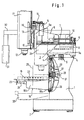
- the universal milling and drilling machine shown in FIGS. 1 and 2 for multi-axis machining of workpieces includes one Machine stand 1, which has adjustable mounting elements 2 stands on a foundation or on the floor.
- a cross slide 3 over perpendicular to the drawing plane of FIG. 1 parallel linear guides 4 can be moved horizontally in the X-axis guided.
- the cross slide 3 is driven by a - not shown - motor via a ball screw 5.
- the cross slide 3 has a continuous Middle part 3a and two spaced side cheeks 3b which a longitudinal slide 6 perpendicular to the plane of the drawing 2 linear guides 7 in the Z axis movable runs.
- the longitudinal slide is driven by a motor 8 6 driven by a toothed belt 9 and a spindle 10.
- the longitudinal slide 6 has a between the two side cheeks 3b arranged front part 6a, on the end face a vertical headstock 11 with a work spindle 12 vertically via guide elements 13 in the Y axis is guided.
- the movement of the headstock 11 is carried out by a motor 14 via a toothed belt 15 and a drive spindle 16.
- a in Fig. 2nd Hand crank 17 shown on the front face of the headstock 11 is the vertical position of the work spindle 12 manually adjustable.
- At the front end of the machine stand 1 is one Console 18 with a workpiece table 19 by means of a 1 actuator 20 shown between a in Fig. 2nd horizontal and solid lines a vertical machining position shown with dashed lines pivotable about a horizontal axis 21 arranged.
- the console 18 has one in the front view 2 circular foot 18a and one to the horizontal Axially parallel cantilevered shoulder 18b on a Support surface 22 the workpiece table designed as a rotary table 19 wears. This is by means of a handwheel 23 actuated actuator 24 about a to the pivot axis 21st vertical axis 25 rotatable.
- the console 18 is over hers circular foot 18a in a corresponding recess 26 supported on the front end of the machine stand 1 and rotatably guided on a journal 27.
- the Actuator 20 for pivoting the console 18 is through a hand crank 28 shown in FIG. 2 can be actuated.
- the Pivot position of the console 18 is by a rotary encoder 29 detected, which is coupled to the foot 18a.
- Below the Console 18 is dashed on the machine stand 1 in Fig. 1 Trough 30 shown for collecting the coolant and the machining chips attached.
- the milling and drilling machine shown in FIGS. 1 and 2 is equipped with a numerical control to which a Hand control panel 31 connected to a screen display is.
- the hand control panel 31 is angled Support arm 32 with the machine stand 1 or another load-bearing component connected.
- an additional portable control panel 33 is provided, that e.g. through a magnetic housing 34 or magnetic Holding elements on the underside of the hand control panel 31 or at any, for the monitoring of the processing point favorable, positions on the machine stand 1 can be moved can be, as shown by the dashed lines Positions is indicated.
- the portable control panel 33 includes a handwheel 35 for manual control of the Headstock 11 and the cross and longitudinal slide 3 or 6.
- each handwheel 35 can additionally each a brake can be assigned through which one to the output power of the corresponding drive motor proportional Inhibitory force is exerted on the drive shaft of the handwheel. This allows the operator to feel for the drive motor performance to be exerted and thus the burden of the tool.
- the control panel 33 the tool accommodated in the work spindle, e.g.
- control panel 33 Due to the portable design of the control panel 33, this can be done by the operator carried or on one to monitor the tool intervention convenient location on the machine stand, in order to control the processing or possibly Intervention in the program flow with visual monitoring the processing point even with limited visibility, e.g. due to an inclined position of the workpiece table, to enable.
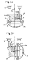
- the console 18 is arranged in such a way that its pivot axis 21 relative to the central axis 36 of the drilling and milling machine is laterally offset. Thereby is also the one centrally arranged on the console Turntable 19 offset to the central axis 36. This makes possible an enlargement of the working area, as shown in FIGS. 3A and 3B.
- Fig. 3A is a rotary table 37 with its for Laterally offset the central axis 36 of the milling and drilling machine Swivel axis 21 and the horizontal position of the workpiece table 19 shown.
- the Console 18 a circular segment-shaped foot 18a.
- At the top 3A are also the two by the travel of the cross slide 3 predetermined end positions of the Work spindle 12 shown. Because of these two end positions can be a centrally clamped on the workpiece table 19 Workpiece 38 with the outline shown in the illustrated Horizontal position of the swivel rotary table 37 within of the partial area shown hatched in FIG. 3A 39 can be edited.
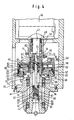
- the work spindle 12 designed as a hollow shaft with an integrated Tool clamp 41 is the one in FIGS. 4 and 5 shown headstock 11 from a bearing arrangement Angular contact ball bearing pairs 42 braced against one another in a tandem O arrangement rotatably supported in a spindle sleeve 43, which has a flange 44 on the front end of a Headstock housing 45 is attached.
- 4 and 5 is the tool clamp 41 in the left half of the picture in the clamping position and in the right half of the picture in the Release position shown.
- the work spindle 12 is by a Motor coaxially arranged in the headstock housing 45 46 driven, on the output shaft 47 with two opposite claws 48 provided connector 49 arranged in a rotationally fixed manner by means of an adapter sleeve 50 is.
- the two opposite claws 48 grip Transfer of the rotary movement into corresponding recesses 51 at the inner end of the work spindle 12 like this 4 can be seen.
- the spindle sleeve 43 has in her in the headstock housing 45 protruding inner end part an annular recess 52, in which the slimmer part 53 of a coaxial to the work spindle stepped annular piston 54 is guided.
- the part 55 of the annular piston 54 with the larger diameter is displaceable in an annular space 56 designed as a pressure chamber, by one on the inner end face 57 of the Spindle sleeve 43 screwed cover 58 is limited.
- a pressure fluid line 59 leads through the cover 58 Pressurizing the annular piston 54 in the extension direction.
- the end face 60 at the transition from the slimmer to the extended Part of the annular piston 54 serves as a piston surface for Pressurization of the annular piston 54 in the retracting direction, to which a pressure fluid line 61 in the spindle sleeve 43 leads.
- the annular piston 54 is opposite to the cover 58 Sealing rings 62 and against the inner wall of the annular Recess 52 sealed by a sealing ring 63.
- a sliding bush 68 arranged axially displaceably on the work spindle 12.
- the sliding bush 68 has at its lower end in FIG. 4 a ring collar 69, which is set back against one End face 70 formed on the slimmer part of the annular piston 54 is.
- the sliding bushing 68 at its top in the illustration End part 71 two opposite recesses 72 for the two claws 48 of the connecting bush 49.
- the tool clamp 41 contains a clamping bush 83, which on front end of the in a central longitudinal bore 84 of the Work spindle 12 slidably arranged tension rod 77 is attached.
- a clamping bush 83 In an annular groove 85 at the front end of the Clamping bushing 83 are gripping claws 86 which are pivotally mounted inclined outer surfaces 87 in the clamping position by one Projection 88 on the inner wall of the work spindle 12 for Engagement of the gripping claws 86 in a corresponding groove Tool or a tool holder pressed inwards are.
- the gripping claws 86 with their inclined outer surfaces 87 of a spring element, not shown spread outwards in an extended area In the release position, the gripping claws 86 with their inclined outer surfaces 87 of a spring element, not shown spread outwards in an extended area.
- a plate spring assembly 91 is arranged between a ring shoulder 89 and a conical outgoing pressure piece 90.
- balls 92 On the outside of the conical part of the pressure piece 90 run balls 92, which on their outside between the inclined surfaces of one in the work spindle 12 ring 93 fixed in position and one by ring collar 79 axially displaceable ring 94 abut.
- On the conical Part of the pressure piece 90 closes on the tension rod Slidable inner ring 95 with a pressure piece 90 facing rounded surface 96 on which the balls 92 in the release position of the tool clamp 41 to the system reach.
- the inner ring 95 is over with the pressure ring 79 Pins 97 connected by axial holes in the collar 79 run.
- the annular space 56 is connected via the line 59 acted upon with a pressure fluid, the annular piston 54 from that in FIGS. 4 and 5 in the left half of the picture shown clamping position in the right Half of the picture shown is moved.
- the annular piston 54 moves the sliding bush 68 and the with this pressure ring coupled via the connecting pins 74 76.
- the inner ring 95 is first of all about the pins 97 and the pressure piece 90 against the force of the plate spring assembly 91 moved, the balls 92 along the conical Slide outer surfaces of thrust piece 90 radially inward.
- the annular space 56 is over the Line 61 pressurized with fluid, the annular piston 54 moved from the loose to the clamping position and the Tension rod 77 under the action of plate spring assembly 91 is drawn in.
- the gripping claws 86 also become Engagement in an annular groove of a tool pressed inwards. Be over the conical surfaces of the pressure piece 90 balls 92 radially outward between the two Sloping surfaces of the rings 93 and 94 to shift the Rings 94 and the collar 79 of the tension rod 77 pressed. This increases the pull-in force.
- the clamping or releasing position of the tool clamp 41 is monitored via the limit switch 82, which by the at the Front side of the sliding bush 68 arranged switching disc 80 are operated.
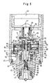
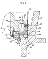
- FIG. 6 is an enlarged partial view of one in FIG. 1 shown type of console bracket on the machine stand 1 shown.
- the foot 18a of the console lies 18 via an inner guide surface 98 on one around the Recess 26 arranged annular contact surface 99 the front end of the machine stand 1 and will held by four clamping pieces 100 distributed over the circumference, by four screws also shown in Fig. 2 101 can be locked and released.
- the rectangular in cross section Clamping pieces 100 engage with their radially outer end part 100a in an annular groove 102 on an inner wall 103 of the Recess 26 in the machine stand 1. With her radial inner end part 100b, the clamping pieces 100 each rest an annular extension 104 of the foot projecting into the recess 26 18a.
- the screws 101 are in through holes 105 arranged in the foot 18a and engage with their front Thread section in a corresponding threaded bore 106 in the respective clamping pieces 100.
- the console 18 By tightening the Screws 101 can the console 18 against the machine stand 1 clamped and in a predetermined swivel position be locked.
- To pivot the console 18 must only loosened the screws 101 and thereby the Clamp to be released.
- the console 18 can then pivoted about the actuator 20 shown in Fig. 1 become.
- the clamping pieces 100 are for mutual position fixation fixed to a sheet metal ring 108 by means of retaining screws 107.
- To prevent dirt or coolant from entering is in the recess 26 in the machine stand 1 the outside of the foot 18a in the area of the guide surface 98 an annular groove 109 is arranged with a sealing ring 110.
- the sealing ring 110 is held by a holding pin 111 scale tape attached to the outside of the foot 18a 112 held at the same time for visual display the pivot position of the console 18 is used.
- the invention is not based on the illustrated embodiment limited. So can the milling and drilling machine also with additional tool magazines and automatic Be provided with tool changers. Also a version with additional protective cabin is possible.
Landscapes
- Engineering & Computer Science (AREA)
- Mechanical Engineering (AREA)
- Drilling And Boring (AREA)
- Machine Tool Units (AREA)
Description
- Fig. 1
- eine Fräs- und Bohrmaschine in schematischer Seitenansicht;
- Fig. 2
- die Fräsmaschine nach Fig. 1 in Vorderansicht;
- Fig. 3A und 3B
- eine schematische Vorderansicht eines Schwenkrundtisches in vertikaler und horizontaler Arbeitsstellung; Fig. 3A und 3B
- Fig. 4
- einen Teilschnitt eines Spindelstocks der erfindungsgemäßen Fräsund Bohrmaschine;
- Fig. 5
- einen Teilschnitt des Spindelstocks von Fig. 4 mit einer um 90° versetzten Schnittebene und
- Fig. 6
- eine vergrößerte Teildarstellung der in Fig. 1 gezeigten Konsolenhalterung im Schnitt.
Claims (11)
- Universal-Fräs- und Bohrmaschine miteinem Maschinenständer (1),einem auf dem Maschinenständer (1) horizontal verfahrbaren Kreuzschlitten (3, 6),einem am Kreuzschlitten (3, 6) vertikal verfahrbar angeordneten Spindelstock (11) mit einer Arbeitsspindel (12),einem über eine Konsole (18) am Maschinenständer (1) verschwenkbar angeordneten Drehtisch (19) undeiner Steuereinheit, wobeidie Konsole (18) um eine horizontale Schwenkachse (21) drehbar am Maschinenständer (1) angeordnet ist, undder Drehtisch (19) um eine zur Schwenkachse (21) senkrechte Drehachse (25) mittig auf der Konsole (18) verdrehbar angeordnet ist,
dadurch gekennzeichnetdaß die Steuereinheit ein portables Steuerpult (33) umfaßt, unddaß die Schwenkachse (21) gegenüber der Mittelachse (36) der Fräs- und Bohrmaschine seitlich versetzt ist. - Universal-Fräs- und Bohrmaschine nach Anspruch 1,
dadurch gekennzeichnet, daß das portable Steuerpult (33) jeweils ein manuell betätigbares Steuerelement (35) für die Verfahrbewegungen des Kreuzschlittens (3, 6) des Spindelstocks (11) aufweist. - Universal-Fräs- und Bohrmaschine nach Anspruch 1 oder 2,
dadurch gekennzeichnet, daß die manuell betätigbaren Steuerelemente als Handräder (35) ausgebildet sind. - Universal-Fräs- und Bohrmaschine nach einem der Ansprüche 1 bis 3,
dadurch gekennzeichnet, daß das portable Steuerpult (33) in einem magnetischen oder mit Magnethaltern versehenen Gehäuse untergebracht ist. - Universal-Fräs- und Bohrmaschine nach einem der Ansprüche 1 bis 4,
dadurch gekennzeichnet, daß in dem Spindelstock (11) eine um die Arbeitsspindel (12) angeordnete Zylinder-Kolben-Einheit (52, 54, 58) mit einem Ringkolben (54) zur Betätigung eines in der Arbeitsspindel (12) integrierten Werkzeugspanners (41) angeordnet ist. - Universal-Fräs- und Bohrmaschine nach Anspruch 5,
dadurch gekennzeichnet, daß der Ringkolben (54) über eine Schiebebuchse (68) und einen mit dieser gekoppelten Druckring (79) mit dem Werkzeugspanner (41) verbunden ist. - Universal-Fräs- und Bohrmaschine nach Anspruch 6,
dadurch gekennzeichnet, daß an der Schiebebuchse (68) eine Schaltscheibe (80) zur berührungslosen Betätigung zweier Endschalter (82) befestigt ist. - Universal-Fräs- und Bohrmaschine nach einem der Ansprüche 1 bis 7,
dadurch gekennzeichnet, daß die Konsole (18) einen kreisrunden Fuß (18a) aufweist, der in einer entsprechenden Ausnehmung (26) am Maschinenständer (1) verdrehbar abgestützt ist. - Universal-Fräs- und Bohrmaschine nach einem der Ansprüche 1 bis 8,
dadurch gekennzeichnet, daß die Konsole (18) und der Drehtisch (19) über manuell betätigbare Stellantriebe (20, 24) verdrehbar sind. - Universal-Fräs- und Bohrmaschine nach einem der Ansprüche 1 bis 9,
dadurch gekennzeichnet, daß die Konsole (18) und der Drehtisch (19) motorisch verdrehbar sind. - Universal-Fräs- und Bohrmaschine nach einem der Ansprüche 1 bis 10,
dadurch gekennzeichnet, daß an der Konsole (18) mehrere am Maschinenständer (1) angreifende Klemmstücke (100) zur lösbaren Klemmung der Konsole in einer gewünschten Schwenkstellung angeordnet sind.
Priority Applications (1)
| Application Number | Priority Date | Filing Date | Title |
|---|---|---|---|
| DE29724723U DE29724723U1 (de) | 1996-10-10 | 1997-09-08 | Universal Fräs- und Bohrmaschine |
Applications Claiming Priority (2)
| Application Number | Priority Date | Filing Date | Title |
|---|---|---|---|
| DE19641831A DE19641831B4 (de) | 1996-10-10 | 1996-10-10 | Universal-Fräs- und Bohrmaschine |
| DE19641831 | 1996-10-10 |
Publications (3)
| Publication Number | Publication Date |
|---|---|
| EP0835708A2 EP0835708A2 (de) | 1998-04-15 |
| EP0835708A3 EP0835708A3 (de) | 1999-02-03 |
| EP0835708B1 true EP0835708B1 (de) | 2003-06-25 |
Family
ID=7808397
Family Applications (1)
| Application Number | Title | Priority Date | Filing Date |
|---|---|---|---|
| EP97115531A Expired - Lifetime EP0835708B1 (de) | 1996-10-10 | 1997-09-08 | Universal-Fräs- und Bohrmaschine |
Country Status (5)
| Country | Link |
|---|---|
| US (1) | US5909988A (de) |
| EP (1) | EP0835708B1 (de) |
| JP (1) | JP3670460B2 (de) |
| DE (2) | DE19641831B4 (de) |
| ES (1) | ES2201234T3 (de) |
Cited By (1)
| Publication number | Priority date | Publication date | Assignee | Title |
|---|---|---|---|---|
| EP2345503A2 (de) | 2010-01-19 | 2011-07-20 | Deckel Maho Seebach GmbH | Werkzeugmaschine |
Families Citing this family (31)
| Publication number | Priority date | Publication date | Assignee | Title |
|---|---|---|---|---|
| EP0904890B1 (de) * | 1997-09-30 | 2004-08-25 | Toyoda Koki Kabushiki Kaisha | Horizontal-Werkzeugmaschine |
| EP1057582B1 (de) * | 1999-05-21 | 2002-09-11 | Maschinenfabrik Berthold Hermle Aktiengesellschaft | Bearbeitungsmaschine, insbesondere Bohr- und/oder Fräsmaschine |
| US6612519B1 (en) | 1999-11-02 | 2003-09-02 | Axis Usa, Inc. | Methods and apparatus for winding electric machine cores |
| US6352496B1 (en) | 2000-01-28 | 2002-03-05 | Imta Manufacturing Technology & Automation Company | High-speed milling machine with rotary table |
| JP2003094264A (ja) * | 2001-09-19 | 2003-04-03 | It Techno Kk | 3軸制御マシニングセンタによる2面加工方法、及びその装置 |
| JP4009237B2 (ja) * | 2003-09-08 | 2007-11-14 | 東邦エンジニアリング株式会社 | 半導体cmp加工用パッドの細溝加工機械 |
| DE102004049525B3 (de) * | 2004-10-11 | 2006-03-16 | Deckel Maho Seebach Gmbh | Werkzeugmaschine |
| KR101252611B1 (ko) | 2005-03-18 | 2013-04-09 | 호코스 가부시키가이샤 | 공작기계 |
| US8210782B2 (en) * | 2005-03-18 | 2012-07-03 | Horkos Corp. | Machine tool |
| KR101295945B1 (ko) * | 2005-07-29 | 2013-08-13 | 코마츠 엔티씨 가부시끼가이샤 | 주축장치에 이용하는 공구홀더 클램프 유닛 |
| JP2007296613A (ja) * | 2006-05-01 | 2007-11-15 | Mori Seiki Co Ltd | 工作機械 |
| GB2445190A (en) * | 2006-12-30 | 2008-07-02 | Joshua Nicholas George Reid | Subtractive Prototyping Machine |
| WO2009144831A1 (ja) * | 2008-05-27 | 2009-12-03 | 株式会社牧野フライス製作所 | 工作機械 |
| DE202009002504U1 (de) * | 2009-02-06 | 2010-06-24 | Hedelius Maschinenfabrik Gmbh | Bearbeitungszentrum |
| IT1396290B1 (it) * | 2009-10-03 | 2012-11-16 | L C M S R L | Procedimento per il corretto posizionamento operativo di una tavola rotante in modo basculante rispetto ad un basamento e mezzi per la sua attuazione. |
| JP2011148010A (ja) * | 2010-01-19 | 2011-08-04 | Yaskawa Electric Corp | ポジショナを備えたロボットシステム |
| DE102010035669A1 (de) * | 2010-08-27 | 2012-03-01 | Datron Ag | Werkzeugmaschine |
| DE102011110834A1 (de) * | 2011-08-23 | 2013-02-28 | Kern Micro- Und Feinwerktechnik Gmbh & Co. Kg | Maschinenständer einer Werkzeugmaschine |
| CN102764919B (zh) * | 2012-07-31 | 2014-07-02 | 武汉大学 | 一种滚铣复合加工机床的控制方法 |
| CN106926003A (zh) * | 2013-09-23 | 2017-07-07 | 苏州怡信光电科技有限公司 | 具有自调整功能的数控切削机床 |
| TWM523536U (zh) * | 2015-11-05 | 2016-06-11 | Factory Automation Technology | 物件毛邊加工機 |
| CN105642932B (zh) * | 2016-03-23 | 2018-08-21 | 西安交通大学 | 一种镗铣复合加工工艺及装置 |
| CN107598213A (zh) * | 2017-10-10 | 2018-01-19 | 安徽古皖刷业有限公司 | 刷盘盘面自动钻孔机床及其使用方法 |
| DE102018124456A1 (de) * | 2018-10-04 | 2020-04-09 | Man Energy Solutions Se | Handhabungsvorrichtung zur Wartung eines Kolbens mit einem an dem Kolben über einen Kolbenbolzen befestigten Pleuelkopf |
| CN109531278B (zh) * | 2019-01-24 | 2024-03-22 | 南京众得利自动化机械有限公司 | 一种集中安装动力头的组合机床 |
| DE102019102158B4 (de) * | 2019-01-29 | 2022-01-20 | Gebr. Heller Maschinenfabrik Gmbh | Plandrehkopf und Verfahren zum Spannen und zum Lösen eines Werkzeugs in bzw. aus einer Werkzeugaufnahmeeinrichtung des Plandrehkopfes |
| CN112407201B (zh) * | 2020-11-17 | 2021-10-29 | 清华大学深圳国际研究生院 | 一种位姿调整工装 |
| US20230075159A1 (en) * | 2021-09-09 | 2023-03-09 | Alex Global Technology, Inc. | Intelligent automatic processing apparatus for spoke hole of bicycle rim |
| KR102573816B1 (ko) * | 2022-04-08 | 2023-08-31 | 김상훈 | 마킹부위의 정밀 홀 가공 장치 |
| CN116213789B (zh) * | 2023-03-03 | 2024-04-02 | 中国核电工程有限公司 | 一种数控镗床及数控镗床系统 |
| CN120326415A (zh) * | 2025-06-19 | 2025-07-18 | 昆明台工精密机械有限公司 | 一种主轴可调节的反向弧门移动式镗铣床 |
Family Cites Families (16)
| Publication number | Priority date | Publication date | Assignee | Title |
|---|---|---|---|---|
| DE245103C (de) * | ||||
| US2651975A (en) * | 1949-05-11 | 1953-09-15 | Soloff Milton | Internal carving machine |
| DE1948464C3 (de) * | 1969-09-25 | 1975-07-31 | Werkzeugmaschinenfabrik Salzgitter Gmbh, 3327 Salzgitter-Bad | Um drei Achsen schwenkbarer Aufspanntisch für Universal-Fräs- und/oder Bohrmaschinen |
| DE2105824C3 (de) * | 1971-02-08 | 1974-07-04 | Max Dr.-Ing. 8700 Wuerzburg Mengeringhausen | Vorrichtung zum Einspannen von Werkstücken für das Bearbeiten an mehreren Umfangsflächen |
| US3746459A (en) * | 1971-03-24 | 1973-07-17 | Overmyer Mould Co | Apparatus for drilling escape and vent holes in die molds |
| DE2328439C3 (de) * | 1973-06-05 | 1975-11-13 | Berthold Hermle Kg, 7209 Gosheim | Schwenkbarer Werkstück-Aufspanntisch für Werkzeugmaschinen, insbesondere für Universal-Fräsmaschinen |
| FR2290981A1 (fr) * | 1974-07-01 | 1976-06-11 | Romeu Ramon | Fraiseuse universelle |
| SE423195B (sv) * | 1977-05-04 | 1982-04-26 | Per Olof Aldrin | Verktygsmaskin av universaltyp |
| DE2833145A1 (de) * | 1978-07-28 | 1980-02-07 | Ewertowski Ing Buero | Waagerecht-bohr-fraesmaschine |
| FR2507935A1 (fr) * | 1981-06-19 | 1982-12-24 | Etu Fraisage Centre | Perfectionnements aux machines-outils a grande productivite |
| JPS6150757A (ja) * | 1984-08-11 | 1986-03-13 | Tsugami Corp | 工作機械の複式割出し装置 |
| GB2188262A (en) * | 1986-03-25 | 1987-09-30 | Buckley & Taylor Limited | Universal manipulator for handling workpieces |
| JPH0279249A (ja) * | 1988-09-16 | 1990-03-19 | Sanyo Electric Co Ltd | 磁気記録再生装置のテープ走行速度制御方法 |
| JPH0457635A (ja) * | 1990-06-25 | 1992-02-25 | Kitamura Mach Co Ltd | 工作機械 |
| EP0558877A1 (de) * | 1992-03-03 | 1993-09-08 | OFFICINE MECCANICHE VARINELLI S.p.A. | Halte- und Positionierungsvorrichtung zum vertikalen Räumen von Schaufellaufrädern |
| DE4444614A1 (de) * | 1994-12-14 | 1996-06-20 | Deckel Maho Gmbh | Werkzeugmaschine |
-
1996
- 1996-10-10 DE DE19641831A patent/DE19641831B4/de not_active Expired - Lifetime
-
1997
- 1997-09-08 ES ES97115531T patent/ES2201234T3/es not_active Expired - Lifetime
- 1997-09-08 DE DE59710336T patent/DE59710336D1/de not_active Expired - Lifetime
- 1997-09-08 EP EP97115531A patent/EP0835708B1/de not_active Expired - Lifetime
- 1997-10-09 US US08/947,992 patent/US5909988A/en not_active Expired - Lifetime
- 1997-10-09 JP JP27747797A patent/JP3670460B2/ja not_active Expired - Fee Related
Cited By (2)
| Publication number | Priority date | Publication date | Assignee | Title |
|---|---|---|---|---|
| EP2345503A2 (de) | 2010-01-19 | 2011-07-20 | Deckel Maho Seebach GmbH | Werkzeugmaschine |
| DE102010004990A1 (de) | 2010-01-19 | 2011-07-21 | Deckel Maho Seebach GmbH, 99846 | Werkzeugmaschine |
Also Published As
| Publication number | Publication date |
|---|---|
| DE19641831B4 (de) | 2007-02-08 |
| DE19641831A1 (de) | 1998-04-16 |
| DE59710336D1 (de) | 2003-08-07 |
| JP3670460B2 (ja) | 2005-07-13 |
| ES2201234T3 (es) | 2004-03-16 |
| EP0835708A3 (de) | 1999-02-03 |
| JPH10180523A (ja) | 1998-07-07 |
| US5909988A (en) | 1999-06-08 |
| EP0835708A2 (de) | 1998-04-15 |
Similar Documents
| Publication | Publication Date | Title |
|---|---|---|
| EP0835708B1 (de) | Universal-Fräs- und Bohrmaschine | |
| EP1088616B1 (de) | Dreh- oder Schwenkeinrichtung einer Werkzeugmaschine | |
| CH629407A5 (de) | Werkzeugmaschine. | |
| DE2944983A1 (de) | Spindelstock fuer eine universal-fraes- und bohrmaschine | |
| EP1265727A2 (de) | Bearbeitungszentrum | |
| CH679841A5 (de) | ||
| DE4339754C1 (de) | Vorrichtung zum Einbringen von Bohrungen in eine Schüssel bzw. eine Felge eines Kraftfahrzeug-Rades | |
| CH623256A5 (de) | ||
| DE4211348C2 (de) | Energieführungsleitung an einer Werkzeugmaschine mit einem Drehtisch | |
| DE10151528B4 (de) | Senkrechtdrehmaschine mit einem Vorsatzkopf an einem Werkzeugschieber | |
| EP0260692B1 (de) | Kurzhub-Werkzeugmaschine mit einem an einem Maschinengestell in vertikaler (Z-)Richtung verfahrbar gelagerten Bohr- und Frässpindelstock | |
| DE2935766A1 (de) | Tiefbohrmaschine. | |
| DE29724723U1 (de) | Universal Fräs- und Bohrmaschine | |
| DE4135823C2 (de) | Werkzeugschleifmaschine | |
| DE3815380A1 (de) | Drehbearbeitungseinrichtung fuer bohr- und fraesmaschinen | |
| DE19912979C1 (de) | Werkzeugkopf für eine Drehmaschine | |
| DE3137582C2 (de) | Werkstück-Spannvorrichtung für Werkzeugmaschinen | |
| DE2626692A1 (de) | Spanneinrichtung an einer werkzeugmaschine | |
| DE3635228C2 (de) | ||
| DE19515042A1 (de) | Drehmaschine mit Abstützung für schlanke Werkstücke | |
| DE102007038312A1 (de) | System zur Aufnahme von Bearbeitungsköpfen an einem Bearbeitungszentrum | |
| DE1922682B2 (de) | Spannfutter für Drehmaschinen u.dgl | |
| DE2037909C3 (de) | Spindelstock fur Waagerecht Bohr und Fraswerke | |
| EP1600233A2 (de) | Halterung für einen Werkzeugantrieb, insbesondere zum automatischen Entgraten, Kantenbrechen oder Verputzen von Werkstücken | |
| DE9007396U1 (de) | Werkzeugmaschine |
Legal Events
| Date | Code | Title | Description |
|---|---|---|---|
| PUAI | Public reference made under article 153(3) epc to a published international application that has entered the european phase |
Free format text: ORIGINAL CODE: 0009012 |
|
| AK | Designated contracting states |
Kind code of ref document: A2 Designated state(s): CH DE ES FR GB IT LI |
|
| AX | Request for extension of the european patent |
Free format text: AL;LT;LV;RO;SI |
|
| PUAL | Search report despatched |
Free format text: ORIGINAL CODE: 0009013 |
|
| AK | Designated contracting states |
Kind code of ref document: A3 Designated state(s): AT BE CH DE DK ES FI FR GB GR IE IT LI LU MC NL PT SE |
|
| AX | Request for extension of the european patent |
Free format text: AL;LT;LV;RO;SI |
|
| 17P | Request for examination filed |
Effective date: 19990722 |
|
| AKX | Designation fees paid |
Free format text: CH DE ES FR GB IT LI |
|
| GRAH | Despatch of communication of intention to grant a patent |
Free format text: ORIGINAL CODE: EPIDOS IGRA |
|
| GRAH | Despatch of communication of intention to grant a patent |
Free format text: ORIGINAL CODE: EPIDOS IGRA |
|
| GRAA | (expected) grant |
Free format text: ORIGINAL CODE: 0009210 |
|
| AK | Designated contracting states |
Designated state(s): CH DE ES FR GB IT LI |
|
| REG | Reference to a national code |
Ref country code: GB Ref legal event code: FG4D Free format text: NOT ENGLISH |
|
| RIN1 | Information on inventor provided before grant (corrected) |
Inventor name: SCHAEFER, KARL-HEINZ Inventor name: GEISSLER, ALFRED Inventor name: HOPPE, GERD |
|
| REG | Reference to a national code |
Ref country code: CH Ref legal event code: EP |
|
| GBT | Gb: translation of ep patent filed (gb section 77(6)(a)/1977) | ||
| REF | Corresponds to: |
Ref document number: 59710336 Country of ref document: DE Date of ref document: 20030807 Kind code of ref document: P |
|
| REG | Reference to a national code |
Ref country code: CH Ref legal event code: NV Representative=s name: MOINAS & SAVOYE SA |
|
| REG | Reference to a national code |
Ref country code: ES Ref legal event code: FG2A Ref document number: 2201234 Country of ref document: ES Kind code of ref document: T3 |
|
| ET | Fr: translation filed | ||
| PLBE | No opposition filed within time limit |
Free format text: ORIGINAL CODE: 0009261 |
|
| STAA | Information on the status of an ep patent application or granted ep patent |
Free format text: STATUS: NO OPPOSITION FILED WITHIN TIME LIMIT |
|
| 26N | No opposition filed |
Effective date: 20040326 |
|
| PGFP | Annual fee paid to national office [announced via postgrant information from national office to epo] |
Ref country code: IT Payment date: 20140925 Year of fee payment: 19 |
|
| REG | Reference to a national code |
Ref country code: FR Ref legal event code: PLFP Year of fee payment: 19 |
|
| PGFP | Annual fee paid to national office [announced via postgrant information from national office to epo] |
Ref country code: DE Payment date: 20150930 Year of fee payment: 19 Ref country code: GB Payment date: 20150930 Year of fee payment: 19 Ref country code: CH Payment date: 20150925 Year of fee payment: 19 |
|
| PGFP | Annual fee paid to national office [announced via postgrant information from national office to epo] |
Ref country code: ES Payment date: 20151027 Year of fee payment: 19 Ref country code: FR Payment date: 20150930 Year of fee payment: 19 |
|
| REG | Reference to a national code |
Ref country code: DE Ref legal event code: R119 Ref document number: 59710336 Country of ref document: DE |
|
| REG | Reference to a national code |
Ref country code: CH Ref legal event code: PL |
|
| GBPC | Gb: european patent ceased through non-payment of renewal fee |
Effective date: 20160908 |
|
| REG | Reference to a national code |
Ref country code: FR Ref legal event code: ST Effective date: 20170531 |
|
| PG25 | Lapsed in a contracting state [announced via postgrant information from national office to epo] |
Ref country code: FR Free format text: LAPSE BECAUSE OF NON-PAYMENT OF DUE FEES Effective date: 20160930 Ref country code: LI Free format text: LAPSE BECAUSE OF NON-PAYMENT OF DUE FEES Effective date: 20160930 Ref country code: CH Free format text: LAPSE BECAUSE OF NON-PAYMENT OF DUE FEES Effective date: 20160930 Ref country code: GB Free format text: LAPSE BECAUSE OF NON-PAYMENT OF DUE FEES Effective date: 20160908 Ref country code: DE Free format text: LAPSE BECAUSE OF NON-PAYMENT OF DUE FEES Effective date: 20170401 |
|
| PG25 | Lapsed in a contracting state [announced via postgrant information from national office to epo] |
Ref country code: IT Free format text: LAPSE BECAUSE OF NON-PAYMENT OF DUE FEES Effective date: 20160908 |
|
| REG | Reference to a national code |
Ref country code: ES Ref legal event code: FD2A Effective date: 20180507 |
|
| PG25 | Lapsed in a contracting state [announced via postgrant information from national office to epo] |
Ref country code: ES Free format text: LAPSE BECAUSE OF NON-PAYMENT OF DUE FEES Effective date: 20160909 |