EP0834270A2 - Ausziehführungsgarnitur für Schubladen - Google Patents
Ausziehführungsgarnitur für Schubladen Download PDFInfo
- Publication number
- EP0834270A2 EP0834270A2 EP97116842A EP97116842A EP0834270A2 EP 0834270 A2 EP0834270 A2 EP 0834270A2 EP 97116842 A EP97116842 A EP 97116842A EP 97116842 A EP97116842 A EP 97116842A EP 0834270 A2 EP0834270 A2 EP 0834270A2
- Authority
- EP
- European Patent Office
- Prior art keywords
- rail
- pull
- guide set
- rollers
- set according
- Prior art date
- Legal status (The legal status is an assumption and is not a legal conclusion. Google has not performed a legal analysis and makes no representation as to the accuracy of the status listed.)
- Granted
Links
- 229910000831 Steel Inorganic materials 0.000 description 2
- 239000010959 steel Substances 0.000 description 2
- 238000001125 extrusion Methods 0.000 description 1
- 238000009434 installation Methods 0.000 description 1
- 238000010409 ironing Methods 0.000 description 1
- 238000004519 manufacturing process Methods 0.000 description 1
- 230000002787 reinforcement Effects 0.000 description 1
Images


Classifications
-
- A—HUMAN NECESSITIES
- A47—FURNITURE; DOMESTIC ARTICLES OR APPLIANCES; COFFEE MILLS; SPICE MILLS; SUCTION CLEANERS IN GENERAL
- A47B—TABLES; DESKS; OFFICE FURNITURE; CABINETS; DRAWERS; GENERAL DETAILS OF FURNITURE
- A47B88/00—Drawers for tables, cabinets or like furniture; Guides for drawers
- A47B88/40—Sliding drawers; Slides or guides therefor
- A47B88/49—Sliding drawers; Slides or guides therefor with double extensible guides or parts
- A47B88/493—Sliding drawers; Slides or guides therefor with double extensible guides or parts with rollers, ball bearings, wheels, or the like
-
- A—HUMAN NECESSITIES
- A47—FURNITURE; DOMESTIC ARTICLES OR APPLIANCES; COFFEE MILLS; SPICE MILLS; SUCTION CLEANERS IN GENERAL
- A47B—TABLES; DESKS; OFFICE FURNITURE; CABINETS; DRAWERS; GENERAL DETAILS OF FURNITURE
- A47B2210/00—General construction of drawers, guides and guide devices
- A47B2210/0002—Guide construction for drawers
- A47B2210/001—Guide construction for drawers having a roller on the intermediate drawer rail, between the upper and lower rail
-
- A—HUMAN NECESSITIES
- A47—FURNITURE; DOMESTIC ARTICLES OR APPLIANCES; COFFEE MILLS; SPICE MILLS; SUCTION CLEANERS IN GENERAL
- A47B—TABLES; DESKS; OFFICE FURNITURE; CABINETS; DRAWERS; GENERAL DETAILS OF FURNITURE
- A47B2210/00—General construction of drawers, guides and guide devices
- A47B2210/0002—Guide construction for drawers
- A47B2210/0027—Drawers with coupled rear wheels
-
- A—HUMAN NECESSITIES
- A47—FURNITURE; DOMESTIC ARTICLES OR APPLIANCES; COFFEE MILLS; SPICE MILLS; SUCTION CLEANERS IN GENERAL
- A47B—TABLES; DESKS; OFFICE FURNITURE; CABINETS; DRAWERS; GENERAL DETAILS OF FURNITURE
- A47B2210/00—General construction of drawers, guides and guide devices
- A47B2210/0002—Guide construction for drawers
- A47B2210/0029—Guide bearing means
- A47B2210/0032—Balls
- A47B2210/0035—Balls cages therefor, e.g. for telescopic slides
-
- A—HUMAN NECESSITIES
- A47—FURNITURE; DOMESTIC ARTICLES OR APPLIANCES; COFFEE MILLS; SPICE MILLS; SUCTION CLEANERS IN GENERAL
- A47B—TABLES; DESKS; OFFICE FURNITURE; CABINETS; DRAWERS; GENERAL DETAILS OF FURNITURE
- A47B2210/00—General construction of drawers, guides and guide devices
- A47B2210/0002—Guide construction for drawers
- A47B2210/0029—Guide bearing means
- A47B2210/0037—Rollers
- A47B2210/004—Rollers cages therefor, e.g. for telescopic slides
-
- A—HUMAN NECESSITIES
- A47—FURNITURE; DOMESTIC ARTICLES OR APPLIANCES; COFFEE MILLS; SPICE MILLS; SUCTION CLEANERS IN GENERAL
- A47B—TABLES; DESKS; OFFICE FURNITURE; CABINETS; DRAWERS; GENERAL DETAILS OF FURNITURE
- A47B2210/00—General construction of drawers, guides and guide devices
- A47B2210/0002—Guide construction for drawers
- A47B2210/0051—Guide position
- A47B2210/0056—Guide located at the bottom of the drawer
Definitions
- the invention relates to a pull-out guide for drawers with a cabinet-side mounting rail, a drawer-side pull-out rail and one between these two rails arranged middle rail on each side of the drawer, where rollers mounted in carriages are provided, which the load of the drawer transferred between the rails, and based on the central rail Length, in the middle of which at least one control roller is mounted, which on a web of Carrier rail and runs on a web of the pull-out rail, the middle rail is designed with a raised U or double T profile, the top and lower horizontal walkways and a vertical connecting walkway and all of the rollers stored in the carriages between the catwalks the middle rail are arranged and the mounting rail and the pull-out rail have lateral edge areas with a U-profile, that of wider connecting webs and narrower catwalks are formed.
- the object of the invention is to provide a differential extract that is as possible takes up little space in the furniture and is burdened with heavy drawers can be.
- a pull-out guide set is intended in particular for the Installation below the drawer bottom may be suitable.
- the object of the invention is achieved in that at the front end Middle rail stores at least one support roller for the pull-out rail and that the Control roller between the narrower catwalks, the mounting rail and the Pull-out rail runs out.
- the pull-out guide set can be kept very low.
- Another embodiment of the invention provides that on each side of the Center rail each have at least one support roller and at least two control rollers are located.
- the two control rollers are axleless and on the middle rail are held by U-shaped brackets in plan view, their arms protrude through the connecting web of the central rail and the arms of each other Hook the opposite bracket into each other. This will in the area of Control roller the load of the drawer from the pull-out rail directly onto the mounting rail transmitted without causing stress on the central rail.
- the double-T profile Middle rail is formed by two rails with U-profiles, with their Connect the connecting bars back to back.
- Such Middle rail is easy to manufacture and very resilient.
- the following description refers to one side of the drawer.
- the other side of the pull-out guide set is designed analogously.
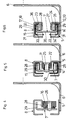
- the pull-out rail 8 is below the drawer bottom 19 next to the Drawer side wall 4 arranged.
- Each pull-out rail 8 has a front provided upwardly projecting pin 10, with which they in a hole in a Front piece 2 of the drawer protrudes and has a hook 9 at the back, which in one horizontal hole is anchored in the rear wall 3 of the drawer.
- the drawer cover 1 Before the Front piece 2 is the drawer cover 1, which so far over the Drawer bottom 19 protrudes downward that the pull-out guide set in front of the drawer cover 1 is covered.
- the mounting rail 5 is fastened to the body side wall 20 by means of two brackets 6.
- the brackets 6 are screwed to the body side wall 20, for example.
- the middle rail 7 is provided in its center with a control roller 11 which between horizontal catwalks 27, 28 of the mounting rail 5 and the pull-out rail 8 expire.
- the control roller 11 is in the embodiment of FIGS. 3 to 6 by a Rivet-carried axle pin 25 held on the middle rail 7, but has opposite enough in the axle pin 25 so that the weight of the drawer always directly from the pull-out rail 8 via the control roller 11 to the Support rail 5 is transmitted without the axle pin 25 or the center rail 7 strain.
- a support roller 16 is arranged on an axle bolt 26 and on which the pull-out rail 8 is supported.
- the Center rail 7 is in the embodiment of FIGS. 3 to 6 as a superscript U-profile executed with an upper and lower catwalk 29 and a vertical Connecting bridge 30.
- the catwalks 29 each project between a narrower one horizontal walkway 27, 28 and a wider horizontal walkway 31, 32 of Support rail 5 and the pull-out rail 8.
- Carriages 14, 15 are arranged between the rails 5, 7, 8, in which Store rollers 12, 13, 17, 18 and side compensation rollers 21, 22, 23, 24.
- the rollers 12, 13, 17, 18 are all within the U-profile of the Middle rail 7.
- the rollers 12, 13 run between the lower catwalk 29 Center rail 7 and the horizontal catwalk 27 from the mounting rail 5, and the Rollers 17, 18 between the narrower horizontal web 28 of the pull-out rail 8 and the upper runway 29 of the middle rail 7.
- the support rail 5 and the pull-out rail 8 have vertical edge webs 33, 34. Between the vertical edge webs 33, 34 and the vertical central web 30 of the Center rail 7 run off the compensating rollers 21, 22. Between the central web 30 the Center rail 7 and vertical edge webs 35, 36 of the mounting rail 5 and Pull-out rail 8 are the compensating rollers 23, 24.
- rollers 17 and 13 are located immediately above and below the control roller 11.
- rollers 12, 13, 17, 18 are just like the lateral compensating rollers 21, 22, 23, 24 formed in the embodiment of a roller.
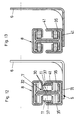
- the central rail 7 has a double T profile on.
- the middle rail 7 can be made in one piece, for example by Extrusions are made.
- the Center rail 7 formed by two steel rails 7 'with a U-profile, with their Connect connecting bars 30 back to back.
- the middle rail 7 is in the embodiment according to FIGS. 7 to 14 in its middle two control rollers 11 provided between the horizontal catwalks 27, 28 of the Support rail 5 and the pull-out rail 8 run off.
- the control rollers 11 are from Ironing 37 held on the middle rail 7. This way the weight of the Drawer always directly from the pull-out rail 8 via the control roller 11 transfer the mounting rail 5 without loading the center rail 7.
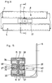
- On every side the central rail 7 is a control roller 11. For heavier However, as shown in Fig. 16, it is possible to drawers on either side of the drawers Center rail 7 several control rollers 11 in tandem in a row to arrange.
- the arms 38 of the bracket 37 have hooks 39 which are in notches 40 in the engage the corresponding arm 38 of the opposite bracket 37.
- the poor 38 protrude through holes in the connecting webs 30 of the steel rails 3, the together form the middle rail 7.
- the support rollers 16 are in turn at the front end of the center rail 7 arranged, which are mounted on a common axle pin 26 and on which the pull-out rail 8 supports.
- the middle rail 7 again has upper and lower Catwalks 29 open.
- the catwalks 29 each project between a narrower one horizontal walkway 27, 28 and a wider horizontal walkway 31, 32 of Support rail 5 and the pull-out rail 8.
- the carriages 14, 15 are arranged, in which Store rollers 12, 13, 17, 18 and side compensation rollers 21, 22, 23, 24.
- rollers 12, 13, 17, 18 and the compensating rollers 23, 24 are all located within the profile of the middle rail 7.
- the side webs 35 are the Support rail 5 provided with folded areas 41, i.e. the side webs are 35 bent over in such a way that two web sections are joined together in the regions 41 issue.
- These folded regions 41 extend from the narrower ones Horizontal webs 27 of the mounting rail 5 upwards in the direction of the pull-out rail 8.
- the folded areas 41 result in a considerable reinforcement of the mounting rail 5 reached.
- At the front end of the mounting rail 5 are the side webs 35 and Cut out catwalks 27 to leave enough space for the support rollers 16.
Landscapes
- Drawers Of Furniture (AREA)
Abstract
Description
Claims (11)
- Ausziehführungsgarnitur für Schubladen mit einer korpusseitigen Tragschiene (5), einer ladenseitigen Ausziehschiene (8) und einer zwischen diesen beiden Schienen (5, 8) angeordneten Mittelschiene (7) an jeder Seite der Schublade, wobei in Laufwagen (14, 15) gelagerte Laufrollen (12, 13, 17, 18) vorgesehen sind, die die Last der Schublade zwischen den Schienen (5, 7, 8) übertragen, und an der Mittelschiene (7) bezogen auf ihre Länge, in deren Mitte mindestens eine Steuerrolle (11) gelagert ist, die an einem Steg der Tragschiene (5) und an einem Steg der Ausziehschiene (8) abläuft, wobei die Mittelschiene (7) mit hochgestelltem U- oder Doppel-T-Profil ausgeführt ist, das von oberen und unteren horizontalen Laufstegen (29) und einem vertikalen Verbindungssteg (30) gebildet wird und sämtliche der in den Laufwagen (14, 15) gelagerten Laufrollen (12, 13, 17, 18) zwischen den Laufstegen (29) der Mittelschiene (7) angeordnet sind und die Tragschiene (5) und die Ausziehschiene (8) seitliche Randbereiche mit U-Profil aufweisen, die von breiteren Verbindungsstegen (31, 32) und schmäleren Laufstegen (27, 28) gebildet werden, dadurch gekennzeichnet, daß am vorderen Ende der Mittelschiene (7) mindestens eine Stützrolle (16) für die Ausziehschiene (8) lagert und daß die Steuerrolle (11) zwischen den schmäleren Laufstegen (27, 28), der Tragschiene (5) und der Ausziehschiene (8) abläuft.
- Ausziehführungsgarnitur nach Anspruch 1, dadurch gekennzeichnet, daß die Laufstege (29) der Mittelschiene (7) jeweils zwischen zwei horizontale Stege der Tragschiene (5) und der Ausziehschiene (8) ragen.
- Ausziehführungsgarnitur nach Anspruch 1 oder Anspruch 2, dadurch gekennzeichnet, daß das Doppel-T-Profil der Mittelschiene (7) von zwei Schienen (7') mit U-Profilen gebildet wird, die mit ihren Verbindungsstegen (30) Rücken an Rücken aneinander anliegen.
- Ausziehführungsgarnitur nach einem der Ansprüche 1 bis 3, dadurch gekennzeichnet, daß an jeder Seite der Mittelschiene (7) mindestens eine Steuerrolle (11) gelagert ist.
- Ausziehführungsgarnitur nach einem der Ansprüche 1 bis 4, dadurch gekennzeichnet, daß sich an mindestens einer Seite der Mittelschiene (7) mindestens zwei Steuerrollen (11) in Tandemanordnung befinden.
- Ausziehführungsgarnitur nach einem der Ansprüche 1 bis 5, dadurch gekennzeichnet, daß an der Mittelschiene (7) zwei Stützrollen (16) auf einem gemeinsamen Achsbolzen (26) lagern.
- Ausziehführungsgarnitur nach einem der Ansprüche 1 bis 6, dadurch gekennzeichnet, daß die Steuerrollen (11) achslos gelagert sind und an der Mittelschiene (7) von in Draufsicht U-förmigen Bügeln (37) gehalten werden, deren Arme (38) durch den Verbindungssteg der Mittelschiene (7) ragen und wobei die Arme (38) der einander gegenüberliegenden Bügel (37) ineinander einhaken.
- Ausziehführungsgarnitur nach einem der Ansprüche 1 bis 7, dadurch gekennzeichnet, daß die Durchmesser der Stützrollen (16) größer sind als die Durchmesser der Steuerrollen (11).
- Ausziehführungsgarnitur nach einem der Ansprüche 1 bis 8, dadurch gekennzeichnet, daß mindestens die Seitenstege (35) der Tragschiene (5) einen gefalzten Bereich (41) aufweisen.
- Ausziehführungsgarnitur nach einem der Ansprüche 1 bis 9, dadurch gekennzeichnet, daß an jeder Seite der Mittelschiene (7) mindestens zwei Steuerrollen (11) hintereinander angeordnet sind.
- Ausziehführungsgarnitur nach einem der Ansprüche 1 bis 10, dadurch gekennzeichnet, daß die Steuerrolle (11) stirnseitig aus dem Profil der Mittelschiene (7) herausragt.
Priority Applications (1)
| Application Number | Priority Date | Filing Date | Title |
|---|---|---|---|
| AT97116842T ATE245920T1 (de) | 1996-10-07 | 1997-09-27 | Ausziehführungsgarnitur für schubladen |
Applications Claiming Priority (6)
| Application Number | Priority Date | Filing Date | Title |
|---|---|---|---|
| AT176496 | 1996-10-07 | ||
| AT0176496A AT407001B (de) | 1996-10-07 | 1996-10-07 | Ausziehführungsgarnitur für schubladen |
| AT62796 | 1996-10-25 | ||
| AT1764/96 | 1996-10-25 | ||
| AT0062796U AT1644U1 (de) | 1996-10-25 | 1996-10-25 | Ausziehführungsgarnitur für schubladen |
| AT627/96 | 1996-10-25 |
Publications (3)
| Publication Number | Publication Date |
|---|---|
| EP0834270A2 true EP0834270A2 (de) | 1998-04-08 |
| EP0834270A3 EP0834270A3 (de) | 2001-10-24 |
| EP0834270B1 EP0834270B1 (de) | 2003-07-30 |
Family
ID=25593402
Family Applications (1)
| Application Number | Title | Priority Date | Filing Date |
|---|---|---|---|
| EP97116842A Expired - Lifetime EP0834270B1 (de) | 1996-10-07 | 1997-09-27 | Ausziehführungsgarnitur für Schubladen |
Country Status (8)
| Country | Link |
|---|---|
| US (1) | US5882100A (de) |
| EP (1) | EP0834270B1 (de) |
| JP (1) | JP3348193B2 (de) |
| KR (1) | KR100318449B1 (de) |
| CN (1) | CN1124098C (de) |
| BR (1) | BR9706722A (de) |
| DE (1) | DE59710502D1 (de) |
| ES (1) | ES2201235T3 (de) |
Cited By (6)
| Publication number | Priority date | Publication date | Assignee | Title |
|---|---|---|---|---|
| WO2008099253A3 (en) * | 2007-02-12 | 2008-12-04 | Inter Ikea Sys Bv | Pull-out mechanism for a drawer |
| US7748801B2 (en) | 2007-03-14 | 2010-07-06 | Alfit Ag | Telescopic guide for drawers and similar furniture components extendable from a body of furniture |
| DE102010036433A1 (de) * | 2010-07-15 | 2012-01-19 | Paul Hettich Gmbh & Co. Kg | Ausziehführung für Möbel und Verfahren zur Herstellung einer Auszugsführung |
| AT512934A4 (de) * | 2012-11-12 | 2013-12-15 | Blum Gmbh Julius | Schubladenausziehführung |
| DE102004002823B4 (de) * | 2004-01-12 | 2016-05-04 | Grass Gmbh | Ausziehführung für Schubladen |
| WO2018048937A1 (en) | 2016-09-07 | 2018-03-15 | Atea Pharmaceuticals, Inc. | 2'-substituted-n6-substituted purine nucleotides for rna virus treatment |
Families Citing this family (56)
| Publication number | Priority date | Publication date | Assignee | Title |
|---|---|---|---|---|
| MY131063A (en) * | 2002-05-17 | 2007-07-31 | Harn Marketing Sdn Bhd | Guide rails pull-out drawer/equipment |
| US7320508B2 (en) * | 2003-05-13 | 2008-01-22 | Grass America Inc. | Roller and stopper mechanism for a drawer slide system |
| US7171099B2 (en) | 2003-07-31 | 2007-01-30 | Adc Telecommunications, Inc. | Slide arrangement for cable drawer |
| DE102004002822A1 (de) * | 2004-01-12 | 2005-08-04 | Alfit Ag | Ausziehführung für Schubladen |
| US20090243451A1 (en) * | 2004-01-12 | 2009-10-01 | Christian Prentner | Drawer pull-out guide |
| US20050229360A1 (en) * | 2004-04-15 | 2005-10-20 | Lowe Mark J | Hinge |
| US20060273705A1 (en) * | 2005-06-07 | 2006-12-07 | Kuo-Liang Yeh | Drawer slide assembly |
| US7533946B2 (en) * | 2005-08-25 | 2009-05-19 | Knape & Vogt Manufacturing Company | Closing device for drawers |
| WO2008038472A1 (fr) * | 2006-09-28 | 2008-04-03 | Thk Co., Ltd. | Module à glissières |
| US7409137B2 (en) * | 2006-10-04 | 2008-08-05 | Adc Telecommunications, Inc. | Slide arrangement for cable drawer |
| US20080092783A1 (en) * | 2006-10-23 | 2008-04-24 | Chen Simon S | Roller extension slide |
| US7866772B1 (en) * | 2008-01-24 | 2011-01-11 | Gslide Corporation | Sliding rail coupling structure for hidden sliding track assembly |
| US8414094B2 (en) * | 2008-02-04 | 2013-04-09 | Accuride International, Inc. | Drawer system slide assemblies and closure mechanisms |
| TWI448655B (zh) * | 2008-02-29 | 2014-08-11 | Panasonic Corp | A track device and a refrigerator using the device |
| CN101606788B (zh) * | 2008-06-17 | 2011-09-07 | 李绍汉 | 抽屉导轨同步装置 |
| DE202008008121U1 (de) * | 2008-06-19 | 2009-10-29 | Paul Hettich Gmbh & Co. Kg | Auszugsführung für Möbelauszugsteile |
| US8511769B2 (en) * | 2010-12-17 | 2013-08-20 | Bsh Home Appliances Corporation | Home appliance with improved rack system |
| EP2526823B1 (de) * | 2011-05-24 | 2016-11-02 | Peka-Metall AG | Schrankelement mit einem Schrankauszug |
| EP2764389A4 (de) | 2011-10-07 | 2015-09-23 | Adc Telecommunications Inc | Verschiebbares faseroptisches verbindungsmodul mit kabelüberlängenverwaltung |
| US9002166B2 (en) | 2011-10-07 | 2015-04-07 | Adc Telecommunications, Inc. | Slidable fiber optic connection module with cable slack management |
| US9170391B2 (en) | 2011-10-07 | 2015-10-27 | Adc Telecommunications, Inc. | Slidable fiber optic connection module with cable slack management |
| US9075203B2 (en) | 2012-01-17 | 2015-07-07 | Adc Telecommunications, Inc. | Fiber optic adapter block |
| AT512754A1 (de) * | 2012-03-20 | 2013-10-15 | Blum Gmbh Julius | Möbelauszug |
| TWM454775U (zh) * | 2012-07-03 | 2013-06-11 | Nan Juen Int Co Ltd | 滑軌同步式連動裝置 |
| US10082636B2 (en) | 2012-09-21 | 2018-09-25 | Commscope Technologies Llc | Slidable fiber optic connection module with cable slack management |
| US9195021B2 (en) | 2012-09-21 | 2015-11-24 | Adc Telecommunications, Inc. | Slidable fiber optic connection module with cable slack management |
| CN105074525A (zh) | 2013-01-29 | 2015-11-18 | 泰科电子瑞侃有限公司 | 光纤分布系统 |
| US9128262B2 (en) | 2013-02-05 | 2015-09-08 | Adc Telecommunications, Inc. | Slidable telecommunications tray with cable slack management |
| EP2962148A4 (de) | 2013-02-27 | 2016-10-19 | Adc Telecommunications Inc | Verschiebbares glasfaser-verbindungsmodul mit kabelüberlängenverwaltung |
| US9398805B2 (en) * | 2013-02-28 | 2016-07-26 | Zodiac Seats Us Llc | Track roller food table slide |
| US9033437B2 (en) * | 2013-03-15 | 2015-05-19 | Whirlpool Corporation | Slide assembly for refrigerator storage drawer |
| CN105393151B (zh) | 2013-04-24 | 2018-09-18 | 泰科电子瑞侃有限公司 | 光导纤维分配系统 |
| DK2989496T3 (da) | 2013-04-24 | 2019-08-19 | CommScope Connectivity Belgium BVBA | Universel monteringsmekanisme til montering af et telekommunikationschassis til et telekommunikationsfikstur |
| US10247886B2 (en) | 2014-12-10 | 2019-04-02 | Commscope Technologies Llc | Fiber optic cable slack management module |
| US10261281B2 (en) | 2015-04-03 | 2019-04-16 | CommScope Connectivity Belgium BVBA | Telecommunications distribution elements |
| US11674345B2 (en) | 2016-04-19 | 2023-06-13 | Commscope, Inc. Of North Carolina | Door assembly for a telecommunications chassis with a combination hinge structure |
| WO2017184508A1 (en) | 2016-04-19 | 2017-10-26 | Commscope, Inc. Of North Carolina | Telecommunications chassis with slidable trays |
| AT518980B1 (de) * | 2016-10-28 | 2018-03-15 | Blum Gmbh Julius | Schubladenausziehführung |
| US11215767B2 (en) | 2017-06-07 | 2022-01-04 | Commscope Technologies Llc | Fiber optic adapter and cassette |
| AT520404A1 (de) * | 2017-08-30 | 2019-03-15 | Blum Gmbh Julius | Schubladenausziehführung |
| US11385429B2 (en) | 2017-10-18 | 2022-07-12 | Commscope Technologies Llc | Fiber optic connection cassette |
| DE102017128751A1 (de) * | 2017-12-04 | 2019-06-06 | Grass Gmbh | Schubelement-Führungssystem |
| EP3759535A4 (de) | 2018-02-28 | 2021-11-10 | CommScope Technologies LLC | Gehäuseanordnung für telekommunikationsausrüstung |
| US11256054B2 (en) | 2018-04-16 | 2022-02-22 | Commscope Technologies Llc | Adapter structure |
| US11635578B2 (en) | 2018-04-17 | 2023-04-25 | CommScope Connectivity Belgium BVBA | Telecommunications distribution elements |
| WO2020043911A1 (en) | 2018-08-31 | 2020-03-05 | CommScope Connectivity Belgium BVBA | Frame assemblies for optical fiber distribution elements |
| EP3844972B1 (de) | 2018-08-31 | 2022-08-03 | CommScope Connectivity Belgium BVBA | Rahmenanordnungen für glasfaserverteilungselemente |
| PL3844973T3 (pl) | 2018-08-31 | 2025-03-03 | CommScope Connectivity Belgium BVBA | Zespoły ram do elementów dystrybucji światłowodów |
| EP3844546A1 (de) | 2018-08-31 | 2021-07-07 | CommScope Connectivity Belgium BVBA | Rahmenanordnungen für optische faserverteilungselemente |
| EP3844547A1 (de) | 2018-08-31 | 2021-07-07 | CommScope Connectivity Belgium BVBA | Rahmenanordnungen für glasfaserverteilungselemente |
| EP3871028B1 (de) | 2018-10-23 | 2025-06-18 | CommScope Connectivity Belgium BVBA | Rahmenanordnungen für optische faserverteilungselemente |
| WO2020152347A1 (en) | 2019-01-25 | 2020-07-30 | CommScope Connectivity Belgium BVBA | Frame assemblies for optical fiber distribution elements |
| DE102019124732A1 (de) * | 2019-09-13 | 2021-03-18 | Paul Hettich Gmbh & Co. Kg | Auszugsführung |
| EP4094107B1 (de) | 2020-01-22 | 2025-06-18 | CommScope Connectivity Belgium BVBA | Kabelabschlusseinheiten für optische faserverteilungselemente |
| WO2021148552A1 (en) | 2020-01-24 | 2021-07-29 | CommScope Connectivity Belgium BVBA | Telecommunications distribution elements |
| US12468106B2 (en) | 2020-02-07 | 2025-11-11 | CommScope Connectivity Belgium BVBA | Telecommunications module arrangements |
Family Cites Families (16)
| Publication number | Priority date | Publication date | Assignee | Title |
|---|---|---|---|---|
| US2162318A (en) * | 1937-01-12 | 1939-06-13 | Globe Wernicke Co | Drawer suspension |
| FR1127644A (fr) * | 1955-06-10 | 1956-12-20 | Const De Vanves H Dumenil Atel | Support coulissant |
| US3912341A (en) * | 1973-10-23 | 1975-10-14 | Hardware Designers Inc | Progressive drawer slide |
| DE2613775A1 (de) * | 1976-03-31 | 1977-10-13 | Martin Greeb | Teleskopschiene zur fuehrung von schubkaesten |
| AT372830B (de) * | 1981-11-02 | 1983-11-25 | Fulterer Gmbh | Schubladenauszugeinrichtung in teleskopbauart |
| AT387897B (de) * | 1984-12-20 | 1989-03-28 | Blum Gmbh Julius | Unterflur-fuehrungsschienengarnitur |
| GB8529940D0 (en) * | 1985-12-04 | 1986-01-15 | Jackson P A S | Ball slide system |
| JPH0763423B2 (ja) * | 1991-11-08 | 1995-07-12 | スガツネ工業株式会社 | スライドレール装置 |
| AT401712B (de) * | 1992-08-19 | 1996-11-25 | Blum Gmbh Julius | Differentialauszug für schubladen |
| DE9307088U1 (de) * | 1993-05-12 | 1993-07-01 | Paul Hettich GmbH & Co, 4983 Kirchlengern | Auszugführung für einen Schubkasten |
| AT407473B (de) * | 1994-07-07 | 2001-03-26 | Alfit Ag | Vollauszug für schubladen |
| AT243U1 (de) * | 1994-08-30 | 1995-06-26 | Julius Blum Ges M B H Julius B | Ausziehfuehrungsgarnitur fuer schubladen |
| JPH08150035A (ja) * | 1994-11-28 | 1996-06-11 | Takigen Mfg Co Ltd | アルミスライドレール |
| AT404222B (de) * | 1995-01-04 | 1998-09-25 | Blum Gmbh Julius | Ausziehführungsgarnitur für schubladen |
| JP3614201B2 (ja) * | 1995-03-16 | 2005-01-26 | 共栄工業株式会社 | 抽斗のダブルサスペンション装置 |
| JPH08252129A (ja) * | 1995-03-17 | 1996-10-01 | Kyoei Kogyo Kk | 引出用サスペンション装置 |
-
1997
- 1997-09-27 EP EP97116842A patent/EP0834270B1/de not_active Expired - Lifetime
- 1997-09-27 ES ES97116842T patent/ES2201235T3/es not_active Expired - Lifetime
- 1997-09-27 DE DE59710502T patent/DE59710502D1/de not_active Expired - Lifetime
- 1997-10-03 JP JP27133797A patent/JP3348193B2/ja not_active Expired - Fee Related
- 1997-10-06 CN CN97120043A patent/CN1124098C/zh not_active Expired - Fee Related
- 1997-10-07 BR BR9706722-9A patent/BR9706722A/pt not_active IP Right Cessation
- 1997-10-07 US US08/946,656 patent/US5882100A/en not_active Expired - Lifetime
- 1997-10-07 KR KR1019970051460A patent/KR100318449B1/ko not_active Expired - Fee Related
Cited By (12)
| Publication number | Priority date | Publication date | Assignee | Title |
|---|---|---|---|---|
| DE102004002823B4 (de) * | 2004-01-12 | 2016-05-04 | Grass Gmbh | Ausziehführung für Schubladen |
| WO2008099253A3 (en) * | 2007-02-12 | 2008-12-04 | Inter Ikea Sys Bv | Pull-out mechanism for a drawer |
| US8888202B2 (en) | 2007-02-12 | 2014-11-18 | Inter Ikea Systems B.V. | Pull-out mechanism for a drawer |
| US7748801B2 (en) | 2007-03-14 | 2010-07-06 | Alfit Ag | Telescopic guide for drawers and similar furniture components extendable from a body of furniture |
| US8474926B2 (en) | 2007-03-14 | 2013-07-02 | Alfit Ag | Telescopic guide for drawers and similar furniture components extendable from a body of furniture |
| DE102010036433A1 (de) * | 2010-07-15 | 2012-01-19 | Paul Hettich Gmbh & Co. Kg | Ausziehführung für Möbel und Verfahren zur Herstellung einer Auszugsführung |
| AT512934A4 (de) * | 2012-11-12 | 2013-12-15 | Blum Gmbh Julius | Schubladenausziehführung |
| AT512934B1 (de) * | 2012-11-12 | 2013-12-15 | Blum Gmbh Julius | Schubladenausziehführung |
| WO2014071425A1 (de) | 2012-11-12 | 2014-05-15 | Julius Blum Gmbh | Schubladenausziehführung |
| US9204722B2 (en) | 2012-11-12 | 2015-12-08 | Julius Blum Gmbh | Drawer pull-out guide |
| WO2018048937A1 (en) | 2016-09-07 | 2018-03-15 | Atea Pharmaceuticals, Inc. | 2'-substituted-n6-substituted purine nucleotides for rna virus treatment |
| EP3865136A1 (de) | 2016-09-07 | 2021-08-18 | ATEA Pharmaceuticals, Inc. | 2'-substituierte-n6-substituierte purinnukleotide zur behandlung des corona-virus |
Also Published As
| Publication number | Publication date |
|---|---|
| KR100318449B1 (ko) | 2002-04-22 |
| KR19980032621A (ko) | 1998-07-25 |
| BR9706722A (pt) | 2001-05-22 |
| CN1124098C (zh) | 2003-10-15 |
| JPH10211045A (ja) | 1998-08-11 |
| JP3348193B2 (ja) | 2002-11-20 |
| CN1192345A (zh) | 1998-09-09 |
| EP0834270A3 (de) | 2001-10-24 |
| EP0834270B1 (de) | 2003-07-30 |
| ES2201235T3 (es) | 2004-03-16 |
| US5882100A (en) | 1999-03-16 |
| DE59710502D1 (de) | 2003-09-04 |
Similar Documents
| Publication | Publication Date | Title |
|---|---|---|
| EP0834270A2 (de) | Ausziehführungsgarnitur für Schubladen | |
| AT408090B (de) | Ausziehvorrichtung zur aufnahme von schwerlasten, insbesondere für ein lastfahrzeug, wie ein einsatzfahrzeug | |
| DE3623743C2 (de) | ||
| DE2149510A1 (de) | Kranausleger | |
| EP0826326A2 (de) | Regal für Lager- oder Kommissionierzwecke | |
| DE29906227U1 (de) | Teleskop-Schrankauszug | |
| DE9005619U1 (de) | Ausziehführungsgarnitur für Schubladen o.dgl. | |
| EP0021386B1 (de) | Längenverstellbarer Baukörper | |
| EP0720824B1 (de) | Ausziehführungsgarnitur für Schubladen | |
| EP0790022A2 (de) | Unterflur-Ausziehführung für Schubladen etc. | |
| DE8018747U1 (de) | Auszugführung für einen Schubkasten | |
| DE3906682A1 (de) | Seil-umlenkvorrichtung | |
| EP0761133A1 (de) | Ausziehführungsgarnitur für Schubladen | |
| DE3033360A1 (de) | Schubkastenfuehrung fuer ausziehbare moebelteile | |
| DE3106103A1 (de) | Traeger fuer regalboeden, insbesondere fuer den ladenbau | |
| DE69203075T2 (de) | Aufbau einer Heckklappe als Hebebühne. | |
| DE10110722A1 (de) | Eckversteifung oder -verstärkung von Schiebeflügeln | |
| EP3955727B1 (de) | Landwirtschaftliche maschine | |
| EP1350444B1 (de) | Unterbodenausziehführung für ausziehbare Möbel | |
| AT1644U1 (de) | Ausziehführungsgarnitur für schubladen | |
| AT407001B (de) | Ausziehführungsgarnitur für schubladen | |
| EP0698545A1 (de) | Doppelstockwagen | |
| EP1798108B1 (de) | Verriegelbare Auszugsschiebeführung | |
| EP3293096B1 (de) | Traggerüst für einen planenaufbau eines nutzfahrzeugs und runge für ein solches traggerüst | |
| DE3941488C1 (en) | Roller guide for furniture drawer - has drawer rail with U=shaped profile to grip guide rail on furniture |
Legal Events
| Date | Code | Title | Description |
|---|---|---|---|
| PUAI | Public reference made under article 153(3) epc to a published international application that has entered the european phase |
Free format text: ORIGINAL CODE: 0009012 |
|
| AK | Designated contracting states |
Kind code of ref document: A2 Designated state(s): AT BE CH DE DK ES FI FR GB GR IE IT LI LU MC NL PT SE Kind code of ref document: A2 Designated state(s): AT DE ES FR GB IT |
|
| AX | Request for extension of the european patent |
Free format text: AL;LT;LV;RO;SI |
|
| PUAL | Search report despatched |
Free format text: ORIGINAL CODE: 0009013 |
|
| AK | Designated contracting states |
Kind code of ref document: A3 Designated state(s): AT BE CH DE DK ES FI FR GB GR IE IT LI LU MC NL PT SE |
|
| AX | Request for extension of the european patent |
Free format text: AL;LT;LV;RO;SI |
|
| 17P | Request for examination filed |
Effective date: 20020125 |
|
| AKX | Designation fees paid |
Free format text: AT DE ES FR GB IT |
|
| 17Q | First examination report despatched |
Effective date: 20020607 |
|
| GRAH | Despatch of communication of intention to grant a patent |
Free format text: ORIGINAL CODE: EPIDOS IGRA |
|
| GRAH | Despatch of communication of intention to grant a patent |
Free format text: ORIGINAL CODE: EPIDOS IGRA |
|
| GRAA | (expected) grant |
Free format text: ORIGINAL CODE: 0009210 |
|
| AK | Designated contracting states |
Designated state(s): AT DE ES FR GB IT |
|
| PG25 | Lapsed in a contracting state [announced via postgrant information from national office to epo] |
Ref country code: GB Free format text: LAPSE BECAUSE OF FAILURE TO SUBMIT A TRANSLATION OF THE DESCRIPTION OR TO PAY THE FEE WITHIN THE PRESCRIBED TIME-LIMIT Effective date: 20030730 Ref country code: FR Free format text: LAPSE BECAUSE OF NON-PAYMENT OF DUE FEES Effective date: 20030730 |
|
| REG | Reference to a national code |
Ref country code: GB Ref legal event code: FG4D Free format text: NOT ENGLISH |
|
| REF | Corresponds to: |
Ref document number: 59710502 Country of ref document: DE Date of ref document: 20030904 Kind code of ref document: P |
|
| GBV | Gb: ep patent (uk) treated as always having been void in accordance with gb section 77(7)/1977 [no translation filed] |
Effective date: 20030730 |
|
| REG | Reference to a national code |
Ref country code: ES Ref legal event code: FG2A Ref document number: 2201235 Country of ref document: ES Kind code of ref document: T3 |
|
| PLBE | No opposition filed within time limit |
Free format text: ORIGINAL CODE: 0009261 |
|
| STAA | Information on the status of an ep patent application or granted ep patent |
Free format text: STATUS: NO OPPOSITION FILED WITHIN TIME LIMIT |
|
| 26N | No opposition filed |
Effective date: 20040504 |
|
| EN | Fr: translation not filed | ||
| PGFP | Annual fee paid to national office [announced via postgrant information from national office to epo] |
Ref country code: AT Payment date: 20140926 Year of fee payment: 18 |
|
| REG | Reference to a national code |
Ref country code: AT Ref legal event code: MM01 Ref document number: 245920 Country of ref document: AT Kind code of ref document: T Effective date: 20150927 |
|
| PG25 | Lapsed in a contracting state [announced via postgrant information from national office to epo] |
Ref country code: AT Free format text: LAPSE BECAUSE OF NON-PAYMENT OF DUE FEES Effective date: 20150927 |
|
| REG | Reference to a national code |
Ref country code: DE Ref legal event code: R079 Ref document number: 59710502 Country of ref document: DE Free format text: PREVIOUS MAIN CLASS: A47B0088100000 Ipc: A47B0088493000 |
|
| PGFP | Annual fee paid to national office [announced via postgrant information from national office to epo] |
Ref country code: DE Payment date: 20161130 Year of fee payment: 20 |
|
| PGFP | Annual fee paid to national office [announced via postgrant information from national office to epo] |
Ref country code: ES Payment date: 20161024 Year of fee payment: 20 Ref country code: IT Payment date: 20160922 Year of fee payment: 20 |
|
| REG | Reference to a national code |
Ref country code: DE Ref legal event code: R071 Ref document number: 59710502 Country of ref document: DE |
|
| REG | Reference to a national code |
Ref country code: ES Ref legal event code: FD2A Effective date: 20180508 |
|
| PG25 | Lapsed in a contracting state [announced via postgrant information from national office to epo] |
Ref country code: ES Free format text: LAPSE BECAUSE OF EXPIRATION OF PROTECTION Effective date: 20170928 |