EP0833074B1 - Magnetic spring having damping characteristics and vibration mechanism having same - Google Patents
Magnetic spring having damping characteristics and vibration mechanism having same Download PDFInfo
- Publication number
- EP0833074B1 EP0833074B1 EP97914630A EP97914630A EP0833074B1 EP 0833074 B1 EP0833074 B1 EP 0833074B1 EP 97914630 A EP97914630 A EP 97914630A EP 97914630 A EP97914630 A EP 97914630A EP 0833074 B1 EP0833074 B1 EP 0833074B1
- Authority
- EP
- European Patent Office
- Prior art keywords
- magnetic
- vibration
- permanent magnets
- magnets
- spring
- Prior art date
- Legal status (The legal status is an assumption and is not a legal conclusion. Google has not performed a legal analysis and makes no representation as to the accuracy of the status listed.)
- Expired - Lifetime
Links
Images


Classifications
-
- F—MECHANICAL ENGINEERING; LIGHTING; HEATING; WEAPONS; BLASTING
- F16—ENGINEERING ELEMENTS AND UNITS; GENERAL MEASURES FOR PRODUCING AND MAINTAINING EFFECTIVE FUNCTIONING OF MACHINES OR INSTALLATIONS; THERMAL INSULATION IN GENERAL
- F16F—SPRINGS; SHOCK-ABSORBERS; MEANS FOR DAMPING VIBRATION
- F16F6/00—Magnetic springs; Fluid magnetic springs, i.e. magnetic spring combined with a fluid
- F16F6/005—Magnetic springs; Fluid magnetic springs, i.e. magnetic spring combined with a fluid using permanent magnets only
-
- F—MECHANICAL ENGINEERING; LIGHTING; HEATING; WEAPONS; BLASTING
- F16—ENGINEERING ELEMENTS AND UNITS; GENERAL MEASURES FOR PRODUCING AND MAINTAINING EFFECTIVE FUNCTIONING OF MACHINES OR INSTALLATIONS; THERMAL INSULATION IN GENERAL
- F16F—SPRINGS; SHOCK-ABSORBERS; MEANS FOR DAMPING VIBRATION
- F16F15/00—Suppression of vibrations in systems; Means or arrangements for avoiding or reducing out-of-balance forces, e.g. due to motion
- F16F15/02—Suppression of vibrations of non-rotating, e.g. reciprocating systems; Suppression of vibrations of rotating systems by use of members not moving with the rotating systems
- F16F15/03—Suppression of vibrations of non-rotating, e.g. reciprocating systems; Suppression of vibrations of rotating systems by use of members not moving with the rotating systems using magnetic or electromagnetic means
Definitions
- the present invention relates to a magnetic spring having a plurality of permanent magnets.
- vibration characteristics depend on the loaded mass and the input. It is considered that there is a correlation between the loaded mass and the curvature of load-deflection characteristics, and between the input and the hysteresis of load-deflection characteristics.
- the points core adjusting ride comfort are the road surface condition, the control stability, and the impedance (or the difference thereof) condition.
- the active control is needed. Annoying road driving or high-speed driving result in significant differences in a low frequency and high amplitude region. In the case where the damping force is low, the transmissibility of deflection will increase, and the resonance frequency will shift to the lower frequency region. In order to increase the damping force, it is necessary to increase the damping ratio of a damper, or decrease the spring constant. Therefore, conventional passive vibration models have a limit on its performance.
- suspension seats are described hereinafter.
- the suspension seats are the seats available mainly in off-road vehicles, such as earth-moving machines or recreational vehicles (RV), or long-distance travelling vehicles, such as trucks or busses, and equipped with a vibration isolator mechanism.
- the vibration isolator mechanism metal springs, an air suspension, air dampers or the like are used.
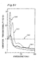
- the isolation of seat vibration has been improved within the frequency range from about 1.5 to 12 Hz, especially from 3 to 5Hz. Therefore, suspension seats have a resonance frequency in the range of 1 to 2.5Hz.
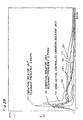
- Fig. 51 depicts the vibration characteristics of conventional suspension seats.
- (a) indicates a rigid seat
- an active suspension seat wherein an actuator mounted to the seat works to active-control vibrations to enhance the ride comfort.
- the vibration isolator mechanism employing the metal springs, air suspension, air dampers or the like cannot enhance the ride comfort or the feeling of use by decreasing a vibration frequency of 4-20Hz from among vibrations transmitted through the vehicle floor.
- the active suspension seat is heavy and expensive and is also required to always activate the actuator. If the actuator is turned off, vibrations are transmitted to a seat occupant through the actuator, thus losing the ride comfort.
- the damping force is too great, it may worsen the vibration isolation performance for the seat in the low and middle frequency region, i.e., at more than about 1.4 times of the resonance frequency.
- JP 07-217687 A discloses a magnetic spring comprising first and second permanent magnets spaced from each other with like magnetic poles opposed to each other, the maximum separation distance of the magnets being adjustable.
- the present invention has been developed to overcome the above-described disadvantages. It is accordingly an objective of the present invention to provide a magnetic spring having positive, 0- or negative damping characteristics by utilizing permanent magnets. Another objective of the present invention is to realize an inexpensive dynamic-characteristic control system or highly efficient engine of a simple construction by providing a stable nonlinear vibration mechanism or coefficient exciting vibration mechanism having the aforementioned magnetic spring and no physical damping structure.
- the magnetic spring according to the present invention comprises the features according to claim 1.
- the maximum repulsive force can be generated at the closest position of the at least two permanent magnets or the position having passed the closest position.
- a magnetic spring structure is made up of at least two spaced permanent magnets with the same magnetic poles opposed to each other, the two spaced permanent magnets are held in non-contact with each other. Accordingly, if the friction loss in the structure itself is small enough to be ignored, the static characteristics thereof are reversible, i.e., the output (return) is on the same line as the input (go) and is nonlinear. Furthermore, negative damping can be easily produced by changing the static magnetic field (the arrangement of the magnets) with a small amount of input utilizing the degree of freedom peculiar to the non-contact pair and the instability of the float control system.
- the present invention has been developed taking note of this fact.
- the geometric dimensions between the two permanent magnets are changed by a mechanism inside a kinetic system in which the permanent magnets are placed or by an external force.
- the change in geometric dimensions is converted into a repulsive force in the kinetic system to make the repulsive force from the balanced position of the two permanent magnets greater at the time of output than at the time of input.
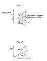
- Fig. 1 schematically depicts balanced positions of two permanent magnets 2 and 4 on the input side and on the output side
- Fig. 2 depicts the fundamental characteristics of the magnetic spring structure indicating a relationship between the load applied to one of the two permanent magnets and the deflection thereof from the balanced position.
- the static characteristics indicate negative damping characteristics, as shown in Fig. 2, and if is conceivable that the potential difference between the position x 1 and the position x 0 corresponds to the potential energy for oscillation.
- FIG. 3 A model of Fig. 1 was made and a relationship between the load and the deflection was measured by changing the time during which the load was applied. As a result, a graph shown in Fig. 3 was obtained and can be interpreted as meaning that when the two permanent magnets 2 and 4 approaches their closest position, a great repulsive force is produced, and that when the amount of deflection from the balanced position changes slightly, a friction loss is produced by a damper effect of the magnetic spring, thus creating a damping term.
- (a) is a curve obtained when a constant load was applied, and the time during which the load was being applied becomes shorter in the order of (a), (b) and (c).
- the static characteristics vary according to the manner in which the load is applied, and the longer is the time during which the load is applied, the greater the impulse is.
- the strength of magnetization does not depend upon the magnetic field. More specifically, because the internal magnetic moment is not easily influenced by the magnetic field, the strength of magnetization on a demagnetization curve hardly changes, and the value is kept almost as same as that of saturation magnetization. Accordingly, in the case of rare-earth magnets, the force can be calculated using a charge model assuming that the magnetic load is uniformly distributed on its surfaces.
- Fig. 4 depicts the way of thinking in which a magnet is defined as a set of smallest unit magnets. The relationship of forces acting among the unit magnets was calculated by classifying it into three.
- the forces can be obtained by integrating the above (-f x ) and (-f z ) with respect to the range of the magnet size.
- the above results of calculation are generally in agreement with the results of actual measurement.
- the force required for moving the point (a) to the point (b) in Fig. 2 is the x-axis load, while the output is represented by the z-axis load.
- the relationship of input ⁇ output caused by instability is statically clarified.
- Fig. 7 is a graph indicating the relationship between the x-axis load and the z-axis load when the distance between the magnets is kept as 3mm, and the condition of the magnets is changed from the completely slipped condition to the completely lapped one, and again to the completely slipped one.
- This graph is a characteristic curve indicating that the absolute value of the x-axis load is the same but the direction of output is reversed.
- the former receives a resistance, resulting in damping.
- the former is accelerated.
- Fig. 10 is a graph indicating a relationship between the load and the distance between the magnets when neodymium-based magnets are employed.
- the repulsive force increase in mass.
- the geometric dimensions mean the size determined by the distance between the opposing magnets, the opposing area, the magnetic flux density, the strength of the magnetic field or the like. If the magnet material is the same, the strangth of magnetization (Br) is constant and, hence, the repulsive force of the magnets can be changed by changing the geometric dimension.
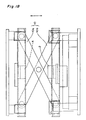
- Fig. 11 depicts a specific magnetic spring model according to the present invention wherein the geometric dimensions are changed by changing the opposing area of magnets 2 and 4.
- a base 6 and a top plate 8 extending parallel to each other are connected by two X-links 10 each having two links 10a and 10b.
- One end of the link 10a and that of the link 10b are pivotally mounted on the base 6 and the top plate 8, respectively, while the other end of the link 10a and that of the link 10b are pivotally mounted on an upper slider 12 slidably mounted on the top plate 8 and a lower slider 14 slidably mounted on the base 6, respectively.
- the base 6 has a linear way 16 fixedly mounted thereon on which a magnet platform 18 having the permanent magnet 2 placed thereon is slidably mounted, while the permanent magnet 4 is fixedly mounted on the top plate 8.
- the base 6 also has a support 20 secured thereto on which a generally central portion of an L-shaped lever 22 comprised of a first arm 22a and a second arm 22b is pivotally mounted.
- the first arm 22a has one end pivotally mounted on the magnet platform 18, while the second arm 22b has a balance weight 24 mounted thereon.
- the position where the maximum repulsive force is produced can be regulated by moving the balance weight 24 along the second arm 22b according to the input. Moreover, the timing or the opposing area can be regulated by interlocking the permanent magnet 4 with the upper slider 12.
- Fig. 12 depicts another model having two permanent magnets 2 and 4 fixedly mounted on the base 6 and the top plate 8, respectively, and also having two additional permanent magnets 26 and 28 utilized to change the geometric dimensions by changing the gap (distance) between them.
- the permanent magnet 28 is fixed to the top plate 8 with the S-pole thereof directed downwards in contrast with the permanent magnet 4, while the permanent magnet 26 is fixed to one end of a rocking arm 30 with the S-pole thereof directed upwards in contrast with the permanent magnet 2.
- a central portion of the rocking arm 30 is pivotally mounted on the support 20, and a balance weight 24 is mounted on the rocking arm 30 on the side opposite to the permanent magnet 26.
- the magnetic attraction acts therebetween as a balancing spring.
- the permanent magnet 26 is moved upwards by the inertia force of the balance weight 24 against the magnetic attraction of the permanent magnet 2.
- the gap or distance between the permanent magnets 26 and 28 gradually changes, and the maximum repulsive force is produced at the closest position thereof or the position having passed such a position.
- the base 6 is then moved downwards by the repulsive force.
- the magnetic spring of Fig. 12 exhibits negative damping characteristics as shown in Fig. 3.
- the position where the maximum repulsive force is produced can be regulated by moving the balance weight 24 along the rocking arm 30 according to the input.
- Fig. 13 depicts a further model wherein the geometric dimensions of the two opposing permanent magnets 2 and 4 are changed by utilizing a rotary lever.
- the permanent magnet 2 is fixed to the base 6, while the permanent magnet 4 opposing the permanent magnet 2 is fixed to a mount 34 which is slidably mounted on a frame 32 extending upwards from the base 6.
- a link 36 is pivotally connected at one end thereof to the mount 34 and at the other end thereof to a first support 38 fixed to one side of the lower slider 14.
- a second support 40 is fixed to the other side of the lower slider 14, and a lever 42 is pivotally connected at one end thereof to the second support 40 and has a pin 44 mounted on the other end thereof.
- the pin 44 is loosely inserted into an elongated opening 36a defined in an intermediate portion of the link 36 and is also mounted on a lower end of an arm 46 pivotally mounted on the top plate 8.
- Fig. 14 depicts a magnetic spring wherein the geometric dimensions are changed by utilizing a pole conversion of the permanent magnets.
- the permanent magnet 2 is rotatably mounted on the base 6 and has a small-diameter pulley 48 fixed thereto.
- This pulley 48 is connected via a belt 52 to a large-diameter pulley 50 rotatably mounted on the base 6.
- the pulley 50 is connected at the center thereof to one end of a link 54, the other end of which is connected to a lever 56 on which a balance weight 24 is mounted.
- the position of a lower end of the balance weight 24 is restrained by a spring member 60 mounted on the top plate 8 via a bracket 58.
- Fig. 15 depicts a magnetic spring wherein the geometric dimensions are changed by changing the magnetic flux density of the permanent magnets.
- a plurality of shielding plates 66 are pivotally connected at both ends thereof to a first support plate 62 fixed to the base 6 and to a second support plate 64 spaced a predetermined distance from the first support plate 62 and extending parallel thereto.
- An L-shaped lever 70 is pivotally connected at an intermediate portion thereof to one end of the second support plate 64 via an arm 68.
- the L-shaped lever 70 has one end pivotally connected to a support 72 fixed to the base 6 and the other end on which the balance weight 24 is mounted.
- the second support plate 64 is moved in a direction opposite to the arrow to open the upper space of the permanent magnet 2. Accordingly, the repulsive force of the permanent magnets 2 and 4 is increased, and the base 6 is moved downwards away from the top plate 8. While the base 6 is being moved up and down, the magnetic spring of Fig. 15 exhibits negative damping characteristics as shown in Fig. 3.
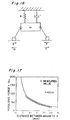
- an input F is the force produced by a change in geometric dimensions such as, for example, the area conversion of the permanent magnets.
- Fig. 17 indicates a relationship between the distance (x) of the opposing magnet surfaces and the repulsive force (f) when two permanent magnets (Nd-Fe-B system) having an opposing area of 50 ⁇ 25mm 2 and a thickness of 10mm are opposed so as to repulse each other.
- the characteristics of the magnetic spring were made into a function, and an equation of motion was formulated. Because the repulsive force acting between the magnets is given by k/x, as described above, the characteristic equation is given by: In Fig, 16, the total mass including the mass of the upper permanent magnet 4 and a load applied to the magnet 4, the spring constant, the damping coefficient, and a harmonic excitation inputted to the mass m are represented by m, k, r, and F(t), respectively.
- the relationship between the natural frequency and the spring constant is the reverse of the metal spring.
- the curvature of the optimum load-deflection characteristics can be calculated by adjusting the setting position of the operation point and the magnetic circuit, it may be possible to keep the resonant point constant.
- the equation (3) has a damping term of -bx 2 in the term of the second degree.
- a constant repulsive force ((b/2)x 0 2 ) is continuously applied to a periodic external force to attenuate it. That means that, by adjusting the locus of motion of the permanent magnets, damping effect is available without equipping with a damper mechanism.
- the apparatus of Fig. 18 has two opposing permanent magnets 2 and 4, the distance of which is changed via X-links 10 without any area conversion.
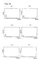
- Figs. 19 and 20 the axis of abscissa indicates the frequency (Hz), while the axis of ordinate indicates the vibration transmissibility (G/G).
- Fig. 19 (a), (b), (c), (d), (e), and (f) are graphs obtained when the same load of 30kg was applied with the use of magnets of 50 ⁇ 50 ⁇ 10mm, 50 ⁇ 50 ⁇ 15mm, 50 ⁇ 50 ⁇ 20mm, 75 ⁇ 75 ⁇ 15mm, 75 ⁇ 75 ⁇ 20mm, and 75 ⁇ 75 ⁇ 25mm, respectively.
- different loads of 53kg and 80kg were applied with the use of the same magnet of 50 ⁇ 50 ⁇ 20mm.
- Figs. 19 and 20 indicate the nonlinear characteristics of the magnetic spring and have revealed that when the load is the same, as the opposing area of the magnets increases, the distance between the magnets increases, the resonant point is shifted to a lower frequency region, and the vibration transmissibility becomes smaller.
- the magnetic spring behaves in the way opposite to the metal spring or the air spring.
- the magnet size is the same, even if the load is changed, the resonant point does not change.
- the vibration transmissibility is reduced. In short, the vibration transmissibility at the resonant point depends on the magnitude of the load.
- Fig. 21 is a graph employed as a comparative example indicating the dynamic characteristics of a conventional automotive seat and reveals that the vibration transmissibility is high as a whole, and both the resonant point and the vibration transmissibility vary with a change of load.
- the resonant frequency is given by: ⁇ o ⁇ m n - k'
- a self-excited vibration system can be replaced with a spring-mass system having negative damping characteristics, and energy of vibration is introduced thereinto from outside during vibration.
- the actual vibration however, loses energy because air resistance or various resistances act on the mass point.
- the vibration system having the magnetic spring of the present invention includes an energy conversion system inducing continuous oscillation or diverging vibration. Adding a positive damping term to the above characteristic equation results in the following equation.
- coefficient exciting vibration In the case where the magnitude of at least one of the mass, damping coefficient, and spring constant in a vibration system changes with time, the vibration caused thereby is referred to as coefficient exciting vibration.
- equations (7), (8), and (9) indicates the coefficient exciting vibration in which an exciting source itself vibrates and generates vibration by converting non-vibrating energy within the system to vibratory excitation.
- the amplitude can be attenuated by maximizing the opposing area of the permanent magnets 2 and 4 when the permanent magnet 4 is positioned at its lower end.
- This feature is applicable to a magnetic brake, dynamic damper or the like.
- the repulsive force can be increased by maximizing the opposing area when the permanent magnet 4 is moved from its lower end towards it upper end. This feature is applicable to a generator, amplifier or the like.
- the coefficient exciting vibration system can reduce variations in amplitude by moving the exciting frequency even if the natural frequency varies according to variations in load.
- the resonant frequency can be reduced by making the exciting frequency variable and causing the resonant frequency to manually or automatically follow it.
- Fig. 23 depicts the results of the experiments.
- the vibration isolator device employing the magnetic spring structure of the present invention together with the pads was recognized as an extremely effective one because of the fact that it could lower the resonant frequency to 3Hz which is less than half the resonant frequency of the vibration isolator device employing only the pads. Furthermore, the vibration transmissibility at the resonant point could be reduced to about 1/3 by active-controlling the vibration isolator device.
- Fig. 24 depicts a magnetic levitation unit. Upon investigation of the dynamic characteristics thereof, the results shown in Fig. 25 could be obtained.
- the magnetic levitation unit of Fig. 24 comprises a base 74, a seat 78 swingably mounted on the base 74 via a plurality of swingable levers 76, two permanent magnet 80 and 82 spaced a predetermined distance from each other and fixedly mounted on the upper surface of the base 74, and a permanent magnet 84 fixedly mounted on the lower surface of the seat 78 so that the same magnetic poles may be opposed to each other with respect to the permanent magnet 80 and 82.
- Each of the permanent magnets has a size of 75 ⁇ 75 ⁇ 25mm
- Fig. 25 is a graph obtained when different loads of 53kg, 75kg, and 80kg were applied to this magnetic levitation unit. As shown therein, not only could the difference in vibration transmissibility caused by variations of the load be limited to be small, but also the resonant point could be made substantially constant.
- the seat comfort was investigated using automotive seats, suspension seats A, suspension seats B, and the magnetic levitation unit of the present invention.
- the results were as shown in Fig. 26.
- the load applied to the magnetic levitation unit was 53kg and permanent magnets of 75 ⁇ 75 ⁇ 25mm were used.
- "fixed" indicates the condition in which the seat was merely fixed on a suspension, and urethane, gel, or styrene is the material of cushion placed on the unit.
- the values obtained in the automotive seats are 0.2-0.3 (all-urethane seats) and 0.3-0.5 (metal spring seats), and those obtained in the suspension seats to which weight adjustments were conducted are 0.5-0.7.
- the seat comfort of the magnetic levitation unit of the present invention is better than that of other seats, and the evaluation values of seat comfort thereof are 0.75-1.60 with respect to a load of 53kg.
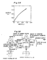
- Fig. 27 indicates evaluation values of seat comfort of the magnetic levitation unit when the load applied thereto was changed. As can be seen from this figure, evaluations values of seat comfort more than 0.7 could be obtained with respect to any load, and this fact means that the magnetic levitation unit of the present invention is superior in seat comfort.
- Fig. 28 depicts the dynamic characteristics of an automotive seat, suspension seat A, suspension seat B, and the magnetic levitation unit of the present invention.
- (a) indicates the automotive seat
- the resonant point of the magnetic levitation unit exists between 2-3Hz and the vibration transmissibility in low and high frequency regions is small. It was also confirmed that semi-active control thereof could not only further lower the resonant point but also reduce the vibration transmissibility in a wide frequency region.
- Collisional vibration can be utilized in the nonlinear vibration system or coefficient exciting vibration system of the present invention.
- Collision as well as friction, is a typical nonlinear phenomenon in mechanical systems and causes something suddenly impeding motion such as, for example, deformation resistance of an object. Accordingly, the object having caused the collision is rapidly decelerated, resulting in generation of a very large acceleration.
- the magnetic spring also causes the same (quasi-) phenomenon as the collision.
- the contact area When an object having certain kinetic energy collides against something, the contact area is deformed so that the kinetic energy may be released as plastic deformation work, friction work by the contact surface, a wave motion into the inside of the object, or acoustic energy to the outside. The remainder of the kinetic energy is converted into elastic energy which is in turn converted into kinetic energy.
- the magnetic spring is featured by non-contact, no large loss is caused.
- the output is on the same line as the input and is nonlinear, and negative damping is likely caused.
- the magnetic levitation unit causes no end-stop impact, it is accelerated and self-excited by a repulsive force of + ⁇ , and exhibits vibration characteristics having no bad influence on human beings, though the vibration is low-damping one because of non-contact.
- metal springs are incorporated into the magnetic levitation unit and if the acceleration exceeds damping, it induces a complete elastic collision by the action of hard springs and causes self-excitation to prevent the second resonance. The amount of energy lost can be compensated for by a conversion of potential energy in the magnetic field.
- elastic support of a stopper which causes an end-stop impact can be utilized for vibration isolation and energy conversion, thereby compensating for shortage of the repulsive force of the magnetic spring.
- Fig. 29 is a model having an elastically supported stopper wherein the spring constant k of an elastic support member can absorb a predetermined acceleration or amplitude and is made variable. The resonant point can be adjusted by appropriately adjusting the spring constant k.
- Fig. 30 shows experimental values of input and output of a sliding-type principle model provided with magnets having an opposing area of 50 ⁇ 25mm 2 and a thickness of 10mm, wherein the friction loss was reduced as small as possible.
- the loaded mass was 3.135kg.
- Fig. 31 shows experimental values of input and output of a rotating-type principle model provided with magnets having an opposing area of 50 ⁇ 25mm 2 and a thickness of 10mm, wherein the area conversion is achieved with the center of gravity of one magnet as the center of rotation.
- Fig. 32 shows experimental values of input and output of the same rotating-type principle model in terms of work.
- Fig. 33 shows the points of a principle model of input and output. Because it is a non-contact system, it is possible to utilize acceleration and produce the greater energy apparently.
- the principle of virtual work is applied to the repulsive force acting between magnets, and the amount of variation of accumulated magnetic energy caused by shifting of the magnets is equal to the amount of job caused by shifting of the magnets.
- the manner in which the magnetic energy is extracted will be the point of a power-redoubling actuator.
- This amplifier can give the same effects as an amplifying transistor by input of electrical energy, and is characterized in that it effectively converts the stored magnetic energy to mechanical energy for subsequent utilization thereof. That is, it produces apparently the greater output (i.e. work) with a small input.
- ⁇ W m (h) indicates the amount of reduction of the accumulated magnetic energy.
- ⁇ W m (h) B 2 S ⁇ h/(2 ⁇ 0 )
- Fig. 35 indicates a change in repulsive force wherein magnets having an opposing area of 50 ⁇ 25mm 2 and a thickness of 10mm were used.
- Fig. 38 illustrates a rotating-type principle model
- Fig. 39 does a sliding-type principle model
- a lower permanent magnet 2 is rotatably mounted on a base 90, while an upper permanent magnet 4 is vertically slidably mounted on a slider 92. Accordingly, the two opposing permanent magnets 2 and 4 exhibit load-deflection characteristics as shown in Fig. 35 by changing the distance therebetween or the opposing area thereof.
- a lower permanent magnet 2 is horizontally slidably mounted on a base 90, while an upper permanent magnet 4 is vertically slidably mounted on a slider 92. Accordingly, the two opposing permanent magnets 2 and 4 exhibit input-output work characteristics as shown in Fig. 36 by changing the distance therebetween or the opposing area thereof.
- the magnetic spring model of Fig. 11 the amount of gap and the opposing area are variables. For example, if a change in the amount of gap is followed by an appropriate change in the opposing area of the two permanent magnets 2 and 4 caused by the balance weight 24, the magnetic spring can have an appropriate spring constant at an arbitrary resonant point.
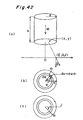
- Fig. 42 (a) indicates the coordinates of a columnar magnet and the metal conductor, (b) the circular cylindrical coordinates of the columnar magnet, and (c) the current density within the metal conductor.
- H z ( ⁇ , 0, z) H z L ( ⁇ , 0, z)+H z u ( ⁇ , 0, z)
- V
- the magnetic flux ⁇ (R, z) is determined as follows.
- the interaction energy of the magnet and the conductor is described.
- the current energy increased within the conductor i.e., the magnetic energy density u m is given by:
- F z (R) exerted on the whole current I(R) of a radius of R is given by: where z 1 and z 2 represent the distance from the lower surface of the magnet to the upper surface of the conductor and that to the lower surface of the conductor, respectively.
- ⁇ (R, z) represents the magnetic flux within the area surrounded by a radius of R within the conductor
- z 1 and z 2 represent the coordinates at the upper and lower surfaces of the conductor, respectively
- Fig. 43 depicts an embodiment applied to a vibration isolator device for suspension seats, wherein (a) shows the entire vibration isolator device, (b) is a side view of the vibration isolator device of (a), particularly showing a vertical damping structure, and (c) shows a horizontal vibration isolator unit swingably mounted on an upper portion of the vibration isolator device of (a).
- 2, 4, 94, and 96 denote permanent magnets
- 98 denotes a copper plate employed as a conductor.
- the vertical spring properties are obtained by a repulsive system comprised of the permanent magnets 2 and 4 and supported by parallel links 100 and 100.
- the vertical and horizontal damping structures in which damping is caused by electromagnetic induction are removable from each other.
- the damping force by electromagnetic induction can be changed by changing the thickness of the copper plate 98.
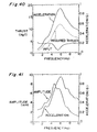
- Fig. 44 is a graph showing the comparison of vibration characteristics in the presence or absence of horizontal damping effect.
- the vibration transmissibility in a low frequency region is restrained to some extent by electromagnetic induction.
- the magnets can be regarded as being positioned within a demagnetic field and, hence, there may be a worry about causing the demagnetization during use.
- a dummy-magnetic-leakage structure in which different poles are alternately arranged can reduce the demagnetic field.
- Fig. 45 depicts a magnet arrangement of single pole, (b) that of two poles, (c) that of three poles, and (d) that of four poles.
- (e) is a figure as viewed from the direction of an arrow in the magnet arrangement (d) of four poles.
- the opposing area (75 ⁇ 75mm 2 ), volume 75 ⁇ 75 ⁇ 25mm 3 ) and Br-value (11.7KG) are the same, the Permeance coefficient differs as follows.
- Fig. 46 is a graph showing a relationship between the distance of the magnets and the repulsive force in the magnet arrangements of (a) to (d). As can be seen from this graph, when the opposing magnets approach each other, the repulsive force increases with the number of magnetic poles because a leakage magnetic field is created between the magnetic poles equivalent to magnetic walls, as described above.
- k around the balanced point is between 10-30N/mm. Therefore, when the loaded mass increases, the conventional automotive seats are apt to cause end-stop. In contrast, when the loaded mass decreases, the resonant frequency shifts to resonate internal organs or vertebral column, or the vibration transmissibility increases. For this reason, urethane foam having a damping function is used in a pad layer, while a soft spring-rich structure is obtained by the use of metal springs. Furthermore, a shock absorber is used to increase the damping function. In the automotive seats, the vibration isolating characteristics, the damping characteristics, the body pressure, and the posture stability are balanced using such various functional elements.
- the load-deflection characteristics providing a smooth change in natural frequency can be designed using the magnetic spring characteristics exhibiting the behavior opposite to metal springs or air springs.
- the vibration transmissibility was found ideal, because it was kept lower than 1.0 G/G at 2-3.5 Hz and lower than 0.4 G/G at 3.5-50 Hz, as shown in Fig. 50.
- an amplifier capable of producing a great output with a small input can be realized by incorporating the relationship of input and output of the negative damping characteristics into a power-doubling mechanism.
- active controllers employing this amplifier have the following good characteristics.
- the geometric dimensions between at least two opposing permanent magnets are changed by an external force on the input side and on the output side, and converted into a repulsive force within a kinetic system in which the permanent magnets are placed so that the repulsive force from a balanced position of the permanent magnets on the output side may be made greater than the repulsive force on the input side.
- the magnetic field as the field of potential can be effectively utilized, making it possible to realize an inexpensive magnetic brake, dynamic damper, dynamo, amplifier or the like.
- the nonlinear vibration system or coefficient exciting vibration system according to the present invention is of the structure for converting energy into damping; continuous or diverging vibration by making use of a magnetic spring having positive, 0-, or negative damping characteristics. Accordingly, by incorporating it into a vibration isolator device for automotive seats or beds for ambulance cars, it is possible to reduce the vibration transmissibility in a high frequency region, absorb the weight difference, or reduce vibration energy in a low frequency region for the reduction of the resonant point or the like.
Landscapes
- Engineering & Computer Science (AREA)
- General Engineering & Computer Science (AREA)
- Physics & Mathematics (AREA)
- Mechanical Engineering (AREA)
- Electromagnetism (AREA)
- Acoustics & Sound (AREA)
- Aviation & Aerospace Engineering (AREA)
- Vibration Prevention Devices (AREA)
Applications Claiming Priority (4)
| Application Number | Priority Date | Filing Date | Title |
|---|---|---|---|
| JP8512596 | 1996-04-08 | ||
| JP85125/96 | 1996-04-08 | ||
| JP8512596 | 1996-04-08 | ||
| PCT/JP1997/001196 WO1997038242A1 (fr) | 1996-04-08 | 1997-04-08 | Ressort magnetique dote de caracteristiques d'amortissement et mecanisme vibratoire equipe de ce type de ressort |
Publications (3)
| Publication Number | Publication Date |
|---|---|
| EP0833074A1 EP0833074A1 (en) | 1998-04-01 |
| EP0833074A4 EP0833074A4 (en) | 2000-06-14 |
| EP0833074B1 true EP0833074B1 (en) | 2004-06-23 |
Family
ID=13849930
Family Applications (1)
| Application Number | Title | Priority Date | Filing Date |
|---|---|---|---|
| EP97914630A Expired - Lifetime EP0833074B1 (en) | 1996-04-08 | 1997-04-08 | Magnetic spring having damping characteristics and vibration mechanism having same |
Country Status (8)
| Country | Link |
|---|---|
| US (1) | US6035980A (ko) |
| EP (1) | EP0833074B1 (ko) |
| KR (1) | KR100266432B1 (ko) |
| CN (1) | CN1077966C (ko) |
| AU (1) | AU2179297A (ko) |
| DE (1) | DE69729615T2 (ko) |
| TW (1) | TW333591B (ko) |
| WO (1) | WO1997038242A1 (ko) |
Families Citing this family (29)
| Publication number | Priority date | Publication date | Assignee | Title |
|---|---|---|---|---|
| JP3725272B2 (ja) * | 1996-12-27 | 2005-12-07 | 株式会社デルタツーリング | 振動発生機構 |
| KR100281474B1 (ko) * | 1997-05-16 | 2001-02-01 | 후지타 히토시 | 자기스프링을구비한에너지출력기구 |
| NL1007127C2 (nl) * | 1997-09-26 | 1999-03-29 | Univ Delft Tech | Draagsysteem. |
| US6166465A (en) * | 1998-04-30 | 2000-12-26 | Delta Tooling Co., Ltd. | Vibration generating mechanism using repulsive forces of permanent magnets |
| JP3115864B2 (ja) * | 1998-10-21 | 2000-12-11 | 株式会社デルタツーリング | 救急車用除振架台 |
| FR2792554B1 (fr) * | 1999-04-22 | 2001-06-29 | Vibrachoc Sa | Dispositif resonant, tel que batteur ou generateur d'efforts |
| JP2000337434A (ja) | 1999-05-25 | 2000-12-05 | Delta Tooling Co Ltd | 振動機構 |
| JP2001349374A (ja) * | 2000-06-02 | 2001-12-21 | Delta Tooling Co Ltd | 磁気バネ構造及び該磁気バネ構造を用いた除振機構 |
| JP2002021922A (ja) * | 2000-07-11 | 2002-01-23 | Delta Tooling Co Ltd | 磁気回路を利用した除振機構 |
| JP4931305B2 (ja) * | 2000-10-30 | 2012-05-16 | 株式会社デルタツーリング | マグネットユニット |
| JP2003148598A (ja) * | 2001-11-08 | 2003-05-21 | Honda Motor Co Ltd | 回転軸内の油通路構造 |
| US20040012168A1 (en) * | 2002-07-19 | 2004-01-22 | Martinrea International Inc. | Suspension system with magnetic resiliency |
| KR100540194B1 (ko) | 2003-09-23 | 2006-01-10 | 한국전자통신연구원 | 차량을 이용한 알에프아이디 태그 설치 시스템 및 그 방법 |
| GB0408366D0 (en) * | 2004-04-15 | 2004-05-19 | Kab Seating Ltd | Seat suspension system |
| ATE494489T1 (de) * | 2006-07-05 | 2011-01-15 | Skf Ab | Feder, federanordnung und dämpfer sowie fahrzeug |
| US10046677B2 (en) | 2013-04-23 | 2018-08-14 | Clearmotion Acquisition I Llc | Seat system for a vehicle |
| US9339911B2 (en) * | 2013-11-19 | 2016-05-17 | Eriksson Teknik Ab | Method for automatic sharpening of a blade |
| FI125110B (en) | 2013-11-27 | 2015-06-15 | Teknologian Tutkimuskeskus Vtt Oy | hanging Organizer |
| DE102014200035B4 (de) | 2014-01-07 | 2024-02-08 | Volkswagen Aktiengesellschaft | Vorrichtung und Verfahren zum Halten eines Objekts in einem Fahrzeug |
| CN103775550B (zh) * | 2014-02-14 | 2015-09-23 | 华中科技大学 | 单自由度磁力隔振装置 |
| US9643467B2 (en) * | 2014-11-10 | 2017-05-09 | Bose Corporation | Variable tracking active suspension system |
| FR3032686B1 (fr) * | 2015-02-18 | 2017-03-10 | Messier Bugatti Dowty | Atterrisseur d'aeronef comprenant une tige lineaire telescopique |
| WO2016197154A1 (en) | 2015-06-04 | 2016-12-08 | Milsco Manufacturing Company | Modular forward and rearward seat position adjustment system, with integral vibration isolation system |
| CN109590947A (zh) * | 2018-11-15 | 2019-04-09 | 彩虹(合肥)光伏有限公司 | 一种振动器间隙调整用工具 |
| CN112474607B (zh) * | 2020-11-05 | 2022-04-12 | 厦门理工学院 | 一种激光清洗机的防震机构 |
| CN114877884B (zh) * | 2022-04-22 | 2022-11-25 | 之江实验室 | 一种无人机惯性导航组件隔振系统结构优化设计方法 |
| CN114962514B (zh) * | 2022-04-29 | 2023-05-12 | 北京交通大学 | 单球磁性液体碰撞阻尼减振器 |
| CN114889506B (zh) * | 2022-05-20 | 2023-03-31 | 安徽工程大学 | 一种特种车辆上专用的永磁减震椅及其减震效果验证方法 |
| CN116147943B (zh) * | 2023-04-23 | 2023-07-11 | 成都大学 | 一种评价高速磁悬浮列车系统运行稳定性的方法 |
Family Cites Families (43)
| Publication number | Priority date | Publication date | Assignee | Title |
|---|---|---|---|---|
| US3088062A (en) * | 1956-02-10 | 1963-04-30 | Albert A Hudimac | Electromechanical vibratory force suppressor and indicator |
| DE1805789B2 (de) * | 1968-10-29 | 1972-01-27 | Breitbach, Elmar, Dipl Ing , 3400 Gottingen | Nichtlineares federsystem unter verwendung von permanent magneten |
| NL6817259A (ko) * | 1968-12-03 | 1970-06-05 | ||
| US3609425A (en) * | 1970-04-07 | 1971-09-28 | Francis R Sheridan | Reciprocating magnet motor |
| US3770290A (en) * | 1972-01-24 | 1973-11-06 | F Bottalico | Vehicle shock absorber |
| US3842753A (en) * | 1973-08-03 | 1974-10-22 | Rohr Industries Inc | Suspension dampening for a surface support vehicle by magnetic means |
| US3952979A (en) * | 1975-02-19 | 1976-04-27 | Hughes Aircraft Company | Isolator |
| US3941402A (en) * | 1975-03-03 | 1976-03-02 | Yankowski Anthony P | Electromagnetic shock absorber |
| US4189699A (en) * | 1977-04-08 | 1980-02-19 | Mfe Corporation | Limited-rotation motor with integral displacement transducer |
| GB2006958B (en) * | 1977-07-14 | 1982-04-07 | Gearing & Watson Electronics L | Electro-mechanical devices |
| US4300067A (en) * | 1980-03-17 | 1981-11-10 | Schumann Albert A | Permanent magnet motion conversion device |
| JPS57169212A (en) * | 1981-04-13 | 1982-10-18 | Kokka Kogyo Kk | Vibration suppressing device |
| DE3117377A1 (de) * | 1981-05-02 | 1982-12-30 | AMD-Vertriebsgesellschaft für Antriebstechnik mbH, 5800 Hagen | Verfahren und vorrichtung zum umwandeln einer antriebsbewegung |
| DE3136320C2 (de) * | 1981-09-12 | 1983-10-20 | Deutsche Forschungs- und Versuchsanstalt für Luft- und Raumfahrt e.V., 5000 Köln | Verfahren und Vorrichtung zur Unterdrückung des Außenlast-Tragflügel-Flatterns von Flugzeugen |
| JPS5889077A (ja) * | 1981-11-21 | 1983-05-27 | Toshiaki Ashizawa | 磁石で動く動力機 |
| DE3274009D1 (en) * | 1982-08-13 | 1986-12-04 | Ibm | High-performance vibration filter |
| US4498038A (en) * | 1983-02-15 | 1985-02-05 | Malueg Richard M | Stabilization system for soft-mounted platform |
| DE3410473C2 (de) * | 1983-04-11 | 1986-02-06 | Deutsche Forschungs- und Versuchsanstalt für Luft- und Raumfahrt e.V., 5000 Köln | Federungssystem für ein Kraftfahrzeug |
| JPH0244583Y2 (ko) * | 1985-03-12 | 1990-11-27 | ||
| JPS61215826A (ja) * | 1985-03-19 | 1986-09-25 | Sanai Kogyo Kk | 防振テ−ブル水平保持装置 |
| JPS61231871A (ja) * | 1985-04-03 | 1986-10-16 | Kazuo Takagi | 磁石によるモ−タ− |
| US4913482A (en) * | 1985-09-30 | 1990-04-03 | Mitsubishi Denki Kabushiki Kaisha | Seat suspension system for automotive vehicle or the like |
| DE3601182A1 (de) * | 1986-01-17 | 1987-07-23 | Peter Pohl Gmbh Dipl Ing | Ruetteltisch |
| US5017819A (en) * | 1986-11-04 | 1991-05-21 | North American Philips Corporation | Linear magnetic spring and spring/motor combination |
| US4710656A (en) * | 1986-12-03 | 1987-12-01 | Studer Philip A | Spring neutralized magnetic vibration isolator |
| JPS63149446A (ja) * | 1986-12-11 | 1988-06-22 | Bridgestone Corp | 防振装置 |
| SE8701138D0 (sv) * | 1987-03-19 | 1987-03-19 | Asea Ab | Elektriskt styrt fjederelement |
| GB2222915A (en) * | 1988-08-01 | 1990-03-21 | James Louis Noyes | Magnetic devices to assist movement of a component |
| US4950931A (en) * | 1989-01-17 | 1990-08-21 | Motorola, Inc. | Vibrator |
| IL89983A (en) * | 1989-04-17 | 1992-08-18 | Ricor Ltd Cryogenic & Vacuum S | Electromagnetic vibrating system |
| DE3935909A1 (de) * | 1989-11-01 | 1991-05-02 | Vnii Ochrany Truda I Techniki | Aufhaengung des sitzes von fahrzeugen |
| JPH0434246A (ja) * | 1990-05-29 | 1992-02-05 | Yoshiya Kikuchi | 永久磁石緩衝器 |
| JP3182158B2 (ja) * | 1991-02-25 | 2001-07-03 | キヤノン株式会社 | 露光装置用のステージ支持装置 |
| US5120030A (en) * | 1991-05-28 | 1992-06-09 | General Motors Corporation | Magnet assisted liftgate strut |
| CH683217A5 (it) * | 1991-07-03 | 1994-01-31 | Pier Andrea Rigazzi | Procedimento che utilizza l'azione di campi magnetici permanenti per muovere un sistema di corpi lungo una traiettoria muovendone un secondo di moto alternato. |
| US5231336A (en) * | 1992-01-03 | 1993-07-27 | Harman International Industries, Inc. | Actuator for active vibration control |
| US5584367A (en) * | 1993-04-14 | 1996-12-17 | Berdut; Elberto | Permanent magnet type automotive vehicle suspension |
| US5419528A (en) * | 1993-05-13 | 1995-05-30 | Mcdonnell Douglas Corporation | Vibration isolation mounting system |
| JP3036297B2 (ja) * | 1993-06-04 | 2000-04-24 | 神鋼電機株式会社 | 自動搬送車両 |
| JP3473979B2 (ja) * | 1994-02-02 | 2003-12-08 | 株式会社竹中工務店 | 床の制振装置 |
| GB9403580D0 (en) * | 1994-02-24 | 1994-04-13 | Coombs Timotha A | Bearing stiffener |
| GB2296068A (en) * | 1994-12-16 | 1996-06-19 | John Jeffries | Magnetic vibration isolator |
| US5587615A (en) * | 1994-12-22 | 1996-12-24 | Bolt Beranek And Newman Inc. | Electromagnetic force generator |
-
1997
- 1997-04-08 WO PCT/JP1997/001196 patent/WO1997038242A1/ja active IP Right Grant
- 1997-04-08 EP EP97914630A patent/EP0833074B1/en not_active Expired - Lifetime
- 1997-04-08 US US08/973,929 patent/US6035980A/en not_active Expired - Lifetime
- 1997-04-08 CN CN97190327A patent/CN1077966C/zh not_active Expired - Fee Related
- 1997-04-08 TW TW086104437A patent/TW333591B/zh not_active IP Right Cessation
- 1997-04-08 AU AU21792/97A patent/AU2179297A/en not_active Abandoned
- 1997-04-08 KR KR1019970709193A patent/KR100266432B1/ko not_active IP Right Cessation
- 1997-04-08 DE DE69729615T patent/DE69729615T2/de not_active Expired - Lifetime
Also Published As
| Publication number | Publication date |
|---|---|
| US6035980A (en) | 2000-03-14 |
| KR100266432B1 (ko) | 2000-10-02 |
| KR19990022751A (ko) | 1999-03-25 |
| AU2179297A (en) | 1997-10-29 |
| EP0833074A4 (en) | 2000-06-14 |
| DE69729615D1 (de) | 2004-07-29 |
| EP0833074A1 (en) | 1998-04-01 |
| DE69729615T2 (de) | 2005-06-23 |
| CN1188530A (zh) | 1998-07-22 |
| CN1077966C (zh) | 2002-01-16 |
| TW333591B (en) | 1998-06-11 |
| WO1997038242A1 (fr) | 1997-10-16 |
Similar Documents
| Publication | Publication Date | Title |
|---|---|---|
| EP0833074B1 (en) | Magnetic spring having damping characteristics and vibration mechanism having same | |
| Mizuno et al. | Vibration isolation system using negative stiffness | |
| US6585240B1 (en) | Vibration relief apparatus and magnetic damper mechanism therefor | |
| KR100331934B1 (ko) | 자기스프링을구비한진동기구 | |
| TWI286118B (en) | Balancing apparatus for elevator | |
| EP1055838B1 (en) | Vibration mechanism | |
| JP2000234649A (ja) | サスペンションユニット | |
| JP7060092B2 (ja) | 制振装置およびエレベーター装置 | |
| Ning et al. | A rotary variable admittance device and its application in vehicle seat suspension vibration control | |
| CN201566443U (zh) | 主动式质量减振器 | |
| CN109982892A (zh) | 悬架 | |
| Sultoni et al. | Modeling, prototyping and testing of regenerative electromagnetic shock absorber | |
| JP3747112B2 (ja) | 減衰特性を有する磁気バネ | |
| JP3924596B2 (ja) | 負の減衰特性を有する磁性バネ振動機構 | |
| JP3890383B2 (ja) | 減衰特性を有する磁性バネ | |
| JP3924597B2 (ja) | 負の減衰特性を有する磁性バネ振動機構 | |
| JP3903163B2 (ja) | 磁気浮上式サスペンションユニット | |
| Hoque et al. | A 3-DOF modular vibration isolation system using zero-power magnetic suspension with adjustable negative stiffness | |
| JPH03204369A (ja) | 車体曲げ振動防止装置 | |
| JPH1086725A (ja) | 磁気浮上式サスペンションユニット | |
| Li et al. | A tunable'negative'stiffness system for vibration control | |
| Fujita et al. | New vibration system using magneto-spring | |
| JPH1067267A (ja) | 磁気浮上式サスペンションユニット | |
| JP2008185184A (ja) | インホイールモータ用吸振機 | |
| Fujita et al. | Vibration characteristics of vertical suspension using magneto-spring |
Legal Events
| Date | Code | Title | Description |
|---|---|---|---|
| PUAI | Public reference made under article 153(3) epc to a published international application that has entered the european phase |
Free format text: ORIGINAL CODE: 0009012 |
|
| 17P | Request for examination filed |
Effective date: 19971217 |
|
| AK | Designated contracting states |
Kind code of ref document: A1 Designated state(s): DE ES FR GB IT SE |
|
| A4 | Supplementary search report drawn up and despatched |
Effective date: 20000502 |
|
| AK | Designated contracting states |
Kind code of ref document: A4 Designated state(s): DE ES FR GB IT SE |
|
| RIC1 | Information provided on ipc code assigned before grant |
Free format text: 7F 16F 15/03 A, 7B 60N 2/50 B, 7B 06B 1/04 B, 7F 16F 6/00 B |
|
| 17Q | First examination report despatched |
Effective date: 20020118 |
|
| GRAP | Despatch of communication of intention to grant a patent |
Free format text: ORIGINAL CODE: EPIDOSNIGR1 |
|
| GRAS | Grant fee paid |
Free format text: ORIGINAL CODE: EPIDOSNIGR3 |
|
| GRAA | (expected) grant |
Free format text: ORIGINAL CODE: 0009210 |
|
| AK | Designated contracting states |
Kind code of ref document: B1 Designated state(s): DE ES FR GB IT SE |
|
| PG25 | Lapsed in a contracting state [announced via postgrant information from national office to epo] |
Ref country code: IT Free format text: LAPSE BECAUSE OF FAILURE TO SUBMIT A TRANSLATION OF THE DESCRIPTION OR TO PAY THE FEE WITHIN THE PRESCRIBED TIME-LIMIT;WARNING: LAPSES OF ITALIAN PATENTS WITH EFFECTIVE DATE BEFORE 2007 MAY HAVE OCCURRED AT ANY TIME BEFORE 2007. THE CORRECT EFFECTIVE DATE MAY BE DIFFERENT FROM THE ONE RECORDED. Effective date: 20040623 Ref country code: FR Free format text: LAPSE BECAUSE OF FAILURE TO SUBMIT A TRANSLATION OF THE DESCRIPTION OR TO PAY THE FEE WITHIN THE PRESCRIBED TIME-LIMIT Effective date: 20040623 |
|
| REG | Reference to a national code |
Ref country code: GB Ref legal event code: FG4D |
|
| REF | Corresponds to: |
Ref document number: 69729615 Country of ref document: DE Date of ref document: 20040729 Kind code of ref document: P |
|
| PG25 | Lapsed in a contracting state [announced via postgrant information from national office to epo] |
Ref country code: SE Free format text: LAPSE BECAUSE OF FAILURE TO SUBMIT A TRANSLATION OF THE DESCRIPTION OR TO PAY THE FEE WITHIN THE PRESCRIBED TIME-LIMIT Effective date: 20040923 |
|
| PG25 | Lapsed in a contracting state [announced via postgrant information from national office to epo] |
Ref country code: ES Free format text: LAPSE BECAUSE OF FAILURE TO SUBMIT A TRANSLATION OF THE DESCRIPTION OR TO PAY THE FEE WITHIN THE PRESCRIBED TIME-LIMIT Effective date: 20041004 |
|
| PG25 | Lapsed in a contracting state [announced via postgrant information from national office to epo] |
Ref country code: GB Free format text: LAPSE BECAUSE OF NON-PAYMENT OF DUE FEES Effective date: 20050408 |
|
| PLBE | No opposition filed within time limit |
Free format text: ORIGINAL CODE: 0009261 |
|
| STAA | Information on the status of an ep patent application or granted ep patent |
Free format text: STATUS: NO OPPOSITION FILED WITHIN TIME LIMIT |
|
| 26N | No opposition filed |
Effective date: 20050324 |
|
| EN | Fr: translation not filed | ||
| GBPC | Gb: european patent ceased through non-payment of renewal fee |
Effective date: 20050408 |
|
| PGFP | Annual fee paid to national office [announced via postgrant information from national office to epo] |
Ref country code: DE Payment date: 20160419 Year of fee payment: 20 |
|
| REG | Reference to a national code |
Ref country code: DE Ref legal event code: R071 Ref document number: 69729615 Country of ref document: DE |