EP0829980A2 - Optisches Kommunikationssystem - Google Patents
Optisches Kommunikationssystem Download PDFInfo
- Publication number
- EP0829980A2 EP0829980A2 EP97115831A EP97115831A EP0829980A2 EP 0829980 A2 EP0829980 A2 EP 0829980A2 EP 97115831 A EP97115831 A EP 97115831A EP 97115831 A EP97115831 A EP 97115831A EP 0829980 A2 EP0829980 A2 EP 0829980A2
- Authority
- EP
- European Patent Office
- Prior art keywords
- optical
- station
- signal
- wavelength
- optical signal
- Prior art date
- Legal status (The legal status is an assumption and is not a legal conclusion. Google has not performed a legal analysis and makes no representation as to the accuracy of the status listed.)
- Withdrawn
Links
Images


Classifications
-
- H—ELECTRICITY
- H04—ELECTRIC COMMUNICATION TECHNIQUE
- H04J—MULTIPLEX COMMUNICATION
- H04J14/00—Optical multiplex systems
- H04J14/02—Wavelength-division multiplex systems
- H04J14/0221—Power control, e.g. to keep the total optical power constant
Definitions
- the present invention relates to an optical communications system applicable to long-distance communications such as underseas cable communications, etc.
- FIGs. 1A through 1F show the conventional optical add-drop system and the problem with the system.
- FIG. 1A is a block diagram showing the entire configuration of the optical add-drop system.
- the basic configuration in the optical add-drop system has a terminal station A as a transmitting station for transmitting an optical-wavelength multiplexed optical signal, a terminal station C as a receiving station for receiving a signal from the terminal station A, a branching unit 1100 for branching or combining an optical signal of a specific wavelength in the optical signals from the terminal station A, and a terminal station B for receiving the optical signal branched by the branching unit 1100, and transmitting new information with an optical signal having the same wavelength as the received optical signal.
- the branching unit 1100 is mounted underseas to transmit optical signals to, for example, the terminal stations A, B, and C provided in different nations.
- the distance between the terminal stations A and c is approximately 3,000km, and the branching unit 1100 is provided around the central point between these stations. Since the intensity of an optical signal is attenuated when the optical signal is transmitted for a long distance, the transmission lines between the terminal station A and the branching unit 1100, between the terminal station B and the branching unit 1100, and between the terminal station C and the branching unit 1100 have a plurality of optical amplifiers 1101, 1102, and 1103 respectively.
- each of the optical amplifiers 1101, 1102, and 1103 has an automatic output level control circuit (ALC circuit) to keep the output level of each of the optical amplifiers 1101, 1102, and 1103 constant so that the optical signal can be constantly amplified to a specific output level.
- ALC circuit automatic output level control circuit
- FIG. 1A shows the transmission line for one-way communications.
- the circuit is designed to establish two-way communications, that is, up-line and down-line communications.
- FIGs. 1B through 1F show an optical Signal and its problem in each transmission line.
- FIG. 1B shows the optical signal at point A in FIG. 1A.
- optical signals having four different wavelengths are wavelength-multiplexed and transmitted from the terminal station A.
- the mound under each optical signal is called an amplified spontaneous emission (ASE) noise. It is produced when a noise superposed to an optical signal is amplified with the optical signal by an optical amplifier.
- ASE amplified spontaneous emission
- the characteristics of the operations of the optical communications system depend on the S/N ratio of the optical signal to the ASE.
- the optical signal having a wavelength ⁇ 1 is branched and transmitted to the terminal station B, and an optical signal having the wavelength ⁇ 1 is transmitted from the terminal station B to the terminal station C.
- An optical signal having a wavelength other than wavelength ⁇ 1 in the signal (FIG. 1B) transmitted from the terminal station A is not branched by the branching unit 1100, but is transmitted as is to the terminal station C.
- the terminal station B receives the optical signal having wavelength ⁇ 1 and transmits an optical signal having the same wavelength ⁇ 1 .
- FIG. 1C shows the state at point B of the signal transmitted from the terminal station B and amplified by the optical amplifier 1102.
- the branching unit 1100 combines the optical signal having wavelength ⁇ 1 transmitted from the terminal station B with the light having wavelength ⁇ 2 through ⁇ 4 , and transmits the result to the terminal station C.
- FIG. 1D shows the state at point C of the optical signal from the terminal station B which is combined by the branching unit 1100 and amplified by an optical amplifier 1103.
- FIGs. 1C and 1D show the case where the power level of an optical signal is equal to that of each other when the optical signal from the terminal station B is combined with the optical signal from the terminal station A.
- an optical signal having any wavelength indicates the same S/N ratio to the ASE noise as shown in FIG. 1D.
- the two optical signals having different wavelengths are multiplexed, and an optical signal of a total of 0dBm power is input to the optical amplifier.
- the optical amplifier includes an automatic output level control circuit having a gain of 10dB and an optical output is limited to 10dBm.
- the state of the optical signal at the input terminal is -3dBm each for the power of the optical signals of two wavelengths, a total of 0dBm as shown in FIG. 2A.
- FIG. 2B shows the output when such optical signals are input to the optical amplifier. That is, the optical signal of each wavelength is amplified, and the power of each optical signal is +7dBm with a total power of the output light indicating +10dBm.
- the ASE noise is also amplified, and the S/N ratio to the ASE noise of each optical signal is 30dB. Therefore, the operation characteristic of the optical amplifier indicates the S/N ratio of 30dB.
- FIGs. 3A and 3B show the case where an input optical signal is multiplexed with an optical signal having a different power level.
- the characteristic of the optical amplifier is the same as that of the optical amplifier shown in FIGs. 2A and 2B.
- a total power of the optical signals having two different wavelengths is 0dBm with the power level of one optical signal indicating - 1.5dBm while the other optical signal indicating - 4.5dBm. There is 3dB difference between the power levels. If such optical signals are input, the output is obtained as shown in FIG. 3B.
- the higher power level of the optical signal between the two input signals is +8.5dBm while the lower power level of the optical signal is +5.5dBm because the optical signal having each wavelength is amplified such that the total power level of the output signals can be the above described value, that is, the output of the optical amplifier is fixed to +10dBm.
- the ASE noise is amplified and the S/N ratios are different between the wavelengths. That is, the S/N ratio of the wavelength indicating the higher power level is an acceptable value while the S/N ratio of the wavelength indicating the lower power level is relatively undesired. Since the operation characteristic of the optical amplifier is evaluated by the undesired S/N ratio, the performance of the optical amplifier is considered to be poor.
- optical add-drop system As described above by referring to FIG. 1A, a lot of optical amplifiers are inserted between the terminal station and the branching unit.
- the branching unit an independently generated optical signal from the terminal station A is combined with an optical signal from the terminal station B, and amplified by the optical amplifier.
- the optical signals of respective wavelengths from the terminal stations A and B may not match in power when they are combined because of the transmission distance and the difference in output.
- the power level of the optical signal may not be controlled Just as designed even if the system has been formed by carefully computing the output power and the attenuation of the optical signal in the designing step.
- the evaluation is made based on the lower S/N ratio indicating the transmission characteristic of the optical signal, thereby considering the system to be poor in performance.
- the present invention aims at providing an optical communications system capable of compensating the difference between the power level of the optical signal from the transmitting station and the optical signal from the branch station, and maintaining a high system performance.
- the optical communications system includes a transmitting station for transmitting a wavelength-multiplexed optical signal; a receiving station for receiving the optical signal; a branch station for receiving an optical signal having a specific wavelength in the wavelength-multiplexed optical signals and transmitting the optical signal on the specific wavelength; and a branching unit for branching the optical signal having the specific wavelength from the optical signal transmitted from the transmitting station, transmitting it to the branch station, and combining the optical signal transmitted from the branch station with the optical signal which has the wavelength other than the specific wavelength and has been transmitted from the branch station.
- the signals are combined with their power levels matching each other.
- the terminal station includes an optical transmission signal transmitting unit for generating an optical transmission signal modulated using the data to be transmitted; a dummy light generation unit for generating a dummy light different in wavelength from the optical transmission signal; a wavelength multiplexing unit for wavelength-multiplexing the dummy light and the optical transmission signal; and a level adjustment unit for adjusting the output level of the dummy light.
- the wavelength of the optical signal transmitted from the branch station is equal to that reflected by the fiber grating 11, it is also reflected by the fiber grating 13, input to the circulator 14 again, and transmitted to the receiving side.
- the excess light which has not been reflected by the fiber grating 13 is prevented by the isolator 12 from being propagated to the transmitting station.
- the S/N ratio is lowered when the signals are amplified by the optical amplifier if there is a difference between the power levels of the optical signals having respective wavelengths.
- an optical attenuator 15 is provided in the transmission line through which an optical signal is transmitted from the branch station. The optical attenuator 15 adjusts the power level of the optical signal from the branch station to make the optical signal transmitted from the transmitting station match in power level the optical signal transmitted from the branch station. Therefore, the system performance in the optical add-drop system can be maintained high.
- the connection between the optical fibers is fixed and the attenuation of an optical signal is also fixed. Therefore, the attenuation of the optical signal is adjusted by the axis-shifted splice only once when the system is designed.
- the optical attenuation can be maintained at a constant level for a long time, a reliable optical attenuator can be obtained in the case where the branching unit is provided underseas for use in underseas cable communications, and where the branching unit cannot be frequently maintained.
- the optical attenuation is normally adjusted by adjusting the amount of the shift of the optical axis of the optical fiber while confirming the optical attenuation when the optical fiber is spliced.
- an appropriate optical attenuation can be realized.
- the configuration of the optical attenuator is not limited to the above described axis-shifted splice, but can be optionally determined within the range normally anticipated by one of ordinary skill of the art.
- FIG. 6 shows the configuration of the second embodiment of the present invention.
- a branching unit 30 is designed in a way that the power level of the optical signal transmitted from the branch station is adjusted to match the power level of the optical signal transmitted from the transmitting station.
- FIG. 3 only the down-line from the transmitting station is indicated. (Actually, there can be an up-line.)
- the optical signal transmitted from the transmitting station is amplified by an optical amplifier 31, and branched by a coupler 32. Since the branching process in this example is performed to monitor the power level of the optical signal from the transmitting station, the power of the most optical signals is designed not to branched, but to pass straight. From the optical signals which pass straight, the optical signals having the wavelengths to be transmitted in a circulator 33 and a fiber grating 34 to the branch station are retrieved, and the retrieved optical signals are transmitted to the branch station. The optical signals having the other wavelengths pass further straight through the isolator 35, and a fiber grating 36 and a circulator 37 combine the optical signal from the branch station and transmit the result to the receiving station.
- the optical signal received by the photodiode 38 is transmitted after the optical signals having, for example, eight different wavelengths are transmitted from the transmitting station and multiplexed.
- the optical signals received by the photodiode 41 are transmitted from the branch station, and contain the optical signals having, for example, four wavelengths in the eight different wavelengths used in transmitting the optical signals from the transmitting station. Therefore, the optical signals received by the photodiode 38 contain 8 optical signals while the optical signals received by the photodiode 41 contain only four optical signals. If the power levels of these optical signals are directly compared, those received by the photodiode 38 are naturally higher.
- the power level of each wavelength of the optical signal transmitted from the branch station match the power level of each wavelength of the optical signal which has been transmitted from the transmitting station and has not been dropped (retrieved) to the branch station. Therefore, the power level of the 4-wave-multiplexed optical signal from the branch station is converted by the level converter 40 to match the power level of the 8-wave-multiplexed optical signal from the transmitting station. Then, the result is input to the comparator 39.
- the comparator 39 compares the power levels of the thus obtained electric signals and the comparison result is input to an operational amplifier 42.
- the comparison result is compared with the reference value (ref), and a control signal is issued to the optical amplifier 43 if there is a difference between the power level of the optical signal from the branch station and the power level of the optical signal from the transmitting station so that the power level of the optical signal from the branch station can be adjusted in a way that the power level of each wavelength of the optical signal passing straight from the transmitting station can be made to match the power level of each wavelength of the optical signal output from the optical amplifier 43.
- the power levels of both optical signals can be equal to each other. Therefore, the above described deterioration of the system performance caused by the optical amplifier while the optical signal is being transmitted to the receiving terminal can be successfully prevented.
- FIG. 7 shows the third embodiment of the present invention.
- a dummy light different in wavelength from an optical transmission signal is transmitted, and the level of the transmission signal is adjusted by changing the level of the dummy light in an optical terminal station.
- the level of the optical transmission signal is lowered when it passes through the optical amplifier.
- the level of the optical transmission signal is raised when it passes through the optical amplifier.
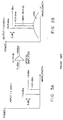
- FIG. 7 shows the configuration of the system comprising, at an optical terminal station 1, an optical transmission signal transmitting unit 1-1; a dummy light generation unit 1-2 for generating a dummy light at an optical terminal station; a level adjustment unit 1-3 for adjusting the level of the dummy light; and a wavelength multiplexing unit 1-4 for combining the optical signals of different wavelengths.
- the level of the optical transmission signal is adjusted.
- FIG. 8 shows the third embodiment of the present invention.
- the output of the optical amplifier can be set constant as described in the description of the prior art.
- a difference in power level after the amplification between the optical signals one of which indicates a high power level while the other indicates a low power level when input to the optical amplifier is transmitted together with the optical signal containing information data when the optical signal is transmitted from the branch station.
- the power level of the optical signal can be adjusted when the optical signal passes through optical amplifiers 60-1 through 60-n and 61-1 through 61-n.
- FIG. 7 shows the configuration of the optical add-drop system in which terminal stations A and B are connected to each other using an up-line and a down-line through a branching unit 51. Also, a line is branched from the branching unit 51, and an up-line and a down-line are provided so that a branch station 53 can transmit and receive an optical signal.
- the transmission lines for connection of the terminal stations A, B, the branch station 53, and the branching unit 51 are provided with optical amplifiers 55-1 through 55-n, 56-1 through 56-n, 57-1 through 57-n, 58-1 through 58-n, 59-1 through 59-n, 60-1 through 60-n, 61-1 through 61-n, and 62-1 through 62-n, each of which has an ALC circuit, thereby amplifying the optical signal when the optical signal is transmitted over a long distance.
- the branching unit 51 has an up-line and a down-line.
- the branch station 53 comprises a receiving unit 1-6 for receiving an optical transmission signal from the down-line; the optical transmission signal transmitting unit 1-1 for transmitting an optical transmission signal; the dummy light generation unit 1-2 for changing the level of a dummy light upon receipt of the signal from the receiving unit 1-6; the wavelength multiplexing unit 1-4 for wavelength-multiplexing the output from the dummy light generation unit 1-2 and the optical transmission signal transmitting unit 1-1; a receiving unit 1-6' for receiving an optical transmission signal from the up-line; the optical transmission signal transmitting unit 1-1' for transmitting an optical transmission signal; the dummy light generation unit 1-2' for changing the level of a dummy light upon receipt of the signal from the receiving unit 1-6'; and the wavelength multiplexing unit 1-4' for wavelength-multiplexing the outputs from the dummy light generation unit 1-2' and the optical transmission signal transmitting unit 1-1'.
- the adjustment between the power level of the optical signal from the branch station 53 and the power level of the optical signal from the terminal station A or B is made using dummy light generation units 1-2 and 1-2' provided in the branch station 53, optical spectrum analyzers 65 and 66 provided in the terminal stations A and B.
- the dummy light generated by the dummy light generation units 1-2 and 1-2' should be different in wavelength from the optical signal.
- the receiving unit of the branch station 53 recognizes that the optical signal transmitted by the branch station 53 is different in power level from the optical signal directly transmitted from the terminal station A or B, then the power level of the dummy light of the dummy light generation units 1-2 and 1-2' is adjusted so that the power level of the optical signal transmitted from the branch station 53 and output from the optical amplifier can be adjusted.
- the power level of the optical signal having each wavelength is constantly monitored by the receiving terminal station, and the power level of the dummy light is adjusted by the branch station 53 so that power level of the optical signal transmitted from the branch station 53 and the power level of the optical signal directly transmitted from the terminal station A or B can be approximately equal to each other when they are combined by the branching unit 51. Therefore, a high system performance can be maintained without deteriorating the operation characteristics as a system only because the optical signal having optically-multiplexed wavelengths indicates a low power level and then a deteriorated S/N ratio.
- FIGs. 9A through 9C show the characteristics of the branching unit shown in FIG. 8.
- FIG. 9A shows the passage characteristics from the transmitting station to the receiving station.
- the incident light from the transmitting station is white light
- FIG. 9A indicates the transmission characteristic around the isolator 72 (FIG. 8).
- FIG. 9A indicates that the optical transmission intensity is lowered around four central wavelengths. It implies that the fiber gratings 73 - 1 through 73 - 4 reflect the light having these wavelengths, and the light is not output to the isolator 72.
- the wavelength other than a specific wavelength keeps unchanged in intensity. Therefore, with the configuration shown in FIG. 8, only the optical signal having a specific wavelength can be selectively prevented from passing.
- FIG. 9C shows the transmission characteristics of the optical signal from the branch station to the receiving station.
- no lights are input from the transmitting station, and a white light is input from the branch station to check what type of wavelength is detected.
- the light input from the branch station is transmitted by the circulator 71 to the fiber gratings 74 - 1 through 74 - 4, and the light having the same wavelength as the case shown in FIG. 9B is reflected. Then, the light is input to the circulator 71 again, and output to the receiving station.
- the light having four different wavelengths is output, and the other lights are output only as low-level noises.
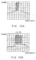
- FIGs. 10A and 10B show the add optical signal input to the branching unit, and show the state of the output light from the branching unit, in which the add optical signal is combined, to the receiving station.
- the optical signal from the branch station as shown in FIG. 10A is combined with the optical signal (2) from the transmitting station without any control, there arises a difference in power level between the optical signal (2) passing from the transmitting station and the optical signal (1) from the branch station as shown in FIG. 10B because the power level of the optical signal from the branch station is different from the power level of the optical signal from the transmitting station.
- the power level of the optical signal from the branch station is higher. That is, the optical signal shown by (1) is an optical signal from the branch station whereas the optical signal shown by (2) is an optical signal passing in the branching unit toward the receiving station.
- the mound-shaped portion indicates the ASE noise.
- FIG. 11A indicates an optical signal containing a dummy light transmitted from the branch station to the branching unit.
- (4) indicates an optical signal containing information.
- (3) indicates a dummy light.
- the power level of the optical signal (4) containing information becomes relatively low.
- the optical signal at a higher power level from the branch station is combined. Therefore, a difference in power level occurs between the optical signal from the branch station and the optical signal from the transmitting station directly to the receiving station.
- the power level of the optical signal (4) containing the information from the branch station can be lowered using the dummy light (3) as shown in FIG. 11A.
- the optical signal corresponding to (3) shown in FIG. 11B is the dummy light which has not been completely dispersed in the branching unit and has been output to the receiving station.
- the power level of the optical signal containing the information transmitted from the branch station is relatively higher. If its power level is lower, the optical signal (4) containing the information can be relatively higher by lowering the power level of the dummy light. Therefore, the power level of the optical signal (5) from the transmitting station can be made to match the power level of the optical signal (4) from the branch station by adjusting the output of the dummy light in the branch station depending on the situation, thereby maintaining the high system performance.
- the above described technology can be applied to the optical wavelength multiplexing communications indicating a higher multiplicity other than the 8-wave transmission, or to the optical wavelength multiplexing communications indicating a lower multiplicity.
- the wavelength of the dummy light does not have to be necessarily shorter, but can be any type as long as it is in the range of the band used to amplify an optical signal in the optical amplifier.
- the optical signal branched by the coupler 90 is input to an optical spectrum analyzer 96, and the power level of the optical signal of each wavelength is checked. The reception level difference of the optical signal is retrieved as information. It is written to the information communications format of the optical signal (for example, POH (pass overhead) of SDH/SONET) in the data format generation unit not shown in FIG. 12, and an electric signal is generated in a way that it is applied to the format with other information signals. These processes are performed by a multiplexer 98 shown in FIG. 12.
- the data signal output from the multiplexer 98 is converted into the optical signals having respective wavelengths by optical transmitting units 99 - 1 through 99 - 3 provided for each channel, each optical signal having each wavelength amplified using post amplifiers 100 - 1 through 100 - 3, and transmitted.
- optical transmitting units 99 - 1 through 99 - 3 provided for each channel, each optical signal having each wavelength amplified using post amplifiers 100 - 1 through 100 - 3, and transmitted.
- generated optical signal having each wavelength is combined by couplers 101 and 102, and transmitted to a terminal station or a branch station through the down-line.
- FIG. 13 is a block diagram showing a part of the branch station.
- the optical signals having two different wavelengths (not limited to two) is transmitted from the branching unit.
- a coupler 118 branches the optical signal.
- Optical filters 119 - 1 and 119 - 2 extract an optical signal having each wavelength.
- the optical signals having respective wavelengths are amplified by preamplifiers 120 - 1 and 120 - 2, and converted into electric signals by optical receivers 121 - 1 and 121 - 2.
- Demultiplexer 122 retrieves the information and transmits the information to the information processing unit not shown in FIG. 13.
- the demultiplexer 122 extracts the information written in the data transmission format of the optical signal obtained by the optical spectrum analyzer (for example, the reception level difference of an optical signal of each wavelength transmitted from the terminal station in the POH area in the SDH/SONET) in the terminal station, and transmits the information to the computer 117.
- the optical spectrum analyzer for example, the reception level difference of an optical signal of each wavelength transmitted from the terminal station in the POH area in the SDH/SONET
- the computer 117 sends the data information to be transmitted as a signal to the optical transmitters 114 - 1 and 114 - 2, and the optical signal having each wavelength is generated.
- the branch station comprises a dummy light generation unit 115 to output a dummy light.
- the optical signal having each wavelength and the dummy light are amplified by post amplifiers 113 - 1 through 113 - 3, and combined by couplers 111 and 112 for transmission.
- the combined optical signal is branched by a coupler 110.
- the coupler 110 branches a light at the rate of, for example, 10:1, passing most of the light as is, and branching a small part of it.
- the optical signal branched by the coupler 110 is input to an optical spectrum analyzer 116, and the power level difference of each wavelength of the optical signal output from the branch station is detected.
- the detection result of the optical spectrum analyser 116 is input to the computer 117, and is compared with the information about the reception level difference at the terminal station extracted by the demultiplexer 122.
- the control signal of the transmission power of the dummy light is transmitted to the post amplifier 113 - 3.
- the reception level difference between the optical signal transmitted from the branch station and the optical signal transmitted to the receiving station without dropping between the terminal station and the branching unit can be monitored.
- the transmission power level of the dummy light is adjusted.
- the difference in power level between the optical signal transmitted from the branch station and combined by the branching unit and the optical signal not dropped can be controlled to be reduced down to almost zero. Therefore, the deterioration in S/N ratio from the power-level-difference can be prevented, and the high system performance can be maintained.
- the optical signal transmitted to the branch station is carried with two different wavelengths.
- the system configuration is not limited to this application, but the wavelength multiplicity of the optical signal transmitted from the terminal station and the wavelength multiplicity of the optical signal transmitted to the branch station should be appropriately determined as necessary in each designing step.
- the difference in power level between the optical signal having each wavelength transmitted from the branch station in a branching unit and the optical signal of each wavelength not dropped can be compensated when they are combined.
- the system performance can be prevented from being lowered by the deterioration of the S/N ratio of the lower power level. Therefore, the optical add-drop system capable of maintaining a high system performance can be provided.
Applications Claiming Priority (6)
| Application Number | Priority Date | Filing Date | Title |
|---|---|---|---|
| JP28282296 | 1996-09-17 | ||
| JP28282296 | 1996-09-17 | ||
| JP282822/96 | 1996-09-17 | ||
| JP20889997 | 1997-08-04 | ||
| JP208899/97 | 1997-08-04 | ||
| JP20889997A JP3821920B2 (ja) | 1996-09-17 | 1997-08-04 | 光通信システム |
Publications (2)
| Publication Number | Publication Date |
|---|---|
| EP0829980A2 true EP0829980A2 (de) | 1998-03-18 |
| EP0829980A3 EP0829980A3 (de) | 2001-09-19 |
Family
ID=26517113
Family Applications (1)
| Application Number | Title | Priority Date | Filing Date |
|---|---|---|---|
| EP97115831A Withdrawn EP0829980A3 (de) | 1996-09-17 | 1997-09-11 | Optisches Kommunikationssystem |
Country Status (4)
| Country | Link |
|---|---|
| US (3) | US6233076B1 (de) |
| EP (1) | EP0829980A3 (de) |
| JP (1) | JP3821920B2 (de) |
| CN (2) | CN1081858C (de) |
Cited By (21)
| Publication number | Priority date | Publication date | Assignee | Title |
|---|---|---|---|---|
| EP0844756A2 (de) * | 1996-11-22 | 1998-05-27 | Nec Corporation | Optisches Übertragungssystem und dazu geeignete Übertragungsvorrichtung |
| EP0949776A2 (de) * | 1998-03-31 | 1999-10-13 | Nec Corporation | Optischer Sender, Optischer Sender mit mehreren Wellenlängen und optisches Übertragungsverfahren |
| EP0959578A2 (de) * | 1998-05-19 | 1999-11-24 | Fujitsu Limited | Wellenlängenmultiplexsystem und entsprechender Abschluss |
| EP0994584A1 (de) * | 1998-10-15 | 2000-04-19 | Alcatel | Zwischenverstärker für ein faseroptische Fernübertragunssystem mit WDM |
| EP1049274A2 (de) * | 1999-04-28 | 2000-11-02 | Nec Corporation | Optischer Zwischenverstärker für Wellenlängenmultiplexsignalen |
| US6574037B2 (en) | 1998-06-16 | 2003-06-03 | Xtera Communications, Inc. | All band amplifier |
| GB2383483A (en) * | 2001-12-05 | 2003-06-25 | Miyagi Nippon Denki Kk | Optical add drop multiplexer system |
| US6587259B2 (en) | 2001-07-27 | 2003-07-01 | Xtera Communications, Inc. | System and method for controlling noise figure |
| US6594071B1 (en) | 2001-10-02 | 2003-07-15 | Xtera Communications, Inc. | Method and apparatus for amplifier control |
| US6646788B2 (en) | 2001-03-16 | 2003-11-11 | Xtera Communications, Inc. | System and method for wide band Raman amplification |
| US6778321B1 (en) | 2002-03-15 | 2004-08-17 | Xtera Communications, Inc. | Fiber optic transmission system for a metropolitan area network |
| US6810214B2 (en) | 2001-03-16 | 2004-10-26 | Xtera Communications, Inc. | Method and system for reducing degradation of optical signal to noise ratio |
| US6813066B2 (en) | 1998-03-24 | 2004-11-02 | The Regents Of The University Of Michigan | Gain control in nonlinear fiber amplifier stages |
| US6819479B1 (en) | 2001-12-20 | 2004-11-16 | Xtera Communications, Inc. | Optical amplification using launched signal powers selected as a function of a noise figure |
| US6819478B1 (en) | 2002-03-15 | 2004-11-16 | Xtera Communications, Inc. | Fiber optic transmission system with low cost transmitter compensation |
| US6825973B1 (en) | 2002-03-15 | 2004-11-30 | Xtera Communications, Inc. | Reducing leading edge transients using co-propagating pumps |
| US6833946B2 (en) | 1996-12-23 | 2004-12-21 | Xtera Communications, Inc. | Optical amplification using polarization diversity pumping |
| US6914717B1 (en) | 1996-12-23 | 2005-07-05 | Xtera Communications, Inc. | Multiple wavelength pumping of raman amplifier stages |
| GB2412516A (en) * | 2004-03-23 | 2005-09-28 | Fujitsu Ltd | Add-drop multiplexer with dummy light return line |
| US7233432B2 (en) | 2001-12-20 | 2007-06-19 | Xtera Communications, Inc. | Pre-emphasized optical communication |
| US7974002B2 (en) | 2002-03-15 | 2011-07-05 | Xtera Communication, Inc. | System and method for managing system margin |
Families Citing this family (48)
| Publication number | Priority date | Publication date | Assignee | Title |
|---|---|---|---|---|
| JP3821920B2 (ja) * | 1996-09-17 | 2006-09-13 | 富士通株式会社 | 光通信システム |
| JP3022359B2 (ja) * | 1996-11-29 | 2000-03-21 | 日本電気株式会社 | 光分波合波装置 |
| JP3112070B2 (ja) * | 1997-04-28 | 2000-11-27 | 日本電気株式会社 | 光ネットワークおよびそのスイッチ制御方法 |
| JP2000004213A (ja) | 1998-06-12 | 2000-01-07 | Nec Corp | 波長分割多重信号光におけるoadm |
| US6597830B1 (en) | 1998-07-01 | 2003-07-22 | Nec Corporation | Matrix optical switch and optical ADM |
| AU4653699A (en) * | 1998-11-06 | 2000-05-29 | Sumitomo Electric Industries, Ltd. | Method and apparatus for optical communication monitoring, optical amplifier system, method of controlling optical amplifier system, and optical communication system |
| JP2001223641A (ja) * | 2000-02-14 | 2001-08-17 | Sumitomo Electric Ind Ltd | 光伝送システム及び光伝送方法 |
| KR100351672B1 (ko) * | 2000-06-12 | 2002-09-11 | 한국과학기술원 | 전광자동이득조절 기능을 갖는 양방향 애드/드롭 광증폭기 |
| US6721509B2 (en) * | 2000-12-05 | 2004-04-13 | Avanex Corporation | Self-adjusting optical add-drop multiplexer and optical networks using same |
| US6922532B2 (en) * | 2000-12-07 | 2005-07-26 | Frederic Simard | Optical performance monitoring for D/WDM networks |
| JP2002280966A (ja) | 2001-03-21 | 2002-09-27 | Nec Miyagi Ltd | Oadmシステムの挿入信号レベル設定システム及びその設定方法 |
| JP5064619B2 (ja) * | 2001-08-10 | 2012-10-31 | 古河電気工業株式会社 | 光伝送装置 |
| US7711775B2 (en) * | 2001-10-24 | 2010-05-04 | Groove Networks, Inc. | Method and apparatus for managing software component downloads and updates |
| US7058301B2 (en) | 2002-02-28 | 2006-06-06 | Bosloy Jonathan L | Apparatus and method for planned wavelength addition and removal in a wavelength division multiplexed system |
| US7153362B2 (en) * | 2002-04-30 | 2006-12-26 | Samsung Electronics Co., Ltd. | System and method for real time deposition process control based on resulting product detection |
| US8750702B1 (en) * | 2002-06-21 | 2014-06-10 | Rockstar Consortium Us Lp | Passive optical loopback |
| JP2005051598A (ja) * | 2003-07-30 | 2005-02-24 | Kddi Submarine Cable Systems Inc | 光伝送システムのアップグレード方法及び光送信装置 |
| JP4237668B2 (ja) * | 2004-04-27 | 2009-03-11 | 京セラ株式会社 | 無線通信システム、基地局装置及び送信電力制御方法 |
| WO2006031340A2 (en) * | 2004-08-11 | 2006-03-23 | Tyco Telecommunications (Us) Inc. | System and method for spectral loading an optical transmission system |
| WO2006135524A2 (en) * | 2005-05-18 | 2006-12-21 | Corning Cable Systems Llc | High density optical fiber distribution enclosure |
| JP2007274482A (ja) * | 2006-03-31 | 2007-10-18 | Fujitsu Ltd | 光伝送装置 |
| US7519258B2 (en) * | 2006-12-21 | 2009-04-14 | Corning Cable Systems Llc | Preconnectorized fiber optic local convergence points |
| JP5076660B2 (ja) * | 2007-06-11 | 2012-11-21 | 日本電気株式会社 | 波長多重伝送装置、制御方法及び制御プログラム |
| US7627214B2 (en) * | 2008-02-08 | 2009-12-01 | Corning Cable Systems Llc | Adjustable optical tap |
| JP5240673B2 (ja) | 2009-03-19 | 2013-07-17 | 日本電気株式会社 | 光信号レベル調整システム及びこれにおける情報解析・制御信号生成装置並びに情報解析・制御信号生成方法 |
| WO2010132656A1 (en) * | 2009-05-14 | 2010-11-18 | Tyco Electronics Subsea Communications Llc | Branching configuration including separate branching unit and predetermined wavelength filter unit and system and method including the same |
| CN101957476B (zh) * | 2009-07-21 | 2013-01-23 | 华为海洋网络有限公司 | 光分插复用器水下光分路器及其对应的光传输方法和系统 |
| JP5387311B2 (ja) * | 2009-10-06 | 2014-01-15 | 日本電気株式会社 | 波長多重光ネットワークシステム及び波長多重光の送受信方法 |
| JP5494669B2 (ja) | 2009-10-16 | 2014-05-21 | 日本電気株式会社 | 光分岐装置、光通信システムおよび光合波方法 |
| US8401391B2 (en) * | 2009-12-08 | 2013-03-19 | Tyco Electronics Subsea Communications Llc | Channel power management in a branched optical communication system |
| WO2011161929A1 (ja) * | 2010-06-24 | 2011-12-29 | 三菱電機株式会社 | 波長多重伝送装置 |
| EP2633354A1 (de) | 2010-10-28 | 2013-09-04 | Corning Cable Systems LLC | Schlagzähe glasfasergehäuse und zugehörige verfahren |
| JP5776254B2 (ja) | 2011-03-25 | 2015-09-09 | 富士通株式会社 | 通信システム、通信装置および通信方法 |
| WO2013042321A1 (ja) * | 2011-09-20 | 2013-03-28 | 日本電気株式会社 | 光増幅制御装置及びその制御方法 |
| US9069151B2 (en) | 2011-10-26 | 2015-06-30 | Corning Cable Systems Llc | Composite cable breakout assembly |
| JP5910089B2 (ja) * | 2012-01-05 | 2016-04-27 | 日本電気株式会社 | 波長多重光伝送システム |
| US8989197B2 (en) * | 2012-04-02 | 2015-03-24 | Nec Laboratories America, Inc. | Reconfigurable branching unit for submarine optical communication networks |
| US8873926B2 (en) | 2012-04-26 | 2014-10-28 | Corning Cable Systems Llc | Fiber optic enclosures employing clamping assemblies for strain relief of cables, and related assemblies and methods |
| CN105052056B (zh) * | 2013-03-15 | 2018-05-22 | 日本电气株式会社 | 光发射/接收设备、光通信系统、以及光发射/接收方法 |
| CN105814817B (zh) | 2013-09-24 | 2019-11-05 | 日本电气株式会社 | 传送装置、传送系统、传送方法和其上存储有程序的存储介质 |
| US9414134B2 (en) * | 2013-10-02 | 2016-08-09 | Nec Corporation | Secure wavelength selective switch-based reconfigurable branching unit for submarine network |
| JP6291799B2 (ja) * | 2013-11-13 | 2018-03-14 | 富士通株式会社 | 光伝送装置及び光伝送方法 |
| US9509113B2 (en) * | 2014-06-17 | 2016-11-29 | Fujitsu Limited | Transient gain cancellation for optical amplifiers |
| JP6481314B2 (ja) * | 2014-09-30 | 2019-03-13 | 富士通株式会社 | 光伝送装置および光伝送システム |
| US9853762B2 (en) * | 2014-12-04 | 2017-12-26 | Ciena Corporation | Automated provisioning and control of shared optical spectrum in submarine optical networks |
| JP6350739B2 (ja) * | 2015-03-18 | 2018-07-04 | 日本電気株式会社 | 光伝送システムとその解析方法、及び、端局装置、管理装置 |
| EP3432489A4 (de) * | 2016-03-14 | 2019-11-20 | Nec Corporation | Optische steuerungsvorrichtung und optische verzweigungsvorrichtung |
| JP6780773B2 (ja) * | 2017-03-29 | 2020-11-04 | 日本電気株式会社 | 通信装置及び通信機器 |
Citations (4)
| Publication number | Priority date | Publication date | Assignee | Title |
|---|---|---|---|---|
| US5311347A (en) * | 1991-07-01 | 1994-05-10 | Fujitsu Limited | Optical communication system with automatic gain control |
| WO1997006616A1 (en) * | 1995-08-04 | 1997-02-20 | Alcatel Alsthom Compagnie Generale D'electricite | Improvements in or relating to optical add/drop wavelength division multiplex systems |
| WO1998008322A1 (en) * | 1996-08-19 | 1998-02-26 | Alcatel Alsthom Compagnie Generale D'electricite | Improvements in or relating to optical add/drop wavelength division multiplex systems |
| EP0844756A2 (de) * | 1996-11-22 | 1998-05-27 | Nec Corporation | Optisches Übertragungssystem und dazu geeignete Übertragungsvorrichtung |
Family Cites Families (15)
| Publication number | Priority date | Publication date | Assignee | Title |
|---|---|---|---|---|
| US4973169A (en) * | 1987-06-24 | 1990-11-27 | Martin Marietta Corporation | Method and apparatus for securing information communicated through optical fibers |
| JP2787820B2 (ja) | 1990-07-20 | 1998-08-20 | キヤノン株式会社 | 波長多重光通信システム及びそこで用いられる光増幅装置 |
| JP2626215B2 (ja) | 1990-08-28 | 1997-07-02 | 日本電気株式会社 | 半導体光増幅器の利得安定化制御方式 |
| JP2900567B2 (ja) | 1990-09-07 | 1999-06-02 | 日本電気株式会社 | 半導体光増幅装置 |
| CA2059493C (en) * | 1991-01-17 | 1996-11-12 | Yoshiyuki Inoue | Feeding system and feeding method for a submarine cable communication system |
| JP2940194B2 (ja) | 1991-03-22 | 1999-08-25 | 日本電気株式会社 | 光直接増幅方式 |
| DE4109683A1 (de) * | 1991-03-23 | 1992-09-24 | Standard Elektrik Lorenz Ag | System fuer optische signaluebertragung, insbesondere optisches kabelfernsehsystem, mit ueberwachungs- und dienstkanaleinrichtung |
| JP3164870B2 (ja) | 1992-02-12 | 2001-05-14 | 住友大阪セメント株式会社 | 光ファイバーアンプの利得制御装置 |
| JPH05327662A (ja) | 1992-05-25 | 1993-12-10 | Matsushita Electric Ind Co Ltd | 波長多重光源 |
| JPH0746224A (ja) * | 1992-10-09 | 1995-02-14 | Philips Electron Nv | 送信システム及び受信機 |
| EP0616442B1 (de) * | 1993-03-19 | 1997-11-26 | Siemens Aktiengesellschaft | Sende-/Empfangsschaltung in einem passiven optischen Telekommunikationssystem |
| JP2551371B2 (ja) * | 1993-12-01 | 1996-11-06 | 日本電気株式会社 | 光中継器 |
| JP3193220B2 (ja) | 1993-12-28 | 2001-07-30 | 安藤電気株式会社 | 光周波数制御装置 |
| US6025947A (en) * | 1996-05-02 | 2000-02-15 | Fujitsu Limited | Controller which controls a variable optical attenuator to control the power level of a wavelength-multiplexed optical signal when the number of channels are varied |
| JP3821920B2 (ja) * | 1996-09-17 | 2006-09-13 | 富士通株式会社 | 光通信システム |
-
1997
- 1997-08-04 JP JP20889997A patent/JP3821920B2/ja not_active Expired - Lifetime
- 1997-09-05 US US08/923,934 patent/US6233076B1/en not_active Expired - Lifetime
- 1997-09-11 EP EP97115831A patent/EP0829980A3/de not_active Withdrawn
- 1997-09-16 CN CN97118485A patent/CN1081858C/zh not_active Expired - Lifetime
-
2001
- 2001-02-09 US US09/779,624 patent/US6414770B2/en not_active Expired - Lifetime
- 2001-10-25 CN CN01137200.1A patent/CN1392685A/zh active Pending
-
2002
- 2002-04-30 US US10/134,432 patent/US6721507B2/en not_active Expired - Lifetime
Patent Citations (4)
| Publication number | Priority date | Publication date | Assignee | Title |
|---|---|---|---|---|
| US5311347A (en) * | 1991-07-01 | 1994-05-10 | Fujitsu Limited | Optical communication system with automatic gain control |
| WO1997006616A1 (en) * | 1995-08-04 | 1997-02-20 | Alcatel Alsthom Compagnie Generale D'electricite | Improvements in or relating to optical add/drop wavelength division multiplex systems |
| WO1998008322A1 (en) * | 1996-08-19 | 1998-02-26 | Alcatel Alsthom Compagnie Generale D'electricite | Improvements in or relating to optical add/drop wavelength division multiplex systems |
| EP0844756A2 (de) * | 1996-11-22 | 1998-05-27 | Nec Corporation | Optisches Übertragungssystem und dazu geeignete Übertragungsvorrichtung |
Non-Patent Citations (1)
| Title |
|---|
| ZYSKIND J L ET AL: "Fast link control protection for surviving channels in multiwavelength optical networks" ECOC '96. 22ND EUROPEAN CONFERENCE ON OPTICAL COMMUNICATION (IEEE CAT. NO.96TH8217), PROCEEDINGS OF EUROPEAN CONFERENCE ON OPTICAL COMMUNICATION, OSLO, NORWAY, 15-19 SEPT. 1996, 15 - 19 September 1996, pages 49-52 vol.5, XP000997376 1996, Kjeller, Norway, Telenor, Norway ISBN: 82-423-0418-1 * |
Cited By (29)
| Publication number | Priority date | Publication date | Assignee | Title |
|---|---|---|---|---|
| EP0844756A2 (de) * | 1996-11-22 | 1998-05-27 | Nec Corporation | Optisches Übertragungssystem und dazu geeignete Übertragungsvorrichtung |
| EP0844756A3 (de) * | 1996-11-22 | 2001-09-26 | Nec Corporation | Optisches Übertragungssystem und dazu geeignete Übertragungsvorrichtung |
| US6914717B1 (en) | 1996-12-23 | 2005-07-05 | Xtera Communications, Inc. | Multiple wavelength pumping of raman amplifier stages |
| US6833946B2 (en) | 1996-12-23 | 2004-12-21 | Xtera Communications, Inc. | Optical amplification using polarization diversity pumping |
| US6813066B2 (en) | 1998-03-24 | 2004-11-02 | The Regents Of The University Of Michigan | Gain control in nonlinear fiber amplifier stages |
| EP0949776A2 (de) * | 1998-03-31 | 1999-10-13 | Nec Corporation | Optischer Sender, Optischer Sender mit mehreren Wellenlängen und optisches Übertragungsverfahren |
| EP0949776A3 (de) * | 1998-03-31 | 2001-01-17 | Nec Corporation | Optischer Sender, Optischer Sender mit mehreren Wellenlängen und optisches Übertragungsverfahren |
| EP0959578A2 (de) * | 1998-05-19 | 1999-11-24 | Fujitsu Limited | Wellenlängenmultiplexsystem und entsprechender Abschluss |
| EP0959578A3 (de) * | 1998-05-19 | 2001-09-26 | Fujitsu Limited | Wellenlängenmultiplexsystem und entsprechender Abschluss |
| US6404523B1 (en) | 1998-05-19 | 2002-06-11 | Fujitsu Limited | Wavelength division multiplexing system and its termination |
| US6574037B2 (en) | 1998-06-16 | 2003-06-03 | Xtera Communications, Inc. | All band amplifier |
| EP0994584A1 (de) * | 1998-10-15 | 2000-04-19 | Alcatel | Zwischenverstärker für ein faseroptische Fernübertragunssystem mit WDM |
| EP1049274A2 (de) * | 1999-04-28 | 2000-11-02 | Nec Corporation | Optischer Zwischenverstärker für Wellenlängenmultiplexsignalen |
| EP1049274A3 (de) * | 1999-04-28 | 2004-07-28 | Nec Corporation | Optischer Zwischenverstärker für Wellenlängenmultiplexsignalen |
| US6646788B2 (en) | 2001-03-16 | 2003-11-11 | Xtera Communications, Inc. | System and method for wide band Raman amplification |
| US6810214B2 (en) | 2001-03-16 | 2004-10-26 | Xtera Communications, Inc. | Method and system for reducing degradation of optical signal to noise ratio |
| US6587259B2 (en) | 2001-07-27 | 2003-07-01 | Xtera Communications, Inc. | System and method for controlling noise figure |
| US6594071B1 (en) | 2001-10-02 | 2003-07-15 | Xtera Communications, Inc. | Method and apparatus for amplifier control |
| GB2383483B (en) * | 2001-12-05 | 2004-03-31 | Miyagi Nippon Denki Kk | Optical add drop multiplexer system |
| GB2383483A (en) * | 2001-12-05 | 2003-06-25 | Miyagi Nippon Denki Kk | Optical add drop multiplexer system |
| US6819479B1 (en) | 2001-12-20 | 2004-11-16 | Xtera Communications, Inc. | Optical amplification using launched signal powers selected as a function of a noise figure |
| US7233432B2 (en) | 2001-12-20 | 2007-06-19 | Xtera Communications, Inc. | Pre-emphasized optical communication |
| US6819478B1 (en) | 2002-03-15 | 2004-11-16 | Xtera Communications, Inc. | Fiber optic transmission system with low cost transmitter compensation |
| US6825973B1 (en) | 2002-03-15 | 2004-11-30 | Xtera Communications, Inc. | Reducing leading edge transients using co-propagating pumps |
| US6778321B1 (en) | 2002-03-15 | 2004-08-17 | Xtera Communications, Inc. | Fiber optic transmission system for a metropolitan area network |
| US7974002B2 (en) | 2002-03-15 | 2011-07-05 | Xtera Communication, Inc. | System and method for managing system margin |
| GB2412516A (en) * | 2004-03-23 | 2005-09-28 | Fujitsu Ltd | Add-drop multiplexer with dummy light return line |
| FR2868224A1 (fr) * | 2004-03-23 | 2005-09-30 | Fujitsu Ltd | Appareil de transmission optique et systeme de transmission optique |
| GB2412516B (en) * | 2004-03-23 | 2007-09-05 | Fujitsu Ltd | Optical transmission apparatus and optical transmission system |
Also Published As
| Publication number | Publication date |
|---|---|
| US6414770B2 (en) | 2002-07-02 |
| CN1081858C (zh) | 2002-03-27 |
| US20020126353A1 (en) | 2002-09-12 |
| CN1392685A (zh) | 2003-01-22 |
| JPH10150433A (ja) | 1998-06-02 |
| EP0829980A3 (de) | 2001-09-19 |
| CN1177240A (zh) | 1998-03-25 |
| US20010015838A1 (en) | 2001-08-23 |
| US6721507B2 (en) | 2004-04-13 |
| JP3821920B2 (ja) | 2006-09-13 |
| US6233076B1 (en) | 2001-05-15 |
Similar Documents
| Publication | Publication Date | Title |
|---|---|---|
| EP0829980A2 (de) | Optisches Kommunikationssystem | |
| EP0959578B1 (de) | Wellenlängenmultiplexsystem und entsprechender Abschluss | |
| US5742416A (en) | Bidirectional WDM optical communication systems with bidirectional optical amplifiers | |
| KR100789095B1 (ko) | 저밀도 파장 다중 광 전송 시스템 및 저밀도 파장 다중 광전송 방법 | |
| US20040228602A1 (en) | Optical device including dynamic channel equalization | |
| US6599039B1 (en) | Optical transmission monitoring apparatus, optical transmission monitoring method, optical amplification system, method of controlling optical amplification system, and optical transmission system | |
| US6563978B2 (en) | Optical transmission system and optical coupler/branching filter | |
| US8032028B2 (en) | Optical add/drop device | |
| US7689131B2 (en) | WDM system | |
| US20120121267A1 (en) | Optical add-drop multiplexer branching unit and corresponding optical transmission method and system | |
| US6512613B1 (en) | WDM transmission repeater, WDM transmission system and WDM transmission method | |
| GB2324667A (en) | Wavelength multiplexed optical signal amplification control system | |
| CN114124287A (zh) | 光信号控制方法及装置、光传输节点和光传输系统 | |
| US7061670B2 (en) | Optical fiber amplifier having automatic power control function and automatic power control method | |
| EP1126635A1 (de) | Cdma mobile kommunikationsstation, cdma mobile telekommunikationsanordnung, und cdma paket übertragungsverfahren | |
| CN112217568B (zh) | 一种光信号处理装置以及通信系统 | |
| US6646792B2 (en) | Light amplifier and light transmission system using the same | |
| CN116264480A (zh) | 一种光传输设备和系统 | |
| US6577416B1 (en) | Channel control in a wavelength division multiplexed communications network | |
| JP2000312185A (ja) | 波長多重光伝送用光中継増幅器およびこれを用いた波長多重光伝送装置 | |
| EP0994595A2 (de) | Wellenlängemultiplexer/-demultiplexer und optisches Übertragungssystem | |
| WO2000051278A1 (en) | Wdm ring transmission system having amplified dropped channels | |
| JPH11252048A (ja) | 波長多重光伝送システム | |
| JPH05191380A (ja) | 波長多重伝送方式 |
Legal Events
| Date | Code | Title | Description |
|---|---|---|---|
| PUAI | Public reference made under article 153(3) epc to a published international application that has entered the european phase |
Free format text: ORIGINAL CODE: 0009012 |
|
| AK | Designated contracting states |
Kind code of ref document: A2 Designated state(s): AT BE CH DE DK ES FI FR GB GR IE IT LI LU MC NL PT SE Kind code of ref document: A2 Designated state(s): DE FR GB IT |
|
| PUAL | Search report despatched |
Free format text: ORIGINAL CODE: 0009013 |
|
| AK | Designated contracting states |
Kind code of ref document: A3 Designated state(s): AT BE CH DE DK ES FI FR GB GR IE IT LI LU MC NL PT SE |
|
| 17P | Request for examination filed |
Effective date: 20020125 |
|
| AKX | Designation fees paid |
Free format text: DE FR GB IT |
|
| GRAP | Despatch of communication of intention to grant a patent |
Free format text: ORIGINAL CODE: EPIDOSNIGR1 |
|
| INTG | Intention to grant announced |
Effective date: 20160603 |
|
| STAA | Information on the status of an ep patent application or granted ep patent |
Free format text: STATUS: THE APPLICATION HAS BEEN WITHDRAWN |
|
| 18W | Application withdrawn |
Effective date: 20160930 |