EP0994595A2 - Wellenlängemultiplexer/-demultiplexer und optisches Übertragungssystem - Google Patents
Wellenlängemultiplexer/-demultiplexer und optisches Übertragungssystem Download PDFInfo
- Publication number
- EP0994595A2 EP0994595A2 EP99402500A EP99402500A EP0994595A2 EP 0994595 A2 EP0994595 A2 EP 0994595A2 EP 99402500 A EP99402500 A EP 99402500A EP 99402500 A EP99402500 A EP 99402500A EP 0994595 A2 EP0994595 A2 EP 0994595A2
- Authority
- EP
- European Patent Office
- Prior art keywords
- optical
- input
- light
- output port
- demultiplexer
- Prior art date
- Legal status (The legal status is an assumption and is not a legal conclusion. Google has not performed a legal analysis and makes no representation as to the accuracy of the status listed.)
- Withdrawn
Links
Images


Classifications
-
- G—PHYSICS
- G02—OPTICS
- G02B—OPTICAL ELEMENTS, SYSTEMS OR APPARATUS
- G02B6/00—Light guides; Structural details of arrangements comprising light guides and other optical elements, e.g. couplings
- G02B6/24—Coupling light guides
- G02B6/26—Optical coupling means
- G02B6/28—Optical coupling means having data bus means, i.e. plural waveguides interconnected and providing an inherently bidirectional system by mixing and splitting signals
- G02B6/293—Optical coupling means having data bus means, i.e. plural waveguides interconnected and providing an inherently bidirectional system by mixing and splitting signals with wavelength selective means
- G02B6/29379—Optical coupling means having data bus means, i.e. plural waveguides interconnected and providing an inherently bidirectional system by mixing and splitting signals with wavelength selective means characterised by the function or use of the complete device
- G02B6/2938—Optical coupling means having data bus means, i.e. plural waveguides interconnected and providing an inherently bidirectional system by mixing and splitting signals with wavelength selective means characterised by the function or use of the complete device for multiplexing or demultiplexing, i.e. combining or separating wavelengths, e.g. 1xN, NxM
-
- G—PHYSICS
- G02—OPTICS
- G02B—OPTICAL ELEMENTS, SYSTEMS OR APPARATUS
- G02B6/00—Light guides; Structural details of arrangements comprising light guides and other optical elements, e.g. couplings
- G02B6/24—Coupling light guides
- G02B6/26—Optical coupling means
- G02B6/28—Optical coupling means having data bus means, i.e. plural waveguides interconnected and providing an inherently bidirectional system by mixing and splitting signals
- G02B6/293—Optical coupling means having data bus means, i.e. plural waveguides interconnected and providing an inherently bidirectional system by mixing and splitting signals with wavelength selective means
- G02B6/29304—Optical coupling means having data bus means, i.e. plural waveguides interconnected and providing an inherently bidirectional system by mixing and splitting signals with wavelength selective means operating by diffraction, e.g. grating
- G02B6/29316—Light guides comprising a diffractive element, e.g. grating in or on the light guide such that diffracted light is confined in the light guide
- G02B6/29317—Light guides of the optical fibre type
- G02B6/29319—With a cascade of diffractive elements or of diffraction operations
- G02B6/2932—With a cascade of diffractive elements or of diffraction operations comprising a directional router, e.g. directional coupler, circulator
-
- H—ELECTRICITY
- H04—ELECTRIC COMMUNICATION TECHNIQUE
- H04B—TRANSMISSION
- H04B10/00—Transmission systems employing electromagnetic waves other than radio-waves, e.g. infrared, visible or ultraviolet light, or employing corpuscular radiation, e.g. quantum communication
- H04B10/29—Repeaters
- H04B10/291—Repeaters in which processing or amplification is carried out without conversion of the main signal from optical form
-
- H—ELECTRICITY
- H04—ELECTRIC COMMUNICATION TECHNIQUE
- H04J—MULTIPLEX COMMUNICATION
- H04J14/00—Optical multiplex systems
- H04J14/02—Wavelength-division multiplex systems
-
- H—ELECTRICITY
- H04—ELECTRIC COMMUNICATION TECHNIQUE
- H04J—MULTIPLEX COMMUNICATION
- H04J14/00—Optical multiplex systems
- H04J14/02—Wavelength-division multiplex systems
- H04J14/0201—Add-and-drop multiplexing
-
- H—ELECTRICITY
- H04—ELECTRIC COMMUNICATION TECHNIQUE
- H04J—MULTIPLEX COMMUNICATION
- H04J14/00—Optical multiplex systems
- H04J14/02—Wavelength-division multiplex systems
- H04J14/0201—Add-and-drop multiplexing
- H04J14/0202—Arrangements therefor
- H04J14/0213—Groups of channels or wave bands arrangements
-
- H—ELECTRICITY
- H04—ELECTRIC COMMUNICATION TECHNIQUE
- H04J—MULTIPLEX COMMUNICATION
- H04J14/00—Optical multiplex systems
- H04J14/02—Wavelength-division multiplex systems
- H04J14/0221—Power control, e.g. to keep the total optical power constant
-
- G—PHYSICS
- G02—OPTICS
- G02B—OPTICAL ELEMENTS, SYSTEMS OR APPARATUS
- G02B6/00—Light guides; Structural details of arrangements comprising light guides and other optical elements, e.g. couplings
- G02B6/24—Coupling light guides
- G02B6/26—Optical coupling means
- G02B6/28—Optical coupling means having data bus means, i.e. plural waveguides interconnected and providing an inherently bidirectional system by mixing and splitting signals
- G02B6/293—Optical coupling means having data bus means, i.e. plural waveguides interconnected and providing an inherently bidirectional system by mixing and splitting signals with wavelength selective means
- G02B6/29346—Optical coupling means having data bus means, i.e. plural waveguides interconnected and providing an inherently bidirectional system by mixing and splitting signals with wavelength selective means operating by wave or beam interference
- G02B6/29361—Interference filters, e.g. multilayer coatings, thin film filters, dichroic splitters or mirrors based on multilayers, WDM filters
-
- H—ELECTRICITY
- H04—ELECTRIC COMMUNICATION TECHNIQUE
- H04B—TRANSMISSION
- H04B2210/00—Indexing scheme relating to optical transmission systems
- H04B2210/25—Distortion or dispersion compensation
- H04B2210/258—Distortion or dispersion compensation treating each wavelength or wavelength band separately
Definitions
- the present invention relates to a wavelength multiplexer/ demultiplexer and optical transmission apparatus, which are used in an optical communication system.
- a wavelength multiplexer/ demultiplexer and optical transmission apparatus which is used in a WDM (wavelength-division multiplexed) optical communication system, and which is applicable to a future system where the wavelength bands are expanded.
- optical transmission system it is unnecessary to perform a process of converting an optical signal into an electric signal by a relay station and then converting it back into an optical signal, when using an optical amplifier as a repeater. This allows the scale of the relay station to be downsized, and the communication cost to be lowered.
- an optical fiber amplifier which is mostly represented by an erbium-doped optical fiber (EDFA), in particular, have rapidly been increasing. This allows the optical fiber to transmit a long distance. At the present time, it has been taken into considerable consideration for further increasing the transmission capacity and managing the transmission status.
- EDFA erbium-doped optical fiber
- a standard wavelength band as currently used for the optical transmission through a main line has 1550 nm as a center and ranges within the vicinity of it. Even though this wavelength band is limited to the allowable wavelength of a repeater amplifier, the recent rapid progress in the optical amplifier allows an optically relaying transmission using the wavelength band. which has 1580 nm as a center and ranges within the vicinity of it.
- the present technique cannot simultaneously amplify the lights of the entire wavelength band, which flow through an optical transmission line. Therefore, it is necessary to demultiplex the wavelength band of lights that flow through the optical transmission line, and also to place optical amplifiers for the respective wavelength bands.
- the transmission capacity is increased with the above arrangement, it is necessary to temporarily halt providing the conventional services. It is, however, very difficult to halt this operation because it may have a bad influence on the users.
- the multiplexer/ demultiplexer can deal with wavelengths that will be used in the future.
- the optical node such as the optical demultiplexing/inserting circuit or optical cross-connector, is also affected.
- the optical node is made up of optical devices such as an optical multiplexer/ demultiplexer. an optical amplifier, and a transmitting light source, which are greatly dependent upon wavelengths. Consequently, an expansion of the wavelength band requires an additional optical node as well as an optical amplifier.
- the objective of the present invention is to provide an optical multiplexer/ demultiplexer and optical transmission apparatus, which allow an addition of a desired wavelength band without halting the operation of the conventional optical transmission services.
- an optical multiplexer/ demultiplexer demultiplexes an optical signal input from a first input/output port and then outputs it to a second and a third input/output port, and multiplexes optical signals input from the second and the third input/output port, and then outputs its resulting signal from the first input/output port.
- This optical multiplexer/ demultiplexer is comprised of an optical filter, which passes through a predetermined wavelength of light of the optical signals and reflects the other wavelengths of light.
- an optical transmission apparatus processes a predetermined wavelength of light of WDM optical signals input from a first input terminal and then outputs it from a first output terminal; and outputs a light of the WDM optical signals from a second output terminal, where this light does not belong to the wavelength band; and outputs the light not belonging to the wavelength band, from the first output terminal.
- This optical transmission apparatus is comprised of: a first optical multiplexer/ demultiplexer, where its first input/output port is connected to the first input terminal, whereas its third input/output port is connected to the second output terminal: a functional optical unit, which processes a light output from a second input/output port of the first optical multiplexer/ demultiplexer and then outputs it: and a second optical multiplexer/ demultiplexer, where its second input/output port is connected to an output terminal of the functional optical unit. its third input/output port is connected to the second input terminal, and its first input/output port is connected to the first output terminal.
- an optical multiplexer/ demultiplexer In an optical transmission system, when a transmission is started using a new transmitting wavelength band, it is necessary for an optical multiplexer/ demultiplexer to separate a new wavelength band of optical signals from the conventional wavelength band of optical signals, as shown in Fig. 1. An additional optical amplifier dealing with the new wavelength band is also necessary. In order to place an additional optical amplifier without halting the conventional services, it is necessary to place an optical multiplexer/ demultiplexer beforehand, in anticipation of a future to-be-used wavelength band.
- the conventional optical multiplexer/ demultiplexer such as the arrayed waveguide grating or WDM coupler, cannot adjust wavelengths of light, which are to be multiplexed and demultiplexed.
- wavelengths of light which can be multiplexed and demultiplexed, are determined.
- the multiplexer/ demultiplexer can deal with wavelengths that will be used in a future.
- the optical node such as the optical demultiplexing/inserting circuit or optical cross-connector
- the optical node is made up of optical devices such as an optical multiplexer/ demultiplexer, an optical amplifier, and a transmitting light source, which are greatly dependent upon wavelengths. Consequently, an expansion of the wavelength band requires placing an additional optical node as with the optical amplifier.
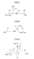
- Fig. 3 illustrates the configuration of an optical demultiplexer, according to the first embodiment of the present invention.
- the optical demultiplexer of Fig. 3 includes a fiber Bragg grating 151.
- a fiber Bragg grating 151, connected to the optical transmission line 110, has a property passing through only a light 1550 nm in wavelength. Conversely, the other wavelengths of light are reflected. Accordingly, the light 1550 nm in wavelength is output to an optical transmission line 120, whereas the light 1580 nm in wavelength is output to an optical transmission line 111.
- the wavelength-division-multiplexed lights can be demultiplexed into the respective wavelengths of 1550 nm and 1580 nm.
- the fiber Bragg grating 151 has a property reflecting all lights except for the light 1550 nm in wavelength. Therefore, any light, wavelength-division-multiplexed with the light 1550 nm in wavelength, including the light 1580 nm in wavelength, can be demultiplexed in the same way.
- Fig. 4 illustrates the configuration of an optical multiplexer, according to the second embodiment of the present invention.
- the optical multiplexer of Fig. 4 includes a fiber Bragg grating 151.
- a light 1550 nm in wavelength is transmitted to an optical transmission line 110 of Fig. 4, whereas a light 1580 nm in wavelength is transmitted to an optical transmission line 112.
- a fiber Bragg grating 151. connected to the optical transmission line 110, has a property passing through only a light 1550 nm in wavelength. Conversely, the other wavelengths of light are reflected. Therefore, the lights 1550 nm and 1580 nm in wavelength, which are multiplexed, are transmitted through an optical transmission line 120.
- the wavelength of light which is multiplexed with the light 1550 nm in wavelength is not limited to 1580 nm, but it can be any other wavelength.
- An optical filter which passes through one band of light and reflects the other bands of light, can be used in place of the fiber Bragg grating, as in the first and the second embodiments.
- a Fabry-Perot optical filter, etc. can be used as the optical filter.
- Fig. 5 illustrates the configuration of an optical demultiplexer, according to the third embodiment of the present invention.
- the optical demultiplexer of Fig. 5 is comprised of a fiber Bragg grating 152 and an optical circulator 60.
- the optical circulator 60 connected to the optical transmission line 110, outputs the wavelength-division-multiplexed light to an optical transmission line 111.
- a fiber Bragg grating 152 connected to the optical transmission line 111, has a property reflecting only a light 1550 nm in wavelength. Conversely, the other wavelengths of light are passed through. Accordingly, the light 1550 nm in wavelength is output to an optical transmission line 120, whereas the light 1580 nm in wavelength is output to an optical transmission line 111.
- the wavelength-division-multiplexed lights can be demultiplexed. Even in this embodiment, along with the light 1550 nm in wavelength, any wavelength of light can be dealt with in place of the light 1580 nm in wavelength.
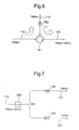
- Fig. G illustrates the configuration of an optical multiplexer, according to the fourth embodiment of the present invention.
- the optical multiplexer of Fig. 6 is comprised of a fiber Bragg grating 152 and an optical circulator 61.
- a light 1550 nm in wavelength is transmitted to an optical transmission line 110 in Fig. 6, whereas a light 1580 nm in wavelength is transmitted to an optical transmission line 112.
- An optical circulator 61 connected to the optical transmission line 110, outputs the light 1550 nm in wavelength to the optical transmission line 112.
- a fiber Bragg grating 152 connected to the optical transmission line 112, has a property, reflecting only a light 1550 nm in wavelength. Conversely, the other wavelengths of light are passed through. Therefore, the lights 1550 nm and 1580 nm in wavelength, which are multiplexed, are transmitted to an optical transmission line 120. Even in this embodiment, along with the light 1550 nm in wavelength, any wavelength of light can be dealt with in place of the light 1580 nm in wavelength.
- the present invention is not limited to the wavelength of 1580 nm, and any other wavelength band can also be used. Therefore, the light 1550 nm in wavelength can be multiplexed with any other wavelength band of light using the above optical multiplexer/ demultiplexer. This allows the system to further deal with a future expansion of the wavelength band.
- Fig. 7 illustrates the configuration of an optical demultiplexer, according to the fifth embodiment of the present invention.
- the optical demultiplexer of Fig. 7 is comprised of an optical isolator 250. an optical power divider 350, and fiber Bragg gratings 152 and 153.
- Two lights with their respective wavelengths of 1550 nm and 1580 nm, which are wavelength-division-multiplexed, are transmitted through an optical transmission line 110 in Fig 7. They enter an optical isolator 250, connected to the optical transmission line 110. and then enter an optical power divider 350, where they are demultiplexed.
- a fiber Bragg grating 153 has a property passing through only a light 1550 nm in wavelength. Conversely, the other wavelengths of light are reflected.
- the light 1550 nm in wavelength is output to an optical transmission line 122.
- the fiber Bragg grating 152 has a property passing through only a light 1580 nm in wavelength.
- the other wavelengths of light are reflected.
- the light 1580 nm in wavelength is output to an optical transmission line 121. In this manner as described above, the wavelength-division-multiplexed lights can be demultiplexed.
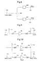
- Fig. 8 illustrates the configuration of an optical demultiplexer, according to the sixth embodiment of the present invention.
- the optical demultiplexer of Fig. 8 is comprised of optical filters 400 and 401, and an optical power divider 350.
- Two lights with their respective wavelengths of 1550 nm and 1580 nm, which are wavelength-division-multiplexed, are transmitted through an optical transmission line 110 in Fig. 8.
- an optical power divider 350 connected to the optical transmission line 110, splits them.
- An optical filter 400 has a property passing through only a light 1580 nm in wavelength. Conversely, the other wavelengths of light are absorbed. Accordingly, the light 1580 nm in wavelength is output to an optical transmission line 121.
- an optical filter 401 has a property passing through only a light 1550 nm in wavelength. Conversely, the other wavelengths of light are reflected. As a result, the light 1550 nm in wavelength is output to an optical transmission line 122. In this manner as described above, the wavelength-division-multiplexed lights can be demultiplexed. It is noted that a band-pass filter such as a multi-layered dielectric optical filter, Fabry-Perot optical filter, etc. can be used for the optical filters 400 and 401.
- the present invention is not limited to these two wavelengths of light.
- the wavelength bands in vicinity of the wavelengths 1550 nm and 1580 nm can also be dealt with by properly setting a passing band widths of the fiber Bragg grating and wavelength filter.
- the present invention is not limited to the wavelength bands of 1550 nm and 1580 nm. A combination with, for example, a wavelength band of 1300 nm can also be provided.
- the transmission band for the current optical communication through a main line is within the vicinity of 1550 nm.
- placing the above optical multiplexer/ demultiplexer somewhere along the transmission line beforehand allows an upgrading of the transmission services using the conventional wavelength band of 1550 nm, without halting these services, when there are demands for transmitting using another wavelength band in the future.
- optical demultiplexer In the fifth and the sixth embodiment, only the optical demultiplexer has been described. However, an optical multiplexer can also be structured using the identical idea. Furthermore, any combination of the optical demultiplexer and optical multiplexer as described in the first to the sixth embodiment can be used. This combination should be suitably changed according to the situation.
- Fig. 9 illustrates the configuration of a relaying optical amplifier, according to the seventh embodiment of the present invention.
- the relaying optical amplifier of Fig. 9 is comprised of an optical amplifier 50 and fiber Bragg gratings 151 and 152.
- a light 1550 nm in wavelength is transmitted to an optical transmission line 110 in Fig. 9.
- the transmitted light is then amplified by the optical amplifier 50, and output to an optical transmission line 120.
- the fiber Bragg gratings 151 and 152 have a property passing through only a light 1550 nm in wavelength. Conversely, the other wavelengths of light are reflected. Therefore, it is possible to assign other wavelength bands to respective optical transmission lines 111 and 112.
- an optical amplifier 56 using a wavelength band of 1580 nm as well as the conventional wavelength band of 1550 nm is placed, so that its transmission capacity can be increased.
- This arrangement allows an expansion of the wavelength band.
- Lights 1550 nm and 1580 nm in wavelength are demultiplexed, amplified by the respective optical amplifiers corresponding to these wavelength bands, and then multiplexed and output to the optical transmission line 120.
- a fiber Bragg grating 154, connected to the optical transmission line 110, has a property passing through only a light 1580 nm in wavelength. Conversely, the other wavelengths of light are reflected. Therefore, another wavelength band of light can be assigned to each of the optical transmission lines 113 and 114.
- Fig. 11 illustrates the configuration where a managing/controlling optical signal processing apparatus 90 using another wavelength band, which is an optical node, is placed in addition to the conventional arrangement for an optical transmission, so as to extend its function.
- the lights 1550 nm and 1310 nm in wavelength, which flow through the optical transmission line, are demultiplexed.
- An optical amplifier 50 then amplifies the light 1550 nm in wavelength.
- the light 1310 nm in wavelength is information-processed by the managing/controlling optical signal processing apparatus 90, and then multiplexed and output to an optical transmission line 120.
- a fiber Bragg grating 156 connected to an optical line 111, has a property passing through only a light 1310 nm in wavelength. Conversely, the other wavelengths of lights are reflected. Therefore, another wavelength band of light can be assigned to each of the optical transmission lines 113 and 114.
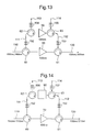
- Fig. 12 illustrates the configuration of a relaying optical amplifier, according to the eighth embodiment of the present invention.
- the relaying optical amplifier of Fig. 12 is comprised of an optical amplifier 50.
- a light 1550 nm in wavelength is transmitted to an optical transmission line 110 in Fig. 12. Afterwards, the transmitted light enters the optical circulator 60. and is then output to the optical transmission line 111.
- a fiber Bragg grating 152 connected to the optical transmission line 111, has a property reflecting only a light 1550 nm in wavelength. Conversely, the other wavelengths of light are passed through. Therefore, the light 1550 nm in wavelength enters the optical amplifier 50. After it is amplified, the amplified light enters the optical circulator 61, and is then output to an optical transmission line 112.
- the fiber Bragg grating 152 has a property reflecting only a light 1550 nm in wavelength. Conversely, the other wavelengths of light are passed through. As a result, the light 1550 nm in wavelength is output to the optical transmission line 120. Therefore, another wavelength band of light can be assigned to each of the optical transmission lines 111 and 112.
- Fig. 13 illustrates the configuration where an optical amplifier 56 for a wavelength band of 1580 nm is placed in addition to the conventional arrangement for the wavelength band of 1550 nm, so as to increase the transmission capacity.
- This arrangement allows an expansion of the wavelength band.
- Lights 1550 nm and 1580 nm in wavelength, which are transmitted through the optical transmission line. are demultiplexed, amplified by the respective optical amplifiers corresponding to these wavelength bands, and then multiplexed and output to the optical transmission line 120.
- a fiber Bragg grating 154 connected to the optical transmission line 113, has a property reflecting only a light 1580 nm in wavelength. Conversely, the other wavelengths of light are passed through. Therefore, another wavelength band of light can be assigned to each of the optical transmission lines 113 and 114.
- Fig. 14 illustrates the configuration where a managing/controlling optical signal processing apparatus 90 for another wavelength band is placed in addition to the conventional arrangement for an optical transmission, so as to expand its function.
- the managing/controlling optical signal processing apparatus 90 monitors management information which is sent using the wavelength band of 1310 nm, and updates as necessary, thus transmitting it to a downstream node.
- the lights 1550 nm and 1310 nm in wavelength, which flow through the optical transmission line. are demultiplexed.
- An optical amplifier 50 then amplifies the light 1550 nm in wavelength.
- the light 1310 nm in wavelength is information-processed by the managing/controlling optical signal processing apparatus 90, and then multiplexed and output to an optical transmission line 120.
- a fiber Bragg grating 156 connected to an optical line 113, has a property reflecting only a light 1310 nm in wavelength. Conversely, the other wavelengths of light are passed through. Therefore, another wavelength band of light can be assigned to each of the optical transmission lines 113 and 114.
- Fig. 15 illustrates the configuration of a relaying optical amplifier, according to the ninth embodiment of the present invention.
- the relaying optical amplifier of Fig. 15 is comprised of an optical amplifier 50, a fiber Bragg grating 153, an optical isolator 250. and an optical power divider 350.
- a light 1550 nm in wavelength is transmitted to an optical transmission line 110 in Fig. 15. Afterwards, the transmitted light enters the optical isolator 250. connected to the optical transmission line 110. and is then split by the optical power divider 350.
- the fiber Bragg grating 153 has a property passing through only a light 1550 nm in wavelength. Conversely, the other wavelengths of lights are reflected. Therefore, the optical amplifier 50 amplifies the light 1550 nm in wavelength. Thereafter, it enters an optical power divider 351, connected to the optical transmission line 122, and is then output to an optical transmission line 120. Therefore, another wavelength band of light can be assigned to the optical transmission lines 121.
- Fig. 16 illustrates the configuration where an optical amplifier 56 for a wavelength band of 1580 nm is placed in addition to the conventional arrangement for the wavelength band of 1550 nm, so as to increase the transmission capacity. This arrangement allows an expansion of the wavelength band.
- Lights 1550 nm and 1580 nm in wavelength. which are transmitted through the optical transmission line, are demultiplexed, amplified by the respective optical amplifiers corresponding to these wavelength bands, and then multiplexed and output to the optical transmission line 120.
- Another wavelength band of light can also be assigned by connecting optical transmission lines 113 and 114 to the optical transmission line 121.
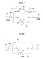
- Fig. 17 illustrates the configuration where a managing/controlling optical signal processing apparatus 90 for another wavelength band is placed in addition to the conventional arrangement for an optical transmission, so as to expand its function.
- the lights 1550 nm and 1310 nm in wavelength, which flow through the optical transmission line, are demultiplexed.
- An optical amplifier 50 then amplifies the light 1550 nm in wavelength.
- the light 1310 nm in wavelength is information-processed by the managing/controlling optical signal processing apparatus 90, and then multiplexed and output to an optical transmission line 120.
- another wavelength band of light can also be assigned by connecting optical transmission lines 113 and 114 to the optical transmission line 121.
- An optical band-pass filter can be used in place of the fiber Bragg grating as shown in Figs. 15, 16, and 17.
- a multi-layered dielectric optical filter, a Fabry-Perot optical filter, etc. can be used as the optical filter.
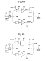
- Fig. 18 illustrates the configuration of a relaying optical amplifier, according to the tenth embodiment of the present invention.
- a light 1550 nm in wavelength is transmitted to an optical transmission line 110.
- the transmitted light is demultiplexed by an optical power divider 350, which is connected to the optical transmission line 110.
- a wavelength filter 401 has a property passing through only a light 1550 nm in wavelength. Conversely, the other wavelengths of light are absorbed. Therefore, the light 1550 nm in wavelength enters an optical amplifier 50 and is then amplified. Thereafter, it enters an optical power divider 351, connected to the optical transmission line 122, and is then output to an optical transmission line 120. Therefore, another wavelength band of light can be assigned to the optical transmission line 121.
- Fig. 19 illustrates the configuration where an optical amplifier 56 for a wavelength band of 1580 nm is placed in addition to the conventional arrangement for the wavelength band of 1550 nm, so as to increase the transmission capacity. This arrangement allows an expansion of the wavelength band.
- Lights 1550 nm and 1580 nm in wavelength, which are transmitted through the optical transmission line, are demultiplexed, amplified by the respective optical amplifiers corresponding to these wavelength bands, and then multiplexed and output to the optical transmission line 120.
- Another wavelength band of light can also be assigned by connecting optical transmission lines 113 and 114 to the optical transmission line 121.
- Fig. 20 illustrates the configuration where a managing/controlling optical signal processing apparatus 90 for another wavelength band is placed in addition to the conventional arrangement for an optical transmission, so as to expand its function.
- the lights 1550 nm and 1310 nm in wavelength, which flow through the optical transmission line, are demultiplexed.
- An optical amplifier 50 then amplifies the light 1550 nm in wavelength.
- the light 1310 nm in wavelength is information-processed by the managing/controlling optical signal processing apparatus 90. and then multiplexed and output to an optical transmission line 120.
- another wavelength band of light can also be assigned by connecting optical transmission lines 113 and 114 to the optical transmission line 121.
- optical node such as an optical demultiplexer or an optical cross-connector can be used in place of the optical amplifier.
- the optical node is comprised of optical devices, such as a WDM optical multiplexer/ demultiplexer, an optical amplifier, a wavelength light source, etc., which are dependent upon wavelengths of light. Therefore, when it is necessary to expand the wavelength band, an additional optical node has to be placed in the same manner as the optical amplifier.
- Fig. 21 illustrates the arrangement of an optical network apparatus, according to the present invention. This arrangement is made by using the configuration of the seventh embodiment, namely by adding an optical node corresponding to a new wavelength band of 1580 nm to the conventional optical node corresponding to the wavelength band of 1550 nm.
- Fig. 22 illustrates the arrangement of an optical network apparatus, according to the present invention. This arrangement is made by using the configuration of the eighth embodiment, namely by adding an optical node corresponding to a new wavelength band of 1580 nm to the conventional optical node corresponding to the wavelength band of 1550 nm.
- Fig. 23 illustrates the arrangement of an optical network apparatus, according to the present invention. This arrangement is made by using the configuration of the ninth embodiment, namely by adding an optical node corresponding to a new wavelength band of 1580 nm to the conventional optical node corresponding to the wavelength band of 1550 nm.
- Fig. 24 illustrates the arrangement of an optical network apparatus, according to the present invention. This arrangement is made by using the configuration of the tenth embodiment, namely by adding an optical node corresponding to a new wavelength band of 1580 nm to the conventional optical node corresponding to the wavelength band of 1550 nm.
- wavelength band of light can be assigned to any one of the above arrangements by connecting the optical transmission lines 113 and 114.
- the seventh to the eleventh embodiment have the following advantages.
- the expansion of the transmission band by placing an optical amplifier for a wavelength band of 1580 nm allows the transmission capacity to nearly double the conventional capacity.
- This upgrading work can be done only by adding an optical amplifier for a to-be-added wavelength band, to the optical amplifier as shown in Figs. 9, 12, 15, and 18, without halting the conventional services using the wavelength band of 1550 nm.
- an expansion to another wavelength band of, for example, 1300 nm can also be done in the same manner, using the optical transmission lines 113 and 114 as described in Figs. 10, 13, 16, and 19. This allows several transmission wavelength bands to be parallel, without halting the current services.
- placing a managing/controlling optical signal processing apparatus 90 can provide expanded services. This placement can be done only by adding the managing/controlling optical signal processing apparatus 90 for a to-be-added wavelength band, to the optical amplifier in Figs. 9, 12, 15, and 18. This can be also done without halting the conventional services using the wavelength band of 1550 nm.
- the placement of a fiber Bragg grating and wavelength filter causes a limitation in the to-be-passed wavelength band. This allows the removal of unnecessary wavelengths of light such as spontaneous emission light noises from the optical amplifier. Therefore, an optical transmission with a low degradation of reception sensitivity is possible.
- the number of WDM lights, which are transmitted through each optical transmission line is not limited to one wavelength of light. It can optionally be set to any desired number of lights, such as two, four, eight, sixteen, thirty-two, sixty-four, etc.
- the wavelength band of an input light is not limited to 1550 nm or 1580 nm. It can optionally be set to any desired wavelength band, such as 1300 nm.
- the optical multiplexer/ demultiplexer as described above, before or after the optical amplifier or the optical node, another wavelength than those handled by these apparatus can be extracted without influencing the conventional services.
- This allows an increase in the wavelength bands as well as the number of WDM lights for increasing the transmission capacity; a placement of a managing/controlling optical signal processing apparatus using another wavelength; and a placement of an optical node for an increase in the wavelength band. That is, these upgrading procedures can be smoothly performed without halting the conventional services.
- an optical filter which passes through and outputs only a wavelength of an optical signal, is provided, unnecessary wavelengths of lights such as spontaneous emission lights from the optical amplifier are eliminated. The noises caused by the spontaneous emission lights are also eliminated. Therefore, an optical transmission with a low degradation of reception sensitivity is possible.
Applications Claiming Priority (2)
| Application Number | Priority Date | Filing Date | Title |
|---|---|---|---|
| JP10292552A JP2000124855A (ja) | 1998-10-14 | 1998-10-14 | 光分波器および光合波器および光信号中継増幅装置及び光ネットワーク装置 |
| JP29255298 | 1998-10-14 |
Publications (2)
| Publication Number | Publication Date |
|---|---|
| EP0994595A2 true EP0994595A2 (de) | 2000-04-19 |
| EP0994595A3 EP0994595A3 (de) | 2005-07-06 |
Family
ID=17783251
Family Applications (1)
| Application Number | Title | Priority Date | Filing Date |
|---|---|---|---|
| EP99402500A Withdrawn EP0994595A3 (de) | 1998-10-14 | 1999-10-12 | Wellenlängemultiplexer/-demultiplexer und optisches Übertragungssystem |
Country Status (3)
| Country | Link |
|---|---|
| EP (1) | EP0994595A3 (de) |
| JP (1) | JP2000124855A (de) |
| CN (1) | CN1250988A (de) |
Cited By (3)
| Publication number | Priority date | Publication date | Assignee | Title |
|---|---|---|---|---|
| WO2001061391A2 (en) * | 2000-02-16 | 2001-08-23 | Adc Telecommunications, Inc. | Fiber optic device operating at two or more wavelengths |
| US6532321B1 (en) | 2000-02-16 | 2003-03-11 | Adc Telecommunications, Inc. | Fiber optic isolator for use with multiple-wavelength optical signals |
| US6587241B1 (en) | 1999-08-20 | 2003-07-01 | Corvis Corporation | Optical protection methods, systems, and apparatuses |
Families Citing this family (2)
| Publication number | Priority date | Publication date | Assignee | Title |
|---|---|---|---|---|
| CN102062648A (zh) * | 2010-11-11 | 2011-05-18 | 金海新源电气江苏有限公司 | 一种用于分布式光纤温度传感器的波分复用器件 |
| CN102565952B (zh) * | 2012-01-31 | 2014-05-14 | 武汉理工大学 | 全双工三端子上下载波分复用器 |
Citations (3)
| Publication number | Priority date | Publication date | Assignee | Title |
|---|---|---|---|---|
| WO1997006617A1 (en) * | 1995-08-04 | 1997-02-20 | Alcatel Alsthom Compagnie Generale D'electricite | Signal routing for fibre optic networks |
| US5696615A (en) * | 1995-11-13 | 1997-12-09 | Ciena Corporation | Wavelength division multiplexed optical communication systems employing uniform gain optical amplifiers |
| WO1998009396A1 (en) * | 1996-08-29 | 1998-03-05 | Corning Incorporated | Switchable wavelength add/drop component |
-
1998
- 1998-10-14 JP JP10292552A patent/JP2000124855A/ja active Pending
-
1999
- 1999-10-12 EP EP99402500A patent/EP0994595A3/de not_active Withdrawn
- 1999-10-13 CN CN 99121672 patent/CN1250988A/zh active Pending
Patent Citations (3)
| Publication number | Priority date | Publication date | Assignee | Title |
|---|---|---|---|---|
| WO1997006617A1 (en) * | 1995-08-04 | 1997-02-20 | Alcatel Alsthom Compagnie Generale D'electricite | Signal routing for fibre optic networks |
| US5696615A (en) * | 1995-11-13 | 1997-12-09 | Ciena Corporation | Wavelength division multiplexed optical communication systems employing uniform gain optical amplifiers |
| WO1998009396A1 (en) * | 1996-08-29 | 1998-03-05 | Corning Incorporated | Switchable wavelength add/drop component |
Cited By (6)
| Publication number | Priority date | Publication date | Assignee | Title |
|---|---|---|---|---|
| US6587241B1 (en) | 1999-08-20 | 2003-07-01 | Corvis Corporation | Optical protection methods, systems, and apparatuses |
| WO2001061391A2 (en) * | 2000-02-16 | 2001-08-23 | Adc Telecommunications, Inc. | Fiber optic device operating at two or more wavelengths |
| WO2001061391A3 (en) * | 2000-02-16 | 2002-05-02 | Adc Telecommunications Inc | Fiber optic device operating at two or more wavelengths |
| US6532321B1 (en) | 2000-02-16 | 2003-03-11 | Adc Telecommunications, Inc. | Fiber optic isolator for use with multiple-wavelength optical signals |
| US6567578B1 (en) | 2000-02-16 | 2003-05-20 | Adc Telecommunications | Fiber optic device operating at two or more wavelengths |
| US6760160B2 (en) | 2000-02-16 | 2004-07-06 | Adc Telecommunications, Inc. | Fiber optic isolator for use with multiple-wavelength optical signals |
Also Published As
| Publication number | Publication date |
|---|---|
| EP0994595A3 (de) | 2005-07-06 |
| JP2000124855A (ja) | 2000-04-28 |
| CN1250988A (zh) | 2000-04-19 |
Similar Documents
| Publication | Publication Date | Title |
|---|---|---|
| EP1583269A2 (de) | Grobes WDM optisches Übertragungssystem und -methode | |
| US6411407B1 (en) | Method for providing a bidirectional optical supervisory channel | |
| KR100334432B1 (ko) | 하나의도파관열격자다중화기를이용한양방향애드/드롭광증폭기모듈 | |
| EP1024541A2 (de) | Lichtquelle zur Ausstrahlung von Licht verschiedener Wellenlängen und zugehörige optische Übertragungsvorrichtung | |
| JPH10145298A (ja) | 波長多重通信用光分波装置 | |
| US6771854B2 (en) | Optical transmission system and optical coupler/branching filter | |
| EP1065811B1 (de) | Optische Verstärker | |
| EP1081880B1 (de) | Wdm übertragungszwischenverstärker, wdm übertragungssystem und wdm übertragungsverfahren | |
| EP0994595A2 (de) | Wellenlängemultiplexer/-demultiplexer und optisches Übertragungssystem | |
| US6313933B1 (en) | Bidirectional wavelength division multiplex transmission apparatus | |
| CA2264421A1 (en) | Optical fiber amplifier and optical amplification device for bidirectional optical transmission using the optical fiber amplifier | |
| US11582539B2 (en) | Method and apparatus for management of a spectral capacity of a wavelength division multiplexing system | |
| JP3967198B2 (ja) | 伝送装置及び伝送システム及び伝送方法及び伝送プログラム及び伝送プログラムを記録したコンピュータ読み取り可能な記録媒体 | |
| JPH10322313A (ja) | 波長多重伝送装置 | |
| EP0967752A2 (de) | WDM Nachrichtenübertragungssystem | |
| JP3233269B2 (ja) | 四光波混合抑圧方式 | |
| JP3275855B2 (ja) | 波長多重光送信装置とこの装置を備えた波長多重光伝送装置 | |
| US7236703B1 (en) | Optical wavelength division multiplexing device | |
| KR100434454B1 (ko) | 데이지 체인 파장 분할 다중화 디바이스와 이를 사용한데이지 체인 파장 분할 다중화 시스템 및 전송 네트워크 | |
| JP3039430B2 (ja) | 光分岐挿入回路及び光伝送方法 | |
| JP7428234B2 (ja) | スペクトラム監視装置、海底機器及び光通信システム | |
| JP3149915B2 (ja) | 波長多重光監視方式および波長多重光監視装置 | |
| JPH08125635A (ja) | 波長多重光伝送システム |
Legal Events
| Date | Code | Title | Description |
|---|---|---|---|
| PUAI | Public reference made under article 153(3) epc to a published international application that has entered the european phase |
Free format text: ORIGINAL CODE: 0009012 |
|
| AK | Designated contracting states |
Kind code of ref document: A2 Designated state(s): AT BE CH CY DE DK ES FI FR GB GR IE IT LI LU MC NL PT SE |
|
| AX | Request for extension of the european patent |
Free format text: AL;LT;LV;MK;RO;SI |
|
| PUAL | Search report despatched |
Free format text: ORIGINAL CODE: 0009013 |
|
| AK | Designated contracting states |
Kind code of ref document: A3 Designated state(s): AT BE CH CY DE DK ES FI FR GB GR IE IT LI LU MC NL PT SE |
|
| AX | Request for extension of the european patent |
Extension state: AL LT LV MK RO SI |
|
| AKX | Designation fees paid | ||
| REG | Reference to a national code |
Ref country code: DE Ref legal event code: 8566 |
|
| STAA | Information on the status of an ep patent application or granted ep patent |
Free format text: STATUS: THE APPLICATION IS DEEMED TO BE WITHDRAWN |
|
| 18D | Application deemed to be withdrawn |
Effective date: 20060107 |