EP1583269A2 - Grobes WDM optisches Übertragungssystem und -methode - Google Patents
Grobes WDM optisches Übertragungssystem und -methode Download PDFInfo
- Publication number
- EP1583269A2 EP1583269A2 EP05001595A EP05001595A EP1583269A2 EP 1583269 A2 EP1583269 A2 EP 1583269A2 EP 05001595 A EP05001595 A EP 05001595A EP 05001595 A EP05001595 A EP 05001595A EP 1583269 A2 EP1583269 A2 EP 1583269A2
- Authority
- EP
- European Patent Office
- Prior art keywords
- optical
- wavelength
- additional
- optical signals
- wavelength division
- Prior art date
- Legal status (The legal status is an assumption and is not a legal conclusion. Google has not performed a legal analysis and makes no representation as to the accuracy of the status listed.)
- Withdrawn
Links
Images


Classifications
-
- H—ELECTRICITY
- H04—ELECTRIC COMMUNICATION TECHNIQUE
- H04J—MULTIPLEX COMMUNICATION
- H04J14/00—Optical multiplex systems
- H04J14/02—Wavelength-division multiplex systems
-
- H—ELECTRICITY
- H04—ELECTRIC COMMUNICATION TECHNIQUE
- H04B—TRANSMISSION
- H04B10/00—Transmission systems employing electromagnetic waves other than radio-waves, e.g. infrared, visible or ultraviolet light, or employing corpuscular radiation, e.g. quantum communication
- H04B10/25—Arrangements specific to fibre transmission
- H04B10/2581—Multimode transmission
-
- H—ELECTRICITY
- H04—ELECTRIC COMMUNICATION TECHNIQUE
- H04J—MULTIPLEX COMMUNICATION
- H04J14/00—Optical multiplex systems
-
- H—ELECTRICITY
- H04—ELECTRIC COMMUNICATION TECHNIQUE
- H04J—MULTIPLEX COMMUNICATION
- H04J14/00—Optical multiplex systems
- H04J14/02—Wavelength-division multiplex systems
- H04J14/0221—Power control, e.g. to keep the total optical power constant
- H04J14/02216—Power control, e.g. to keep the total optical power constant by gain equalization
-
- H—ELECTRICITY
- H04—ELECTRIC COMMUNICATION TECHNIQUE
- H04J—MULTIPLEX COMMUNICATION
- H04J14/00—Optical multiplex systems
- H04J14/02—Wavelength-division multiplex systems
- H04J14/0224—Irregular wavelength spacing, e.g. to accommodate interference to all wavelengths
Definitions
- the present invention relates to an optical transmission system and an optical transmission method, for transmitting a wavelength division multiplexed light containing a plurality of optical signals of different wavelengths, by the use of an optical fiber, and in particular, relates to technology for adding optical signals in a coarse wavelength division multiplexing system.
- DWDM dense wavelength division multiplexing
- CWDM coarse wavelength division multiplexing
- the CWDM system is capable to hold not only optical signals in conformity with Synchronous Digital Hierarchy (SDH) being the international standard for a high-speed digital communication system using an optical fiber, but also optical signals used in an Ethernet data communication.
- SDH Synchronous Digital Hierarchy
- a technology for enabling the number of signals to be added up to 8 or more channels in the existing CWDM system is necessary.
- the present invention has been accomplished in view of the above problem and has an object of providing a CWDM optical transmission system and a CWDM optical transmission method, capable of realizing at low-cost an increase of the number of optical signals in a CWDM system by utilizing an optical transmission apparatus used in a DWDM system, and at the same time, avoiding the reduction in transmission quality.
- a CWDM optical transmission system of the present invention comprises: an optical transmission terminal including a plurality of first optical transmitters which generate a plurality of optical signals arranged on a first wavelength grid corresponding to a CWDM system and a first multiplexer which multiplexes the optical signals output from the first optical transmitters to send out a CWDM light to a transmission path; and an optical reception terminal including a first demultiplexer which demultiplexes the CWDM light transmitted from the optical transmission terminal via the transmission path and a plurality of first optical receivers which receive optical signals of respective wavelengths output from the first demultiplexer.
- at least one wavelength on the first wavelength grid is set as an additional wavelength.
- the optical transmission terminal in place of the first optical transmitter corresponding to the additional wavelength, is provided with an additional light transmission unit including; a plurality of second optical transmitters which generate a plurality of optical signals arranged within a passband including the additional wavelength of the first multiplexer, on a second wavelength grid corresponding to a DWDM system, and a second multiplexer which multiplexes optical signals output from the second optical transmitters to output a DWDM light to the first multiplexer, and also provided with an optical attenuator which attenuates the DWDM light output from the additional light transmission unit so that the total power of the DWDM light sent out from the additional light transmission unit via the first multiplexer to the transmission path is approximately equal to the power per one wavelength of the optical signals, which are output from the first optical transmitters, corresponding to wavelengths other than the additional wavelength.
- an additional light transmission unit including; a plurality of second optical transmitters which generate a plurality of optical signals arranged within a passband including the additional wavelength of the first multiplexer, on
- the optical reception terminal in place of the first optical receiver corresponding to the additional wavelength, is provided with an additional light reception unit including; a second demultiplexer which demultiplexes the DWDM light output from the first demultiplexer, and a plurality of second optical receivers which receive optical signals of respective wavelengths output from the second demultiplexer, and also provided with an optical amplifier which amplifies the DWDM light output from the first demultiplexer at a gain according to an attenuation amount of the optical attenuator.
- an additional light reception unit including; a second demultiplexer which demultiplexes the DWDM light output from the first demultiplexer, and a plurality of second optical receivers which receive optical signals of respective wavelengths output from the second demultiplexer, and also provided with an optical amplifier which amplifies the DWDM light output from the first demultiplexer at a gain according to an attenuation amount of the optical attenuator.
- the DWDM light output from the additional light transmission unit is given to the first multiplexer, and this DWDM light is multiplexed with the CWDM light of the wavelengths other than the additional wavelength, to be sent out to the transmission path. Since the total power of the DWDM light sent out to the transmission path at this time is attenuated by the optical attenuator so as to be approximately equal to the power per one wavelength of the CWDM light, the CWDM light and the added DWDM light are transmitted up to the optical reception terminal without an occurrence of nonlinear effect in the transmission path.
- the light output from the transmission path is demultiplexed by the first demultiplexer, and the optical signals of respective wavelengths corresponding to the CWDM system are received by the first optical receivers, respectively, and the DWDM light corresponding to the additional wavelength is sent to the optical amplifier to be amplified at the gain according to the attenuation amount in the optical attenuator on the optical transmission terminal side.
- the DWDM light output from the optical amplifier is demultiplexed in the second demultiplexer in the additional light reception unit, and then, the optical signals of respective wavelengths are received by the second optical receivers, respectively.
- the optical transmission terminal in place of the first optical transmitter corresponding to the additional wavelength, is provided with an additional light transmission unit including; a plurality of second optical transmitters which generate optical signals of 3 or 4 waves arranged at uneven intervals within a passband including the additional wavelength of the first multiplexer, on a second wavelength grid corresponding to a DWDM system, and a second multiplexer which multiplexes optical signals output from the second optical transmitters to output a DWDM light to the first multiplexer.
- the optical reception terminal in place of the first optical receiver corresponding to the additional wavelength, is provided with an additional light reception unit including; a second demultiplexer which demultiplexes the DWDM light output from the first demultiplexer, and a plurality of second optical receivers which receive optical signals of respective wavelengths output from the second demultiplexer.
- the optical signals of 3 or 4 waves arranged at uneven intervals on the second wavelength grid corresponding to the DWDM system are output from the additional light transmission unit, and this DWDM light is given to the first multiplexer and multiplexed with the CWDM light of the wavelengths other than the additional wavelength, to be sent out to the transmission path.
- the DWDM light sent out to the transmission path at this time is set so that the signals thereof are arranged at uneven intervals, even if the four wave mixing (FWM) being one of no-linear effects occurs in the transmission path, a frequency (wavelength) of an idler light due to the FWM does not overlap with a frequency (wavelength) of the DWDM light. Therefore, the CWDM light and the added DWDM light are transmitted up to the optical reception terminal without an occurrence of crosstalk between the DWDM light and the idler light due to the FWM.
- FWM four wave mixing
- the light output from the transmission path is demultiplexed by the first demultiplexer, and the optical signals of respective wavelengths corresponding to the CWDM system are received by the first optical receivers, respectively, and the DWDM light corresponding to the additional wavelength is demultiplexed in the second demultiplexer in the additional light reception unit, and then, the optical signals of respective wavelengths are received by the second optical receivers, respectively.
- the addition of optical signals in the CWDM system can be realized at a low-cost utilizing an optical transmission apparatus used in the DWDM system, while avoiding the reduction in transmission quality due to the nonlinear effect in the transmission path. As a result, it becomes possible to add the optical signals so as to exceed the maximum number of signals in the CWDM system.
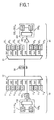
- FIG. 1 is a diagram showing a configuration of a CWDM optical transmission system according to a first embodiment of the present invention.
- the CWDM optical transmission system of the present embodiment comprises, for example, an optical transmission terminal 10, and an optical reception terminal 20 connected to the optical transmission terminal 10 via a transmission path 30.
- the optical transmission terminal 10 includes: for example, optical transmitters (E/O) 11 1 through 11 4 , and 11 6 through 11 8 generating optical signals CH1 through CH4, and CH6 through CH8 among a plurality (8 waves in this case) of optical signals CH1 through CH8 arranged on a wavelength grid having 20nm inter-wavelength corresponding to CWDM; a multiplexer 12 having 8 input ports corresponding to the optical signals CH1 through CH8 and one output port; an additional light transmission unit 100 5 which generates a DWDM light as an additional light in place of the optical signal CH5; and a variable optical attenuator (VOA) 101 5 inserted between an output port of the additional light transmission unit 100 5 and the input port, which corresponds to the optical signal CH5, of the multiplexer 12.
- E/O optical transmitters
- VOA variable optical attenuator
- the respective optical transmitters 11 1 through 11 4 , and 11 6 through 11 8 are the same as optical transmitters used in a conventional CWDM system.
- a wavelength of the optical signal CH1 output from the optical transmitter 11 1 is set to 1470nm
- a wavelength of the optical signal CH2 output from the optical transmitter 11 2 is set to 1490nm
- a wavelength of the optical signal CH3 output from the optical transmitter 11 3 is set to 1510nm
- a wavelength of the optical signal CH4 output from the optical transmitter 11 4 is set to 1530nm
- a wavelength of the optical signal CH6 output from the optical transmitter 11 6 is set to 1570nm
- a wavelength of the optical signal CH7 output from the optical transmitter 11 7 is set to 1590nm
- a wavelength of the optical signal CH8 output from the optical transmitter 11 8 is set to 1610nm.
- a wavelength of the optical signal CH5 to be an additional wavelength in the present embodiment is set to 1550nm. Furthermore, the optical signal power output from each of the optical transmitters 11 1 through 11 4 , and 11 6 through 11 8 is, as described later, previously adjusted to a required level at which a nonlinear effect does not occur in the transmission path 30.
- the multiplexer 12 multiplexes the optical signals given to the input ports corresponding to the optical signals CH1 through CH8, and sends the multiplexed light to the transmission path 30 via one output port. A transmission characteristic of this multiplexer 12 will be described later.
- the additional light transmission unit 100 5 comprises, for example, optical transmitters (E/O) 111 1 through 111 16 generating a plurality (16 waves in this case, as described later) of optical signals arranged on a wavelength grid having 0.8nm inter-wavelength, and a multiplexer 112 having 16 input ports corresponding to the optical signals output from the optical transmitters 111 1 through 111 16 , and one output port.
- optical transmitters (E/O) 111 1 through 111 16 generating a plurality (16 waves in this case, as described later) of optical signals arranged on a wavelength grid having 0.8nm inter-wavelength
- a multiplexer 112 having 16 input ports corresponding to the optical signals output from the optical transmitters 111 1 through 111 16 , and one output port.
- the optical transmitters 111 1 through 111 16 are the same as optical transmitters used in the existing DWDM systems. Wavelengths of the optical signals output from the optical transmitters 111 1 through 111 16 , are, as described later, set to be within a passband of the input port, which corresponds to the optical signal CH5, of the multiplexer 12.
- the multiplexer 112 multiplexes the optical signals output from the optical transmitters 111 1 through 111 16 to generate a DWDM light, and outputs the DWDM light to the variable optical attenuator 101 5 as an additional light, in place of the optical signal CH5.
- the variable optical attenuator 101 5 is a well-known optical attenuator for variably changing an attenuation amount of input light.
- the attenuation amount of this variable optical attenuator 101 5 is, as described in detail later, either previously set or is controlled in accordance with a control signal given from the outside or the like (not shown in figure), so that the total power of the DWDM light sent out from the multiplexer 12 to the transmission path 30 is approximately equal to the power per one wavelength of the optical signals CH1 through CH4, and CH6 through CH8.
- the optical reception terminal 20 includes, for example, a demultiplexer 21 having one input port connected to the transmission path 30 and 8 output ports corresponding to the optical signals CH1 through CH8 arranged on the wavelength grid corresponding to CWDM, optical receivers (O/E) 22 1 through 22 4 , and 22 6 through 22 8 receiving optical signals output from the output ports corresponding to the optical signals CH1 through CH4, and CH6 through CH8 in the demultiplexer 21, an optical amplifier 201 5 connected to the output port, which corresponds to the optical signal CH5, of the demultiplexer 21, and an additional light reception unit 200 5 receiving the DWDM light output from the optical amplifier 201 5 .
- a demultiplexer 21 having one input port connected to the transmission path 30 and 8 output ports corresponding to the optical signals CH1 through CH8 arranged on the wavelength grid corresponding to CWDM
- optical receivers (O/E) 22 1 through 22 4 , and 22 6 through 22 8 receiving optical signals output from the output ports corresponding to the optical signals CH1 through CH4, and CH6 through CH8
- the demultiplexer 21 demultiplexes the wavelength division multiplexed light propagated through the transmission path 30 to be given to the input port thereof, according to a passband corresponding to the optical signals CH1 through CH8, and outputs the respective demultiplexed lights from the corresponding output ports thereof.
- a transmission characteristic for the wavelength of the multiplexer 12 will be described later.
- the optical receivers 22 1 through 22 4 , and 22 6 through 22 8 which are the same as optical receivers used in a conventional CWDM system, receive optical signals output from the output ports corresponding to the optical signals CH1 through CH4, and CH6 through CH8 in the demultiplexer 21, to perform the data identification processing and the like.
- the optical amplifier 201 5 is a typical optical amplifier, which amplifies the DWDM light output from the output port, which corresponds to the optical signal CH5, of the demultiplexer 21, at the gain according to the attenuation amount of the variable optical attenuator 101 5 of the optical transmission terminal 10. Note, it is preferable that this optical amplifier 201 5 is subjected to an automatic gain control (AGC) or an automatic level control (ALC).
- AGC automatic gain control
- ALC automatic level control
- the additional light reception unit 200 5 includes, for example, a demultiplexer 221 having one input port connected to an output port of the optical amplifier 201 5 and 16 output ports corresponding to a wavelength grid corresponding to DWDM, and optical receivers (O/E) 222 1 through 222 16 receiving optical signals from the respective output ports of the demultiplexer 221.
- the demultiplexer 221 demultiplexes the DWDM light output from the demultiplexer 21 via the optical amplifier 201 5 to be given to the input port thereof, and outputs the optical signals from the corresponding output ports.
- the optical receivers 222 1 through 222 16 which are the same as the optical receivers used in the existing DWDM system, receive optical signals output from the output ports of the demultiplexer 221, to perform the data identification processing and the like.
- a typical 1.3 ⁇ m zero-dispersion single mode fiber (SMF) is used for the transmission path 30.
- optical signal wavelength allocation in the present CWDM optical transmission system and the number of optical signals corresponding to DWDM, which are capable to be added, are described.
- FIG. 2 shows an example of a typical CWDM/DWDM signal wavelength allocation.
- the inter-wavelength is regulated to 20nm, and a plurality of optical signals are arranged within a wide wavelength band over the S-band indicating the wavelength band of 1450nm through 1530nm, the C-band indicating the wavelength band of 1530nm through 1565nm, and the L-band indicating the wavelength band of 1565nm through 1625nm.
- optical signals of the wavelengths 1470nm, 1490nm, 1510nm, 1530nm, 1550nm, 1570nm, 1590nm, and 1610nm are arranged.
- the optical signals CH1 through CH8 of 8 waves are set to correspond to the above described wavelengths, beginning from the short wavelength side.
- the inter-wavelength is regulated to 0.8nm (100GHz) or 0.4nm (50GHz) or the like, and a plurality of optical signals are arranged to correspond to the C-band or the L-band, and various types of optical transmission apparatuses for the C-band or the L-band are in practical use.
- the number of DWDM light wavelengths capable to be added is determined according to passbands of the transmission side multiplexer 12 and the reception side demultiplexer 21, which are used in the CWDM optical transmission system. That is to say, as shown in FIG. 3, for example, the above multiplexer 12 and the demultiplexer 21 have the passbands respectively corresponding to the wavelengths of the optical signals for CWDM, and the width of each passband is, for example, approximately 13.0nm.
- the wavelengths thereof can be set as the additional wavelengths. If the optical signal CH5 is set as an additional wavelength, the entire passband, which includes that additional wavelength, of the multiplexer/demultiplexer, is within a signal band of the C-band optical transmission apparatus, and therefore, it is possible to add the optical signals corresponding to DWDM up to 16 waves.
- optical signal CH4 is set as an additional wavelength, approximately half of the passband, which includes that additional wavelength, of the multiplexer/demultiplexer is within the signal band of the C-band optical transmission apparatus, and therefore, it is possible to add the optical signals corresponding to DWDM up to 8 waves.
- both the above optical signals CH4 and CH5 are set as the additional wavelengths, it becomes possible to add a maximum of 24 waves.
- the wavelengths thereof can be set as the additional wavelengths. If the optical signal CH7 is set as the additional wavelength, the entire passband, which includes that additional wavelength, of the multiplexer/demultiplexer is within a signal band of the L-band optical transmission apparatus, and therefore, it is possible to add the optical signals corresponding to DWDM up to 16 waves.
- optical signal CH6 or CH8 is set as the additional wavelength, approximately half of the passband, which includes that additional wavelength, of the multiplexer/demultiplexer is within the signal band of the L-band optical transmission apparatus, and therefore, it is possible to add the optical signals corresponding to DWDM up to 8 waves.
- the above optical signals CH6, CH7 and CH8 are all set as the additional wavelengths, it is possible to add the optical signals of 32 waves at a maximum.
- the existing C-band and L-band optical transmission apparatuses may be combined with each other, and then, it is possible to further add the many optical signal wavelengths.
- the inter-wavelength of the optical signals corresponding to DWDM is set to 0.4nm (50GHz), the signals capable to be added can be set to twice the above number.
- the additional light transmission unit 100 5 and the variable optical attenuator 101 5 , as well as the additional light reception unit 200 5 and the optical amplifier 201 5 can utilize the existing C-band optical transmission apparatus, and therefore, it is possible to add a maximum of 16 waves.
- the number of signals in the entire CWDM optical transmission system is 23 waves (optical signals CH1 through CH4, and CH6 through CH8, and the added DWDM light of 16 waves).
- the optical signals of 16 waves generated in the optical transmission unit used in the existing DWDM system are given to the CWDM optical transmission system, in place of the one wavelength optical signal CH5, without consideration of the light power during fiber transmission as with the conventional technology, since the total power of the DWDM light of 16 waves is much greater than the power of the optical signal CH5, there is a high possibility that the power of the light sent out to the transmission path will exceed the level at which the nonlinear effect occurs.
- variable optical attenuator 101 5 is disposed in the output stage of the additional light transmission unit 100 5 , and the attenuation amount of the variable optical attenuator 101 5 is adjusted so that the total power of the DWDM light sent out to the transmission path 30 from the multiplexer 12 is approximately equal to the power per one wavelength of the optical signals CH1 through CH4, and CH6 through CH8 corresponding to CWDM.
- FIG. 4 is a diagram showing an example of the power of each optical signal during transmission in the first embodiment.
- the attenuation amount of the variable optical attenuator 101 5 is adjusted so that the power per one wavelength of the DWDM light of 16 waves becomes -10dBm/ch.
- the total power of the light sent out from the multiplexer 12 to the transmission path 30 is of the same level as that when only the optical signals CH1 through CH8 corresponding to CWDM are multiplexed to be sent out to the transmission path 30, a situation in which the nonlinear effect occurs in the optical signals propagated through the transmission path 30 can be avoided.
- the optical amplifier 201 5 is connected to the output port, which corresponds to the additional wavelengths, of the demultiplexer 21 of the optical reception terminal 20, and the DWDM light branched by the demultiplexer 21 is amplified at the gain according to the attenuation amount of the variable optical attenuator 101 5 on the transmission end.
- the DWDM light of a maximum of 16 waves which is output from the additional light transmission unit 100 5 to be sent out to the transmission path 30 via the variable optical attenuator 101 5 and the multiplexer 12, has the power per one wavelength of -10dBm/ch, and the total power for 16 waves of +2dBm/ch.
- the SMF having the total length of 50km and a transmission loss of 20dB
- the DWDM light of 16 waves reaching the optical reception terminal 20 has the total power of -18dBm/ch and the power per one wavelength of -30dBm/ch.
- the power of the DWDM light input to the optical amplifier 201 5 is -34dB/ch per one wavelength.
- OSNR optical signal to noise ratio
- a third term is a constant corresponding to the C-band.
- the existing optical transmission apparatus used in the DWDM system is utilized without any modification, it is possible to avoid the reduction in signal quality while achieving the advantage of low-cost, thereby enabling the addition of optical signals. As a result, it becomes possible to provide, at low-cost, an optical communication service exceeding the maximum number of signals capable to be transmitted (8 waves) in the conventional CWDM system.
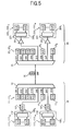
- FIG. 5 is a diagram showing a configuration of a CWDM optical transmission system of the second embodiment.
- the CWDM optical transmission system shown in FIG. 5 is configured such that, in the configuration of the first embodiment, in addition to the wavelength of the optical signal CH5, the wavelength of the optical signal CH7 is set as the additional wavelength, and the L-band optical transmission apparatus used in the existing DWDM system is also utilized to increase the number of signals capable to be added. More specifically, an additional light transmission unit 100 7 and a variable optical attenuator 101 7 are provided in the optical transmission terminal 10, in place of the optical transmitter 11 7 used in the first embodiment, and the power of a DWDM light output from the additional light transmission unit 100 7 is adjusted by the variable optical attenuator 101 7 and thereafter, given to the input port, which corresponds to the optical signal CH7, of the multiplexer 12.
- an additional light reception unit 200 7 and an optical amplifier 201 7 are provided in the optical reception terminal 20, in place of the optical transmitter 22 7 used in the first embodiment, and the DWDM light output from the output port, which corresponds to the optical signal CH7, of the demultiplexer 21 is amplified by the optical amplifier 201 7 and thereafter, given to the additional light reception unit 200 7 .
- the structures of the additional light transmission unit 100 7 and the variable optical attenuator 101 7 , and the additional light reception unit 200 7 and optical amplifier 201 7 are basically similar to the structures of the additional light reception unit 100 5 and the variable optical attenuator 101 5 , and the additional light reception unit 200 5 and the optical amplifier 201 5 , with each signal wavelength band thereof shifted from the C-band to the L-band. Therefore, the specific description thereof is omitted here.
- the optical signal CH7 positioned within the L-band is set as the additional wavelength, as in the wavelength allocation of the optical signals shown in FIG. 6, and thus, for example, the optical signals of a maximum of 16 waves can be arranged at the 0.8nm inter-wavelength within the passband corresponding to the multiplexer 12 and the demultiplexer 21 (refer to FIG. 3).
- an OSNR of the DWDM light output from the optical amplifier 201 7 in the optical reception terminal 20 is calculated based on the following equation.
- a third term is a constant corresponding to the L-band.
- the optical signals of a maximum of 32 waves can be added by utilizing the C-band and L-band optical transmission apparatuses used in the existing DWDM system, and therefore, it becomes possible to add the number of signals in the entire CWDM optical transmission system up to a maximum of 38 waves by combining the optical signals CH1 through CH4, CH6 and CH8 with the added DWDM light of 32 waves.
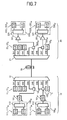
- FIG. 7 is a diagram showing a configuration of a CWDM optical transmission system of the third embodiment.
- the CWDM optical transmission system shown in FIG. 7 is configured such that, in the configuration of the second embodiment, in addition to the wavelengths of the optical signals CH5 and CH7, the wavelengths of the optical signals CH4 and CH6 are also set as the additional wavelengths, and the C-band and L-band optical transmission apparatuses used in the existing DWDM system are also utilized to further increase the number of signals capable to be added.
- an additional light transmission unit 100 45 which generates a DWDM light as the additional light in place of the optical signals CH4 and CH5, a variable optical attenuator 101 45 which adjusts the total power of the DWDM light, and a demultiplexer 102 45 which demultiplexes the DWDM light passed through the variable optical attenuator 101 45 into a component corresponding to the optical signal CH4 and a component corresponding to the optical signal CH5, to output these components to the respective input port of the multiplexer 12.
- an additional light transmission unit 100 67 which generates a DWDM light as the additional light in place of the optical signals CH6 and CH7, a variable optical attenuator 101 67 which adjusts the total power of the DWDM light, and a demultiplexer 102 67 which demultiplexes the DWDM light passed through the variable optical attenuator 101 67 into a component corresponding to the optical signal CH6 and a component corresponding to the optical signal CH7, to output these components to the respective input port of the multiplexer 12.
- a multiplexer 202 45 which multiplexes DWDM lights output from the output ports, which correspond to the optical signals CH4 and CH5, of the demultiplexer 21, an optical amplifier 201 45 which amplifies the DWDM light output from the multiplexer 202 45 , and an additional light reception unit 200 45 which performs the reception processing of the DWDM light output from the receiving optical amplifier 201 45 .
- a multiplexer 202 67 which multiplexes DWDM lights output from the output ports, which correspond to the optical signals CH6 and CH7, of the demultiplexer 21, an optical amplifier 201 67 which amplifies the DWDM light output from the multiplexer 202 67 , and an additional light reception unit 200 67 which performs the reception processing of the DWDM light output from the optical amplifier 201 67 .
- the optical signal CH4 positioned within the C-band is set as the additional wavelength, as in the wavelength allocation of the optical signals shown in FIG. 8, and thus, for example, the optical signals of a maximum of 8 waves can be arranged at the 0.8nm inter-wavelength within the passband corresponding to the multiplexer 12 and the demultiplexer 21 (refer to FIG. 3), and the DWDM light containing the optical signals of a maximum of 24 waves can be added for the C-band in combination with the optical signals of a maximum of the 16 waves capable to be arranged within the passband corresponding to the optical signal CH5 positioned within the same C-band.
- the optical signals of a maximum of 8 waves can be arranged within the passband corresponding to the multiplexer 12 and the demultiplexer 21, and the DWDM light containing the optical signals of a maximum of 24 waves can be added for the L-band in combination with the optical signals of a maximum of 16 waves capable to be arranged within the passband corresponding to the optical signal CH7 positioned within the same L-band.
- an OSNR of approximately 19dB can be ensured for this additional light with an output of the optical amplifier 201 67 , it is possible to perform the sufficient reception processing in the additional light reception unit 200 7 .
- the optical signals of a maximum of 48 waves can be added by utilizing the C-band and L-band optical transmission apparatuses used in the existing DWDM system, and therefore, it becomes possible to increase the number of signals in the entire CWDM optical transmission system up to a maximum of 52 waves by combining the optical signals CH1 through CH3 and CH8 with the added DWDM light of 52 waves.
- the wavelengths of the optical signals CH6 and CH7 are set as the additional wavelengths for the L-band.
- the configuration has been shown in the case where the 1.3 ⁇ m zero-dispersion single mode fiber is used for the transmission path 30.
- the description is made on a case where a dispersion-shifted fiber (DSF) whose zero-dispersion wavelength is shifted to 1.5 ⁇ m is used for the transmission path 30.
- DSF dispersion-shifted fiber
- FIG. 9 is a diagram showing a configuration of a CWDM optical transmission system of the fourth embodiment.
- the optical signal CH7 is set as the additional wavelength
- the additional light transmission unit 100 7 and the variable optical attenuator 101 7 are provided in the optical transmission terminal 10
- the additional light reception unit 200 7 and the optical amplifier 201 7 are provided in the optical reception terminal 20, corresponding to the optical signal CH7.
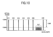
- the additional light transmission unit 100 7 and the variable optical attenuator 101 7 , and the additional light reception unit 200 7 and the optical amplifier 201 7 are the same as those used in the second embodiment, and in the case where the inter-wavelength of the optical signals corresponding to DWDM is set to, for example, 0.8nm, the optical signals of a maximum of 16 waves can be added, as shown in the optical signal wavelength allocation in FIG. 10.
- the example has been shown in which the optical signal CH7 within the L-band is set as the additional wavelength is shown.
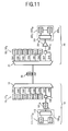
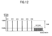
- the additional wavelength when the dispersion-shifted fiber is used is not limited to this, and it is possible to set the optical signals CH7 and CH8 as the additional wavelengths as shown in the configuration diagram in FIG. 11 and the wavelength allocation diagram in FIG. 12.
- either the optical signal CH6 or the optical signal CH8 may be set as the additional wavelength in place of the optical signal CH7, or a combination of any two or all of the optical signals CH6 through CH8 may be set as the additional wavelengths.
- the description is made on an application example to a CWDM optical transmission system in which optical signals are transmitted in bi-directions using a single-core 1.3 ⁇ m SMF.
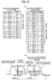
- FIG. 13 is a diagram showing a configuration of a CWDM optical transmission system of the fifth embodiment.
- the optical signals CH1 through CH8 of 8 waves on the wavelength grid corresponding to CWDM in which, among the optical signals CH1 through CH8 of 8 waves on the wavelength grid corresponding to CWDM, the optical signals CH1, CH3, CH5 and CH7 having odd-numbered wavelength numbers are transmit on the uplink, and the optical signals CH2, CH4, CH6 and CH8 having even-numbered wavelength numbers are transmit on the downlink, the optical signals CH5 and CH7 on the uplink side and the optical signals CH4 and CH6 on the downlink side are set as additional wavelengths respectively.
- an additional light transmission unit 100 i and a variable optical attenuator 101 i are respectively provided corresponding to the respective additional wavelengths.
- a multiplexer/demultiplexer 51 provided in the vicinity of one end of the transmission path 30 sends the optical signals CH1 and CH3, and the DWDM lights respectively corresponding to the optical signals CH5 and CH7, which are output from the multiplexer 12 on the uplink side, to the transmission path 30, and conversely, transmits the optical signals CH2 and CH8, and the DWDM lights corresponding to the optical signals CH4 and CH6, which have been propagated through the transmission path 30, to a demultiplexer 21' on the downlink side.
- a multiplexer/demultiplexer 52 provided in the vicinity to the other end of the transmission path 30 sends the optical signals CH2 and CH8, and the DWDM lights corresponding to the optical signals CH4 and CH6, which are output from a multiplexer 12' on the downlink side, to the transmission path 30, and conversely, transmits the optical signals CH1 and CH3, and the DWDM lights corresponding to the optical signals CH5 and CH7, which have been propagated through the transmission path 30, to the demultiplexer 21 on the uplink side.
- the DWDM light of a maximum of 32 waves can be added with the 16 waves in the C-band corresponding to the optical signal CH5, and 16 waves in the L-band corresponding to the optical signal CH7, and in the downlink, it becomes possible to add the DWDM light of a maximum of 16 waves, with 8 waves in the C-band corresponding to the optical signal CH4, and 8 waves in the L-band corresponding to the optical signal CH6.
- the optical signal CH8 is set as the additional wavelength.
- the allocation of the optical signals CH1 through CH8 of 8 waves to the uplink and downlink is not limited to the above described use of odd and even-numbered wavelengths, and may be allocated in accordance with an arbitrary rule.
- the optical signals CH6 through CH8 within the L-band are set as the additional wavelengths, considering the occurrence of four wave mixing (FWM) in the DWDM light of the C-band.
- FWM four wave mixing
- a small number of wavelengths for example, up to 4 waves
- the passband of each of the multiplexer 12 and demultiplexer 21 corresponding to CWDM is narrower than the signal interval for CWDM 20nm, that is, ⁇ 10nm, it is practically impossible to arrange optical signals on all of the points on the wavelength grid corresponding to DWDM.
- the passband of each of the multiplexer 12 and the demultiplexer 21 is ⁇ 6.5nm
- optical signals corresponding to DWDM can be arranged on 10 grids of from CH1' through CH10' and the frequency band thereof is 900GHz.
- 1550nm band corresponding to the optical signal CH5 corresponding to CWDM optical signals corresponding to DWDM can be arranged on 16 grids of from CH20' through CH35' and the frequency band thereof is 1500GHz.
- frequency points at which idler lights due to the FWM are generated including frequency points at which idler lights due to degenerate four-wave mixing are generated are shown in FIG. 16, for example.
- ⁇ f12 in the figure represents an interval between f1 and f2.
- ⁇ f23 represents an interval between f2 and f3
- ⁇ f13 represents an interval between f1 and f3.
- the respective optical signals having frequencies f1 through f3 are arranged at uneven intervals (here, 100GHz and 300GHz intervals), so that the frequencies of the optical signals do not overlap with the frequencies at which the idler lights due to the FWM are generated, and as a result, the transmission quality is not degraded due to the occurrence of crosstalk. It is understood from FIG. 16 that the frequency points at which the idler lights are generated are 9 points with regard to the optical signals of 3 waves.
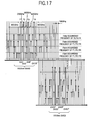
- FIG. 17 shows the consideration result.
- the arrangement intervals of optical signals of 4 waves having frequencies f1 through f4 are 200GHz, 300GHz and 400GHz, for example.
- the optical signals CH1', CH3', CH6' and CH10' each corresponding to DWDM shown in (A) of FIG. 15 are arranged.
- the arrangement intervals of the optical signals of 4 waves are 200GHz, 300GHz and 400GHz, for example.
- the optical signals CH23', CH25', CH28' and CH32' each corresponding to DWDM shown in (A) of FIG. 15 are arranged. It is understood from FIG. 17 that the frequencies of the optical signals arranged in 1550nm band do not overlap with the frequency points at which the idler lights due to the FWM are generated in 1530nm band. Further, as well as the frequency points in 1530nm band, there exist a plenty of frequency points at which the idler lights due to the FWM are generated in 1550nm band.
- these frequency points do not overlap with the frequencies of the respective optical signals CH23', CH25', CH28' and CH32'. In addition, these frequency points do not overlap with the frequencies of the optical signals CH1', CH3', CH6' and CH10' in 1530nm band.
- FIG. 18 is a diagram in which a relative relation between each optical signal arranged at uneven interval in 1530nm band and 1550nm band, and the idler light due to the FWM is processed.
- a FWM crosstalk margin width W45 indicating the spacing of from a longest wavelength among the idler lights due to the FWM caused by the optical signals in 1530nm band to a shortest wavelength among the optical signals in 1550nm band
- a FWM crosstalk margin width W54 indicating the spacing of from the shortest wavelength among the idler lights due to the FWM caused by the optical signals in 1550nm band to the longest wavelength among the optical signals in 1530nm band
- both of the FWM crosstalk margin widths W45 and W54 are 400GHz.
- FIG. 19 shows specific optical signal arrangement examples in the case where the arrangement intervals of the optical signals of 4 waves in each of 1530nm band and 1550nm band are set to 200GHz, 300GHz and 400GHz. It means that the arrangement of the optical signals of 4 waves at uneven intervals of 200GHz, 300GHz and 400GHz in the present embodiment applies the combination of signal arrangements shown in FIG. 19 is applied.
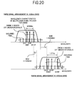
- FIG. 20 is a diagram in which a relative relation between each optical signal and the idler light due to the FWM is processed in the case where the arrangement intervals of the optical signals of 4 waves in 1530nm band are set to 200GHz, 300GHz and 400GHz, and the arrangement intervals of the optical signals of 4 waves in 1550nm band are set to 300GHz, 400GHz and 500GHz.
- the optical signals CH1', CH3', CH6' and CH10' are arranged in 1530nm band
- the optical signals CH23', CH26', CH30' and CH35' are arranged in 1550nm band.
- the FWM crosstalk margin width W45 is 400GHz and the FWM crosstalk margin width W54 is 100GHz.
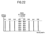
- FIG. 21 shows a system configuration example in the case where optical signals of 8 waves corresponding to DWDM are added.
- FIG. 22 is a pattern diagram showing the signal arrangement corresponding to the system configuration example in FIG. 21.
- the optical signals of 4 waves + 4 waves corresponding to DWDM to be added in place of the optical signals CH4 and CH5 corresponding to CWDM are arranged at uneven intervals as described above, and accordingly, the occurrence of crosstalk due to the FWM is avoided. Therefore, differently from the first to fifth embodiments, it is no longer necessary to attenuate the optical signals corresponding to DWDM so as to be equal to the optical signals corresponding to CWDM, to be sent to the transmission path 30.
- the configuration may be such that optical amplifiers 103 4 , 103 5 , 203 4 and 203 5 are disposed to either the optical transmission terminal 10 or the optical reception terminal 20, or to both of the optical transmission terminal 10 and the optical reception terminal 20, to set the level of added optical signals corresponding to DWDM to be equal to or higher than the level of the optical signals corresponding to CWDM.
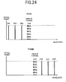
- FIG. 23 shows a configuration example of a bi-directional system in which optical signals corresponding to DWDM are added by 4 waves in each of the uplink and the downlink.
- FIG. 24 is a pattern diagram of the signal arrangement corresponding to the bi-directional system configuration example in FIG. 23.
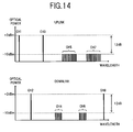
- the optical signals CH1, CH2 and CH3 corresponding to CWDM and the optical signals of 4 waves corresponding to DWDM to be added in place of the optical signal CH4 are allocated to the uplink.
- the optical signals CH6, CH7 and CH8 corresponding to CWDM and the optical signals of 4 waves corresponding to DWDM to be added in place of the optical signal CH5 are allocated to the downlink.
- a DFB-LD with an external semiconductor modulator (a DFB laser with an EA modulator) can be adopted as the optical transmitters 111 1 through 111 4 for DWDM.
- the optical transmitter using the DFB-LD with the external semiconductor modulator has advantages of low cost and miniaturization compared with the optical transmitter using a LN type external modulator.
- the inter-wavelength of the respective optical signals corresponding to DWDM to be added is at least 200GHz. Therefore, it is no longer necessary to dispose a wavelength locker which is typically used for the wavelength stabilizing control of the optical transmitter. Thus, it becomes possible to configure a system using a miniaturized optical transmitter at a lower cost.
- the optical signals of the above wavelength allocation can be sent out not only to the transmission path using the DSF but also to a transmission path using the SMF just as they are.
- the configuration in the sixth embodiment also achieves an effect of independence of the types of fiber transmission path, as the system corresponding to the addition of a small number of wavelengths of about 3 waves or 4 waves.
Landscapes
- Engineering & Computer Science (AREA)
- Computer Networks & Wireless Communication (AREA)
- Signal Processing (AREA)
- Physics & Mathematics (AREA)
- Electromagnetism (AREA)
- Optical Communication System (AREA)
Applications Claiming Priority (4)
| Application Number | Priority Date | Filing Date | Title |
|---|---|---|---|
| JP2004101764 | 2004-03-31 | ||
| JP2004101764 | 2004-03-31 | ||
| JP2004262153 | 2004-09-09 | ||
| JP2004262153 | 2004-09-09 |
Publications (2)
| Publication Number | Publication Date |
|---|---|
| EP1583269A2 true EP1583269A2 (de) | 2005-10-05 |
| EP1583269A3 EP1583269A3 (de) | 2007-07-11 |
Family
ID=34889450
Family Applications (1)
| Application Number | Title | Priority Date | Filing Date |
|---|---|---|---|
| EP05001595A Withdrawn EP1583269A3 (de) | 2004-03-31 | 2005-01-26 | Grobes WDM optisches Übertragungssystem und -methode |
Country Status (6)
| Country | Link |
|---|---|
| US (1) | US7831118B2 (de) |
| EP (1) | EP1583269A3 (de) |
| JP (1) | JP4463808B2 (de) |
| KR (1) | KR100789095B1 (de) |
| CN (1) | CN1906876B (de) |
| WO (1) | WO2005096534A1 (de) |
Cited By (1)
| Publication number | Priority date | Publication date | Assignee | Title |
|---|---|---|---|---|
| WO2008147672A1 (en) * | 2007-05-22 | 2008-12-04 | General Instrument Corporation | Method and apparatus for reducing crosstalk in a dwdm transmission system |
Families Citing this family (30)
| Publication number | Priority date | Publication date | Assignee | Title |
|---|---|---|---|---|
| JPH0736781B2 (ja) * | 1992-07-28 | 1995-04-26 | 幸男 金沢 | 支持台 |
| JP4744311B2 (ja) * | 2006-01-31 | 2011-08-10 | 富士通株式会社 | 光伝送ネットワーク |
| US7587137B2 (en) * | 2006-05-08 | 2009-09-08 | Cisco Technology, Inc. | System and method for seamless integration of CWDM and DWDM technologies on a fiber optics infrastructure |
| US8917986B2 (en) * | 2006-12-07 | 2014-12-23 | Arris Solutions, Inc. | Extended range for CWDM optical transport |
| US20090010649A1 (en) * | 2007-07-02 | 2009-01-08 | Tellabs Bedford, Inc. | Optical access network with legacy support |
| US8260138B2 (en) * | 2008-04-07 | 2012-09-04 | Arris Solutions, Inc. | Wavelength distribution for optical transport |
| JP5178544B2 (ja) * | 2009-01-16 | 2013-04-10 | 三菱電機株式会社 | 波長多重伝送システム |
| JP2010226169A (ja) * | 2009-03-19 | 2010-10-07 | Fujitsu Ltd | 光送信装置、光通信方法および光通信システム |
| JP5489533B2 (ja) * | 2009-05-20 | 2014-05-14 | 三菱電機株式会社 | 光伝送装置、光波長増設装置および光波長増設方法 |
| GB2484868B (en) * | 2009-08-18 | 2013-08-07 | Hitesh Mehta | A novel fiber optic training kit |
| JP5617503B2 (ja) | 2010-09-30 | 2014-11-05 | 富士通株式会社 | 光ネットワーク中継装置 |
| JP5807338B2 (ja) | 2011-02-14 | 2015-11-10 | 富士通株式会社 | 光伝送装置および光フィルタ回路 |
| JP5760490B2 (ja) * | 2011-02-18 | 2015-08-12 | 日本電気株式会社 | 波長分割多重システム並びにそのシステムにおける送信側波長分割多重装置及び受信側波長分割多重分離装置 |
| US10469790B2 (en) * | 2011-08-31 | 2019-11-05 | Cablecam, Llc | Control system and method for an aerially moved payload system |
| US9477141B2 (en) | 2011-08-31 | 2016-10-25 | Cablecam, Llc | Aerial movement system having multiple payloads |
| US9337949B2 (en) | 2011-08-31 | 2016-05-10 | Cablecam, Llc | Control system for an aerially moved payload |
| KR101477169B1 (ko) * | 2011-09-26 | 2014-12-29 | 주식회사 에치에프알 | 클라우드 기반 네트워크를 위한 광 선로 공유 방법과 그를 위한 시스템 및 장치 |
| US9379838B2 (en) * | 2011-12-30 | 2016-06-28 | Infinera Corporation | Optical communication system having tunable sources |
| US9485049B2 (en) * | 2013-03-29 | 2016-11-01 | Infinera Corporation | Adjusting carrier spacing in a channel |
| JP6155803B2 (ja) * | 2013-04-25 | 2017-07-05 | 日本電気株式会社 | 光波長多重通信システム、光波長多重通信方法、及び光合分波装置 |
| KR101819254B1 (ko) * | 2013-09-13 | 2018-01-17 | 한국전자통신연구원 | 대용량 광 트랜시버 모듈 |
| US9496961B2 (en) | 2015-04-09 | 2016-11-15 | International Business Machines Corporation | External cavity laser based wavelength division multiplexing superchannel transceivers |
| JP6103097B1 (ja) * | 2016-03-18 | 2017-03-29 | 日本電気株式会社 | 光伝送装置及びその制御方法 |
| CN110521142A (zh) * | 2017-04-18 | 2019-11-29 | 日本电气株式会社 | 双向光传输系统和双向光传输方法 |
| JP6988266B2 (ja) * | 2017-08-28 | 2022-01-05 | 住友電気工業株式会社 | 光送信器 |
| JP7135783B2 (ja) * | 2018-11-27 | 2022-09-13 | 富士通株式会社 | 伝送システム、伝送装置、及び伝送方法 |
| CN112399283B (zh) * | 2019-08-16 | 2021-10-26 | 中国移动通信有限公司研究院 | 一种波分复用系统、局端装置及远端装置 |
| CN112769519A (zh) * | 2019-11-04 | 2021-05-07 | 中国电信股份有限公司 | 光信号通信系统 |
| US11671177B2 (en) | 2021-02-25 | 2023-06-06 | Google Llc | 8WDM optical transceiver at 10nm wavelength grid |
| US11686900B2 (en) * | 2021-03-11 | 2023-06-27 | Taiwan Semiconductor Manufacturing Company, Ltd. | Semiconductor package, optical device and method of fabricating the same |
Family Cites Families (17)
| Publication number | Priority date | Publication date | Assignee | Title |
|---|---|---|---|---|
| DE300459C (de) * | ||||
| US6205268B1 (en) * | 1993-05-28 | 2001-03-20 | Lucent Technologies Inc. | Arrangement of optical fiber segments for minimizing effect of nonlinearities |
| US5933552A (en) * | 1996-04-25 | 1999-08-03 | The Furukawa Electric Co., Ltd. | Optical filter, manufacturing method thereof and optical amplifier equipped with said optical filter |
| US5748350A (en) | 1996-06-19 | 1998-05-05 | E-Tek Dynamics, Inc. | Dense wavelength division multiplexer and demultiplexer devices |
| US5778118A (en) * | 1996-12-03 | 1998-07-07 | Ciena Corporation | Optical add-drop multiplexers for WDM optical communication systems |
| US7054559B1 (en) * | 1997-09-04 | 2006-05-30 | Mci Communications Corporation | Method and system for modular multiplexing and amplification in a multi-channel plan |
| US6356384B1 (en) * | 1998-03-24 | 2002-03-12 | Xtera Communications Inc. | Broadband amplifier and communication system |
| EP0964275A1 (de) | 1998-06-09 | 1999-12-15 | PIRELLI CAVI E SISTEMI S.p.A. | Verfahren und Vorrichtung zum Entnehmen von optische Kanälen in einem optischen Übertragungssystem |
| US6388783B1 (en) * | 1999-11-30 | 2002-05-14 | Corning Incorporated | Narrow band wavelength division multiplexer and method of multiplexing optical signals |
| US20020105692A1 (en) * | 2001-02-07 | 2002-08-08 | Richard Lauder | Hierarchical WDM in client-server architecture |
| US6810214B2 (en) * | 2001-03-16 | 2004-10-26 | Xtera Communications, Inc. | Method and system for reducing degradation of optical signal to noise ratio |
| JP3805636B2 (ja) | 2001-04-03 | 2006-08-02 | 日本電信電話株式会社 | ハイブリッド光伝送システム |
| US6636658B2 (en) * | 2001-04-23 | 2003-10-21 | Optical Coating Laboratory, Inc. | Wavelength division multiplexing/demultiplexing systems |
| JP2003115822A (ja) | 2001-10-05 | 2003-04-18 | Nec Corp | 波長多重光伝送システム |
| US20030206688A1 (en) * | 2002-05-03 | 2003-11-06 | Hollars Dennis R. | Miniature optical multiplexer/de-multiplexer DWDM device |
| DE20300459U1 (de) | 2003-01-13 | 2003-04-30 | ADVA AG Optical Networking, 82152 Planegg | Optische Filteranordnung für ein optisches Wellenlängenmultiplex-Übertragungssystem |
| WO2004066534A1 (de) | 2003-01-13 | 2004-08-05 | Adva Ag Optical Networking | Optische filteranordnung für ein optisches wellenlängenmultiplex-übertragungssystem |
-
2005
- 2005-01-25 US US11/041,433 patent/US7831118B2/en not_active Expired - Lifetime
- 2005-01-26 EP EP05001595A patent/EP1583269A3/de not_active Withdrawn
- 2005-03-31 JP JP2006511779A patent/JP4463808B2/ja not_active Expired - Fee Related
- 2005-03-31 CN CN2005800018659A patent/CN1906876B/zh not_active Expired - Fee Related
- 2005-03-31 WO PCT/JP2005/006234 patent/WO2005096534A1/ja not_active Ceased
- 2005-03-31 KR KR1020067013122A patent/KR100789095B1/ko not_active Expired - Fee Related
Cited By (1)
| Publication number | Priority date | Publication date | Assignee | Title |
|---|---|---|---|---|
| WO2008147672A1 (en) * | 2007-05-22 | 2008-12-04 | General Instrument Corporation | Method and apparatus for reducing crosstalk in a dwdm transmission system |
Also Published As
| Publication number | Publication date |
|---|---|
| US7831118B2 (en) | 2010-11-09 |
| US20050220397A1 (en) | 2005-10-06 |
| CN1906876B (zh) | 2010-05-05 |
| EP1583269A3 (de) | 2007-07-11 |
| JPWO2005096534A1 (ja) | 2008-02-21 |
| WO2005096534A1 (ja) | 2005-10-13 |
| KR20070006683A (ko) | 2007-01-11 |
| JP4463808B2 (ja) | 2010-05-19 |
| KR100789095B1 (ko) | 2007-12-26 |
| CN1906876A (zh) | 2007-01-31 |
Similar Documents
| Publication | Publication Date | Title |
|---|---|---|
| EP1583269A2 (de) | Grobes WDM optisches Übertragungssystem und -methode | |
| US7389048B2 (en) | Optical wavelength-division multiple access system and optical network unit | |
| JP4665344B2 (ja) | 波長間レベル偏差や光sn偏差を補償する光伝送装置 | |
| US20110311216A1 (en) | Optical signal level adjustment system, information analysis/control signal generation apparatus in the same system, and information analysis/control signal generation method | |
| US6577652B1 (en) | Optical add-drop multiplexer of WDM optical signals | |
| JPH11218790A (ja) | 波長選択フィルタを用いた光分岐・挿入装置及び光分岐装置 | |
| JP2001512922A (ja) | 稠密波長分割多重化用マルチバンド増幅システム | |
| US7203392B2 (en) | Optical apparatus for bidirectional optical communication | |
| JPH11331127A (ja) | 波長分割多重システム、及びその端局 | |
| US6771854B2 (en) | Optical transmission system and optical coupler/branching filter | |
| US8867922B2 (en) | Control device of node transferring signal light | |
| JP2003283438A (ja) | 光伝送装置および光伝送方法 | |
| US6941075B2 (en) | Wavelength division multiplexing optical transmission method and system | |
| US9124382B2 (en) | Transmission device, transmission system, and method for adjusting passband | |
| EP3327963B1 (de) | Optische multiplexer-vorrichtung und zugehörige ausrüstung und verfahren | |
| US7130542B2 (en) | Modular multiplexing/demultiplexing units in optical transmission systems | |
| US20050259988A1 (en) | Bi-directional optical access network | |
| JP3769172B2 (ja) | 光波長多重伝送システム | |
| EP1424798A2 (de) | Wellenlängenzuordnungsverfahren für Signallicht, Uebertragungsvorrichtung und Vorrichtung zur optischen Wellenlängenmultiplex-Übertragung zur Durchführung dieses Verfahrens | |
| US6646792B2 (en) | Light amplifier and light transmission system using the same | |
| JP2000312185A (ja) | 波長多重光伝送用光中継増幅器およびこれを用いた波長多重光伝送装置 | |
| JP3866421B2 (ja) | 波長多重光伝送システム、光受信装置、光増幅器および光波長多重送信装置 | |
| EP0994595A2 (de) | Wellenlängemultiplexer/-demultiplexer und optisches Übertragungssystem | |
| JP3609968B2 (ja) | 光増幅器 | |
| US20250202591A1 (en) | Optical communication system and optical communication method |
Legal Events
| Date | Code | Title | Description |
|---|---|---|---|
| PUAI | Public reference made under article 153(3) epc to a published international application that has entered the european phase |
Free format text: ORIGINAL CODE: 0009012 |
|
| AK | Designated contracting states |
Kind code of ref document: A2 Designated state(s): AT BE BG CH CY CZ DE DK EE ES FI FR GB GR HU IE IS IT LI LT LU MC NL PL PT RO SE SI SK TR |
|
| AX | Request for extension of the european patent |
Extension state: AL BA HR LV MK YU |
|
| PUAL | Search report despatched |
Free format text: ORIGINAL CODE: 0009013 |
|
| AK | Designated contracting states |
Kind code of ref document: A3 Designated state(s): AT BE BG CH CY CZ DE DK EE ES FI FR GB GR HU IE IS IT LI LT LU MC NL PL PT RO SE SI SK TR |
|
| AX | Request for extension of the european patent |
Extension state: AL BA HR LV MK YU |
|
| 17P | Request for examination filed |
Effective date: 20070821 |
|
| AKX | Designation fees paid |
Designated state(s): DE FR GB |
|
| 17Q | First examination report despatched |
Effective date: 20091014 |
|
| GRAP | Despatch of communication of intention to grant a patent |
Free format text: ORIGINAL CODE: EPIDOSNIGR1 |
|
| INTG | Intention to grant announced |
Effective date: 20160226 |
|
| STAA | Information on the status of an ep patent application or granted ep patent |
Free format text: STATUS: THE APPLICATION IS DEEMED TO BE WITHDRAWN |
|
| 18D | Application deemed to be withdrawn |
Effective date: 20160708 |