EP0828326A2 - Energiesäule - Google Patents
Energiesäule Download PDFInfo
- Publication number
- EP0828326A2 EP0828326A2 EP97114684A EP97114684A EP0828326A2 EP 0828326 A2 EP0828326 A2 EP 0828326A2 EP 97114684 A EP97114684 A EP 97114684A EP 97114684 A EP97114684 A EP 97114684A EP 0828326 A2 EP0828326 A2 EP 0828326A2
- Authority
- EP
- European Patent Office
- Prior art keywords
- column according
- energy column
- feature
- cylinder tube
- tube
- Prior art date
- Legal status (The legal status is an assumption and is not a legal conclusion. Google has not performed a legal analysis and makes no representation as to the accuracy of the status listed.)
- Granted
Links
Images


Classifications
-
- H—ELECTRICITY
- H02—GENERATION; CONVERSION OR DISTRIBUTION OF ELECTRIC POWER
- H02B—BOARDS, SUBSTATIONS OR SWITCHING ARRANGEMENTS FOR THE SUPPLY OR DISTRIBUTION OF ELECTRIC POWER
- H02B1/00—Frameworks, boards, panels, desks, casings; Details of substations or switching arrangements
- H02B1/26—Casings; Parts thereof or accessories therefor
- H02B1/50—Pedestal- or pad-mounted casings; Parts thereof or accessories therefor
-
- H—ELECTRICITY
- H02—GENERATION; CONVERSION OR DISTRIBUTION OF ELECTRIC POWER
- H02G—INSTALLATION OF ELECTRIC CABLES OR LINES, OR OF COMBINED OPTICAL AND ELECTRIC CABLES OR LINES
- H02G3/00—Installations of electric cables or lines or protective tubing therefor in or on buildings, equivalent structures or vehicles
- H02G3/02—Details
- H02G3/04—Protective tubing or conduits, e.g. cable ladders or cable troughs
- H02G3/0493—Service poles
Definitions
- the invention relates to energy columns according to the preamble of claim 1, which can be placed in rooms to Electrical installation devices at any place and in to provide any heights.
- Ceiling connection pillars are available. These consist of approximately floor-to-ceiling aluminum profiles with a rectangular cross-section. The front is open, so electrical installation equipment installed and electrical lines can be inserted. Partitions ensure a clear system separation between Heavy current and low current.
- One also made of aluminum Existing cover closes after electrical installation the basic profile.
- One foot possibly concealed by a kick protection sleeve, creates the connection to the floor.
- a telescopic tube used in the top of the basic profile. This has a special clamping part with Spring so that the ceiling connection column between the floor and Concrete ceiling of the open-plan office can be pinched.
- the known ceiling connection systems allow due their construction the assembly of the electrical Installation devices only on the one to be covered with the cover open front, possibly also on the back. This is not very flexible and often leads to an unsightly one Accumulation of electrical installation devices. They also have to Lids can be cut to size.
- the present invention is therefore based on the object to develop the ceiling connection pillars so that they manufactured in any length or height and can be used and in the same way for ceiling-side as well as for floor-side cable inlets are suitable.
- the energy column according to the invention consists of an essentially circular cylinder tube, inside of which at least one, preferably three cable channels are provided are. Because of the essentially circular Cross-section always results in an optically correct Position in space. Also because of the essentially circular cross section in conjunction with that on the Cylinder tube clamped receptacle for the Electrical installation devices can be Installation devices at any height and angle position. Finally, the cylinder tube can be in manufacture and set up at any height, for example only at desk height, the Line supply then takes place at the bottom. It even exists the possibility to fix the energy column on a wall, if the line is fed through the wall.
- the upper An end plate is attached to the end of the half-height cylinder tube.
- This end plate can have the shape of a table top.
- a longitudinal edge of the lid is the Cable ducts in the cylinder tube are closed as elastic Lip trained. This makes it possible to lead electrical cables out of the cable duct, without having to remove and process the manhole cover.
- the cover for releasably closing the cable duct made entirely of a rubber-elastic material.
- Energy column is the floor-to-ceiling column construction with ceiling supply line.
- a Telescopic tube and a spring tensioning unit are provided.
- the related task is solved by an energy column according to claim 1 with the additional features of Claim 7.
- This construction has the advantage that the telescopic tube around Can be rotated 360 ° relative to the cylinder tube, so that after removing the telescopic tube cover each cable duct is accessible in the cylinder barrel, for example for the Retrofitting. Furthermore, in this way the ceiling-side cable entry from each of the preferably fill three cable channels in the cylinder barrel.
- the Tensioning the energy column between floor and ceiling is from Hand possible because of the corresponding threaded ring its position on the outside of the cylinder barrel easily accessible is sufficient due to its diameter Provides an area of attack for the hand of the fitter.
- a preferably two-part laminating sleeve conceals the Tension unit technology.
- the clamping ring in two parts.
- Two parts means that the clamping ring consists of two Halves can exist, according to training two parts but also that a clamping ring and a threaded part form the tension ring. He can be found in everyone any angle and height, preferably at head height, clamp on the cylinder barrel so that a convenient Adaptation to rooms of any height is possible.
- the cylinder tube is advantageously on a Base plate.
- a kick protection sleeve hides it bottom end of the cylinder barrel.
- the telescopic sliding ring preferably has an opening that can be opened Section, which is preferably by means of a film hinge is articulated. Through the opened section electrical lines from the ceiling into the telescopic tube without Threading are introduced.
- the head plate preferably has not only cutouts for inserting electrical lines, but also a Bracket for attaching one or more partitions, so that the cable ducts of the cylinder tube also in the telescopic tube to be continued and the clean separation between High current and low current are maintained.
- the recordings for Electrical installation devices at least one channel for the invisible routing of an electrical wire from each of the Cable channels to the installation device. Thanks to this Design can include with the Electrical installation device even then compared to that Cylinder tube can be twisted if that Electrical installation device already with the electrical Line is connected.
- the recording for Electrical installation devices in two parts. This enables the Clamp installation at any height and angle and too any time.
- kick protection sleeve Preferably, kick protection sleeve, ceiling rose and Laminating sleeve in two parts. This makes attachment easier and, if necessary, re-acceptance of these individual parts.
- Slide ring, telescopic slide ring, threaded part, threaded sleeve, Head plate and partition made of plastic.
- Cylinder tube, telescopic tube, telescopic tube cover and clamping ring are preferably made of aluminum.
- Fig. 1 shows a table height in perspective Energy column, consisting of a cylinder tube 10 with a polygonal cross section approximating the circular shape.
- the Cylinder tube 10 is attached to a foot 14 which on the Floor (not shown) is to be attached.
- the top End of the cylinder tube 10 is through an end plate 15 which offers a storage space, completed.
- On the cylinder tube 10 are three shots 13 in different positions one electrical installation device 1 each, here Earthing contact sockets, connected.
- Each shot 13 has two channels 13.4 for the invisible guidance of one electrical wire.
- Fig. 2 shows an energy column consisting of a Cylinder tube 10 with clamped receptacle 13 for Electrical installation device 2, here a double socket that with the help of a corresponding foot 14 'at an angle Room wall 6 is attached.
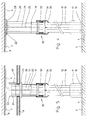
- Fig. 3 shows a ceiling height as a third embodiment Energy column, clamped between floor 7 and concrete ceiling 8.
- the cylinder tube 10 stands on a foot 14 ′′.
- a bracing unit 30 attached, which is explained in more detail with reference to FIG. 12 shall be.
- Above the tensioning unit 30 is a Telescopic tube 20 is provided, which from one in the Bracing unit 30 provided spring 32 against the Concrete ceiling 8 is pressed.
- a ceiling rose 23 concealed the ceiling-side end of the telescopic tube 20.
- FIG. 4 shows a first in a schematic representation Embodiment of a ceiling-high energy column.
- the Cylinder tube 10 stands on a base plate 16 (see Fig. 7), which in turn lies on the floor 7.
- a two-part kick sleeve 17 covers the lower end of the cylinder tube 10 and the base plate 16.
- a removable cover 12 are accessible.
- the clamping unit 30 presses in Telescopic tube 20 with a removable cover 21 against one Head plate 22 (see Fig. 11), which in turn on the Concrete ceiling 8 supports.
- Fig. 5 shows a second embodiment of a ceiling-high energy column, which is connected to a false ceiling 9 is attached.
- a clamping part 40 is provided, which will be explained in more detail with reference to FIG. 13.
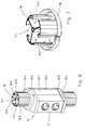
- Fig. 6 shows a perspective view Section of an energy column in the area of a Electrical installation device 2, here a double socket.
- the three cable ducts 11.1 can be seen in the cylinder tube 10, 11.2, 11.3, each by a cover 12.1, 12.2, 12.3 are closed.
- the covers 12.1, 12.2, 12.3 are made preferably made of a rubber-elastic material, so that an electrical line 4 at any point a cable duct 11 can be led out without the Cover 12.1, 12.2, 12.3 must be cut out.
- the receptacle 13 for the electrical installation device 2 exists from a front part 13.1 and a back part 13.2, which with With the help of clamping screws 13.3 are connected to each other, so that the receptacle 13 under tension on the cylinder tube 10 is held.
- the lower and upper end of the receptacle 13 formed as a channel 13.4 so that electrical lines each of the three cable channels 11.1, 11.2, 11.3 invisible led out and to the electrical installation device 2 can be connected. Thanks to the channel construction 13.4 there is the possibility of receiving 13 over the To twist cylinder tube 10, even if that Electrical installation device 2 is already connected.
- Fig. 7 shows a perspective view sections of the bottom end of an energy column.
- the cylinder tube 10 sits on the Base plate 16, which in turn on the floor (not shown) rests.
- FIG. 8 shows a cross section through the telescopic tube 20 with lid 21. Both are made of aluminum.
- Fig. 9 shows a perspective view of the lower end of the telescopic tube 20 with the telescopic tube cover removed.
- the telescopic tube 20 sits on a slide ring 31, the part the tensioning unit 30.
- the telescopic tube 20 can on the Slide ring 31 can be rotated through 360 ° so that through the open Front of the telescopic tube of each of the three cable channels 11.1, 11.2, 11.3 is accessible.
- the sliding ring 31 On its underside, the sliding ring 31 has one tapered collar 31.1, which is a sliding connection for Tension spring 32 of the clamping unit 30 produces.
- Fig. 10 shows the upper end of the telescopic tube 20.
- a telescopic slide ring 24 is provided.
- This has a hinged to be opened by means of film hinge 24.2 Section 24.1. This enables the insertion of electrical lines without threading.
- Fig. 11 shows the head plate 22 which between Telescopic slide ring 24 and concrete ceiling 8 is positioned.
- the Head plate is equipped with fastening eyes 27.
- she has recesses 26 for the electrical lines 4.
- the telescopic slide ring 24 (FIG. 10) with its opening one Section 24.1 also rotated relative to the head plate 22 can be, the electrical lines 4 without Insert the threading process into each recess 26.
- the head plate 22 also carries one on its underside Bracket 28, can be clipped onto the partition walls 25.
- the shape and length of the partition 25 are on the cylinder tube 10 and the cable ducts 11.1, 11.2, 11.3 provided therein customized.
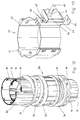
- Fig. 12 shows the perspective view Bracing unit 30.
- the two-part clamping ring 34 pinched.
- the tension spring 32 sits on top of this, which in turn presses against the slide ring 31 from below.
- the Threaded sleeve 33 can be turned by hand. Sits the Bracing unit 30 approximately at head height, the Mount the ceiling-high energy column comfortably from the floor and tense. After assembly, the tensioning unit 30 from the two-part lamination sleeve 35 (FIGS. 4 and 5) covered.
- Fig. 13 shows a perspective view of the clamping part 40 for fastening the energy column to the false ceiling 9 (Fig. 5).
- the clamping part 40 is in two parts and consists of a clamping part front part 41 and a clamping part rear part 42. At this bottom there is the bracket 49 which the Connects to the false ceiling 9. With the help of Hexagon screw 45, lock washer 48, hexagon nuts 47 and wing nut 46 in connection with the two tabs 43, 44, the clamping part 40 is attached to the false ceiling 9.
Landscapes
- Engineering & Computer Science (AREA)
- Architecture (AREA)
- Civil Engineering (AREA)
- Structural Engineering (AREA)
- Power Engineering (AREA)
- Organic Low-Molecular-Weight Compounds And Preparation Thereof (AREA)
- Details Of Indoor Wiring (AREA)
- Secondary Cells (AREA)
- Catalysts (AREA)
- Rod-Shaped Construction Members (AREA)
- Current-Collector Devices For Electrically Propelled Vehicles (AREA)
- Transition And Organic Metals Composition Catalysts For Addition Polymerization (AREA)
- Forklifts And Lifting Vehicles (AREA)
- Installation Of Indoor Wiring (AREA)
Abstract
Description
- Fig. 1
- eine tischhohe Energiesäule in perspektivischer Darstellung,
- Fig. 2
- eine wandseitig montierte Energiesäule in perspektivischer Darstellung,
- Fig. 3
- eine deckenhohe Energiesäule in perspektivischer Darstellung,
- Fig. 4
- eine Ausführungsform einer deckenhohen Energiesäule in schematischer Darstellung,
- Fig. 5
- eine Ausführungsform einer zwischendeckenhohen Energiesäule in schematischer Darstellung,
- Fig. 6
- eine Aufnahme für Elektroinstallationsgeräte, montiert an der Energiesäule, in perspektivischer Darstellung,
- Fig. 7
- den Bodenbereich einer Energiesäule in perspektivischer Darstellung,
- Fig. 8
- einen Querschnitt durch ein Teleskoprohr,
- Fig. 9
- das untere Ende des Teleskoprohrs in perspektivischer Darstellung,
- Fig. 10
- das obere Ende des Teleskoprohrs in perspektivischer Darstellung,
- Fig. 11
- eine Kopfplatte mit angeclipster Trennwand in perspektivischer Darstellung,
- Fig. 12
- einen Ausschnitt aus einer Energiesäule im Bereich der Verspanneinheit in perspektivischer Darstellung und
- Fig. 13
- ein Klemmteil zur deckenseitigen Befestigung der Energiesäule an einer Zwischendecke in perspektivischer Darstellung.
Claims (20)
- Energiesäule zum Aufstellen in Räumen zwecks Bereitstellung von Elektroinstallationsgeräten (1, 2) - Steckdosen, Sicherungsautomaten, Schalter usw. - an beliebigen Plätzen und in beliebigen Höhen, umfassendgekennzeichnet durch die Merkmale:ein Zylinderrohr (10),-- darin wenigstens einen Kabelkanal (11) für elektrische Leitungen (4),-- daran wenigstens einen Deckel (12) zum lösbaren Verschließen des Kabelkanals (11)-- und daran wenigstens eine Aufnahme (13) für das Elektroinstallationsgerät (1, 2),einen Fuß (14, 14', 14''),-- verbunden mit dem Zylinderrohr (10)-- und gegebenenfalls mit einer Einrichtung zum Einführen der elektrischen Leitungen in den Kabelkanal (11) ausgerüstet,das Zylinderrohr (10) besitzt einen kreisförmigen bzw. der Kreisform angenäherten polygonalen Querschnitt,der Fuß (14, 14', 14'') ist unter dem Zylinderrohr (10) befestigt,die Aufnahme (13) für das Installationsgerät (1, 2) ist auf das Zylinderrohr (10) aufgeklemmt.
- Energiesäule nach Anspruch 1, gekennzeichnet durch das Merkmal:im Zylinderrohr (10) sind drei Kabelkanäle (11.1, 11.2, 11.3) vorgesehen.
- Energiesäule nach Anspruch 1 oder 2, gekennzeichnet durch das Merkmal:eine Längskante des Deckels (12) ist als elastische Lippe (12.4) ausgebildet.
- Energiesäule nach Anspruch 1, 2 oder 3, gekennzeichnet durch das Merkmal:der Deckel (12) zum lösbaren Verschließen des Kabelkanals (11.1, 11.2, 11.3) besteht aus einem gummielastischen Material.
- Energiesäule nach einem der Ansprüche 1 bis 4, gekennzeichnet durch die Merkmale:das Zylinderrohr (10) ist halbhoch,auf sein oberes Ende ist eine Endplatte (15) aufgesteckt.
- Energiesäule nach Anspruch 5, gekennzeichnet durch das Merkmal:die Endplatte (15) hat die Form einer Tischplatte.
- Energiesäule nach einem der Ansprüche 1 bis 4, gekennzeichnet durch die Merkmale:es ist ein Teleskoprohr (20) vorgesehen,auf das Teleskoprohr (20) ist eine Kopfplatte (22) aufgesetzt,auf das Zylinderrohr (10) ist eine Verspanneinheit (30) aufgeklemmt, bestehend aus-- einem Spannring (34) mit Spanngewinde (37),-- einer Gewindehülse (33) auf dem Spanngewinde (37),-- einer Spannfeder (32) auf der Gewindehülse (33)-- und einem Gleitring (31) auf der Spannfeder (32),das Teleskoprohr (20) sitzt auf dem Gleitring (31) auf,eine Kaschierhülse (35) deckt die Verspanneinheit (30) ab.
- Energiesäule nach Anspruch 7, gekennzeichnet durch die Merkmale:das Teleskoprohr (20) ist- die Öffnung ist mit einem Teleskoprohrdeckel (21) verschließbar.-- einseitig offen-- und um 360° drehbar,
- Energiesäule nach Anspruch 7 oder 8, gekennzeichnet durch das Merkmal:die Verspanneinheit (30) ist in Kopfhöhe montiert.
- Energiesäule nach Anspruch 7, gekennzeichnet durch das Merkmal:der Spannring (34) besteht-- aus einem Klemmring-- und einem Gewindeteil.
- Energiesäule nach einem der Ansprüche 7 bis 10, gekennzeichnet durch das Merkmal:das Zylinderrohr (10) steht auf einer Bodenplatte (16),eine Trittschutzhülse (17) kaschiert das bodenseitige Ende des Zylinderrohrs (10).
- Energiesäule nach einem der Ansprüche 7 bis 11, gekennzeichnet durch das Merkmal:zwischen Teleskoprohr (20) und Kopfplatte (22) sitzt ein Teleskopgleitring (24).
- Energiesäule nach Anspruch 12, gekennzeichnet durch das Merkmal:der Teleskopgleitring (24) besitzt ein zu öffnendes Teilstück (24.1).
- Energiesäule nach einem der Ansprüche 7 bis 13, gekennzeichnet durch das Merkmal:es ist ein Klemmteil (40) vorgesehen,-- zu verbinden mit dem Teleskoprohr (20, 21),das Klemmteil (40)-- ist zweiteilig-- und besitzt einen Haltewinkel (49) zur Befestigung des Klemmteils (40) auf einer Zwischendecke (9).
- Energiesäule nach einem der Ansprüche 7 bis 14, gekennzeichnet durch das Merkmal:die Kopfplatte (22) besitzt Aussparungen (26) zum Einführen von elektrischen Leitungen.
- Energiesäule nach einem der Ansprüche 7 bis 15, gekennzeichnet durch das Merkmal:die Kopfplatte (22) besitzt eine Halterung (28) zum Befestigen von Trennwänden (25).
- Energiesäule nach einem der Ansprüche 7 bis 16, gekennzeichnet durch das Merkmal:Spannring (34), Trittschutzhülse (17), Deckenrosette (23) und/oder Kaschierhülse (35) sind zweiteilig.
- Energiesäule nach einem der Ansprüche 1 bis 17, gekennzeichnet durch das Merkmal:die Aufnahme (13) für die Elektroinstallationsgeräte (1, 2) besitzt wenigstens einen Kanal (13.4) für die unsichtbare Führung einer elektrischen Leitung aus einem Kabelkanal (11) zum Elektroinstallationsgerät (1, 2, 3).
- Energiesäule nach einem der Ansprüche 1 bis 18, gekennzeichnet durch das Merkmal:die Aufnahme (13) für die Elektroinstallationsgeräte (1, 2) ist zweiteilig.
- Energiesäule nach einem der Ansprüche 1 bis 19, gekennzeichnet durch das Merkmal:Gleitring (31), Teleskopgleitring (24), Gewindeteil (37), Gewindehülse (33), Kopfplatte (22) und Trennwand (25) bestehen aus Kunststoff,Zylinderrohr (10), Teleskoprohr (20), Teleskoprohrdeckel (21) und Klemmring (34) bestehen aus Aluminium.
Applications Claiming Priority (2)
| Application Number | Priority Date | Filing Date | Title |
|---|---|---|---|
| DE29615033U | 1996-08-29 | ||
| DE29615033U DE29615033U1 (de) | 1996-08-29 | 1996-08-29 | Energiesäule |
Publications (3)
| Publication Number | Publication Date |
|---|---|
| EP0828326A2 true EP0828326A2 (de) | 1998-03-11 |
| EP0828326A3 EP0828326A3 (de) | 1999-03-10 |
| EP0828326B1 EP0828326B1 (de) | 2002-01-16 |
Family
ID=8028513
Family Applications (1)
| Application Number | Title | Priority Date | Filing Date |
|---|---|---|---|
| EP97114684A Expired - Lifetime EP0828326B1 (de) | 1996-08-29 | 1997-08-25 | Energiesäule |
Country Status (6)
| Country | Link |
|---|---|
| EP (1) | EP0828326B1 (de) |
| AT (1) | ATE212153T1 (de) |
| DE (2) | DE29615033U1 (de) |
| DK (1) | DK0828326T3 (de) |
| ES (1) | ES2170308T3 (de) |
| NO (1) | NO313168B1 (de) |
Cited By (9)
| Publication number | Priority date | Publication date | Assignee | Title |
|---|---|---|---|---|
| FR2817719A1 (fr) * | 2000-12-08 | 2002-06-14 | Electric Production | Colonne bureautique |
| EP1335462A3 (de) * | 2002-02-08 | 2003-11-12 | Aparellaje Electrico S.L. | Binnensaüle für Niederspannungstromverbindung |
| DE10120528B4 (de) * | 2000-04-27 | 2006-02-02 | Thorsman & Co. Ab | Bestückpfeiler und Deckbefestigung für einen solchen |
| EP1816717A1 (de) | 2006-02-04 | 2007-08-08 | Tehalit GmbH | Versorgungssäule |
| DE202008003510U1 (de) | 2008-03-12 | 2008-06-05 | Hidde, Axel R., Dr. Ing. | Energiesäule für die Außenanwendung |
| DE202009008037U1 (de) | 2009-06-09 | 2009-09-24 | Tehalit Gmbh | Spannvorrichtung für Versorgungssäulen und Raumsäulen mit Anschlüssen und Geräten für elektrische Energie, Telekommunikation und/oder Daten |
| DE202017006194U1 (de) | 2017-11-27 | 2018-01-11 | Jens Holtkamp | Steckdosenspieß |
| FR3060883A1 (fr) * | 2016-12-20 | 2018-06-22 | Legrand France | Colonne pour le support d’au moins un appareillage electrique et/ou le cheminement de cables |
| DE202021102987U1 (de) | 2021-05-31 | 2021-11-08 | Patrick Siehr | Spannvorrichtung |
Families Citing this family (10)
| Publication number | Priority date | Publication date | Assignee | Title |
|---|---|---|---|---|
| DE19949886C1 (de) * | 1999-10-15 | 2001-08-09 | Loh Kg Rittal Werk | Stütze für ein elektrische oder elektronische Einheiten aufnehmendes Gehäuse |
| DE10064126C1 (de) * | 2000-12-21 | 2002-07-04 | Kathrein Werke Kg | Kabeldurchführung |
| DE202004013935U1 (de) | 2004-09-08 | 2006-01-12 | Tehalit Gmbh & Co. Kg | Energiesäule |
| DE102005039088B4 (de) * | 2005-07-21 | 2015-07-02 | GfP (Gesellschaft für Produktivitätsplanung und Produktentwicklung) mbH | Installationseinrichtung |
| DE102008014851B3 (de) * | 2008-03-18 | 2009-05-20 | Heiner Rottbeck | Stromverteilersystem für Baustellen |
| GB2464546B (en) * | 2008-10-21 | 2013-04-03 | Icon Office Design Ltd | A support stand |
| DE202008016943U1 (de) | 2008-12-20 | 2010-05-27 | Tehalit Gmbh | Energiesäule mit mechanischer und elektrischer Kontaktierung |
| DE102010000207A1 (de) | 2010-01-26 | 2011-07-28 | Rittal GmbH & Co. KG, 35745 | Adapter zur Befestigung eines Tragprofils |
| DE102011013166A1 (de) * | 2011-02-24 | 2012-08-30 | Elektroinstallation Lutz Skladny GmbH | Vorrichtung zur variablen Strom- und Datenversorgung von Aktionsplätzen |
| GB2608384B (en) * | 2021-06-29 | 2024-03-13 | Yunex Ltd | Floor-to-ceiling mounting post for electrical equipment |
Citations (4)
| Publication number | Priority date | Publication date | Assignee | Title |
|---|---|---|---|---|
| FR2290064A1 (fr) * | 1974-10-29 | 1976-05-28 | Bauer Ag | Installation pour l'amenee d'informations et d'energie dans un local, en particulier un bureau de grande surface |
| GB1453952A (en) * | 1973-03-27 | 1976-10-27 | Space Tasks Ltd | Distribution apparatus for electrical services photographic supp |
| EP0514862A1 (de) * | 1991-05-22 | 1992-11-25 | ABB Elettrocondutture S.p.A. | Elektrische Verteilsäule, insbesondere für schwimmenden Fussboden und dergleichen |
| FR2727577A1 (fr) * | 1994-11-29 | 1996-05-31 | Electric Production | Colonne technique adaptee a supporter des appareils, de commande et/ou de distribution, connectes a des cables, et a recevoir lesdits cables |
-
1996
- 1996-08-29 DE DE29615033U patent/DE29615033U1/de not_active Expired - Lifetime
-
1997
- 1997-08-22 NO NO19973867A patent/NO313168B1/no unknown
- 1997-08-25 EP EP97114684A patent/EP0828326B1/de not_active Expired - Lifetime
- 1997-08-25 DK DK97114684T patent/DK0828326T3/da active
- 1997-08-25 DE DE59705992T patent/DE59705992D1/de not_active Expired - Fee Related
- 1997-08-25 AT AT97114684T patent/ATE212153T1/de not_active IP Right Cessation
- 1997-08-25 ES ES97114684T patent/ES2170308T3/es not_active Expired - Lifetime
Patent Citations (4)
| Publication number | Priority date | Publication date | Assignee | Title |
|---|---|---|---|---|
| GB1453952A (en) * | 1973-03-27 | 1976-10-27 | Space Tasks Ltd | Distribution apparatus for electrical services photographic supp |
| FR2290064A1 (fr) * | 1974-10-29 | 1976-05-28 | Bauer Ag | Installation pour l'amenee d'informations et d'energie dans un local, en particulier un bureau de grande surface |
| EP0514862A1 (de) * | 1991-05-22 | 1992-11-25 | ABB Elettrocondutture S.p.A. | Elektrische Verteilsäule, insbesondere für schwimmenden Fussboden und dergleichen |
| FR2727577A1 (fr) * | 1994-11-29 | 1996-05-31 | Electric Production | Colonne technique adaptee a supporter des appareils, de commande et/ou de distribution, connectes a des cables, et a recevoir lesdits cables |
Cited By (12)
| Publication number | Priority date | Publication date | Assignee | Title |
|---|---|---|---|---|
| DE10120528B4 (de) * | 2000-04-27 | 2006-02-02 | Thorsman & Co. Ab | Bestückpfeiler und Deckbefestigung für einen solchen |
| FR2817719A1 (fr) * | 2000-12-08 | 2002-06-14 | Electric Production | Colonne bureautique |
| EP1335462A3 (de) * | 2002-02-08 | 2003-11-12 | Aparellaje Electrico S.L. | Binnensaüle für Niederspannungstromverbindung |
| EP1816717A1 (de) | 2006-02-04 | 2007-08-08 | Tehalit GmbH | Versorgungssäule |
| DE202008003510U1 (de) | 2008-03-12 | 2008-06-05 | Hidde, Axel R., Dr. Ing. | Energiesäule für die Außenanwendung |
| DE102008015771A1 (de) | 2008-03-12 | 2010-04-22 | Hidde, Axel R., Dr. Ing. | Energiesäule für die Aussenanwendung |
| DE202009008037U1 (de) | 2009-06-09 | 2009-09-24 | Tehalit Gmbh | Spannvorrichtung für Versorgungssäulen und Raumsäulen mit Anschlüssen und Geräten für elektrische Energie, Telekommunikation und/oder Daten |
| EP2262070A2 (de) | 2009-06-09 | 2010-12-15 | Tehalit GmbH | Spannvorrichtung für Versorgungssäulen und Raumsäulen mit Anschlüssen und Geräten für elektrische Energie, Telekommunikation und/oder Daten |
| FR3060883A1 (fr) * | 2016-12-20 | 2018-06-22 | Legrand France | Colonne pour le support d’au moins un appareillage electrique et/ou le cheminement de cables |
| EP3340407A1 (de) * | 2016-12-20 | 2018-06-27 | Legrand France | Säule als halterung für mindestens ein elektrogerät und/oder den kabelkanal |
| DE202017006194U1 (de) | 2017-11-27 | 2018-01-11 | Jens Holtkamp | Steckdosenspieß |
| DE202021102987U1 (de) | 2021-05-31 | 2021-11-08 | Patrick Siehr | Spannvorrichtung |
Also Published As
| Publication number | Publication date |
|---|---|
| DE29615033U1 (de) | 1998-01-02 |
| NO313168B1 (no) | 2002-08-19 |
| NO973867L (no) | 1998-03-02 |
| DE59705992D1 (de) | 2002-02-21 |
| ES2170308T3 (es) | 2002-08-01 |
| EP0828326A3 (de) | 1999-03-10 |
| DK0828326T3 (da) | 2002-05-06 |
| ATE212153T1 (de) | 2002-02-15 |
| NO973867D0 (no) | 1997-08-22 |
| EP0828326B1 (de) | 2002-01-16 |
Similar Documents
| Publication | Publication Date | Title |
|---|---|---|
| EP0828326B1 (de) | Energiesäule | |
| DE2145453A1 (de) | Tisch mit einer Anordnung zum Aufnehmen von Geräteanschlußkabeln | |
| DE2620429C2 (de) | Unterdecke | |
| DE3438650A1 (de) | Tisch, insbesondere reihfaehiger konferenztisch | |
| EP2763256B1 (de) | Kabelkanal mit Durchgangsabschluss, Bausatz für einen Durchgangsabschluss und Verfahren zum Montieren eines Durchgangsabschlusses für einen Kabelkanal | |
| DE19623708C1 (de) | Lüftungseinrichtung | |
| DE4331125A1 (de) | Winkelstück | |
| DE102007002902B4 (de) | Anordnung zur universellen Kabeldurchführung | |
| DE202006006183U1 (de) | Möbel | |
| EP0582945A2 (de) | Multifunktionales Wandelment für Büro- und sonstige Arbeitsplatzeinrichtungen | |
| CH435396A (de) | Leitungskanal zur Verlegung und Montage von elektrischen Leitungen, Kabeln und Anschlussapparaten an Wänden und Brüstungen, insbesondere Fensterbrüstungen | |
| EP0551610A1 (de) | Einbaustrahler | |
| DE3507896C2 (de) | ||
| EP1013196B1 (de) | Geräteständer | |
| EP2250930A1 (de) | Versorgungssystem zum Bereitstellen einer Medienversorgung | |
| DE102008001461A1 (de) | Befestigungssockel für Energiesäulen oder Stehleuchten | |
| DE19609989C2 (de) | Kombination von Mobiliar aller Art mit einem ortsveränderlichen Elektroanlagensystem für dauernde Nutzung in bezugsfertigen Räumen und Hallen | |
| DE4403593A1 (de) | Drehgelenk aus zwei über Lagerwände drehbar miteinander verbundenen Gelenkteilen | |
| DE102004018472A1 (de) | Installationsbauelement zur Unterbringung von Versorgungsleitungen | |
| DE19835837B4 (de) | Anordnung zur Halterung und Montage von elektrischen Installationsgeräten | |
| EP1458057B1 (de) | Berührsichere Dose | |
| DE1615645C3 (de) | Auslaß für einen im Fußboden angeordneten Schacht für elektrische Installationen | |
| DE7613289U1 (de) | Aufsatzkasten zur Aufnahme elektrischer Installationseinheiten | |
| DE2442945C3 (de) | Installationseinrichtung für eine Versorgung mit Schwach- und Starkstrom aus einer Zwischendecke | |
| EP0680125B1 (de) | Einbaudose |
Legal Events
| Date | Code | Title | Description |
|---|---|---|---|
| PUAI | Public reference made under article 153(3) epc to a published international application that has entered the european phase |
Free format text: ORIGINAL CODE: 0009012 |
|
| AK | Designated contracting states |
Kind code of ref document: A2 Designated state(s): AT BE CH DE DK ES FI FR GB IT LI NL SE |
|
| PUAL | Search report despatched |
Free format text: ORIGINAL CODE: 0009013 |
|
| AK | Designated contracting states |
Kind code of ref document: A3 Designated state(s): AT BE CH DE DK ES FI FR GB GR IE IT LI LU MC NL PT SE |
|
| 17P | Request for examination filed |
Effective date: 19990412 |
|
| AKX | Designation fees paid |
Free format text: AT BE CH DE DK ES FI FR GB IT LI NL SE |
|
| 17Q | First examination report despatched |
Effective date: 20001127 |
|
| GRAG | Despatch of communication of intention to grant |
Free format text: ORIGINAL CODE: EPIDOS AGRA |
|
| RAP1 | Party data changed (applicant data changed or rights of an application transferred) |
Owner name: TEHALIT GMBH & CO. KG |
|
| GRAG | Despatch of communication of intention to grant |
Free format text: ORIGINAL CODE: EPIDOS AGRA |
|
| GRAH | Despatch of communication of intention to grant a patent |
Free format text: ORIGINAL CODE: EPIDOS IGRA |
|
| GRAH | Despatch of communication of intention to grant a patent |
Free format text: ORIGINAL CODE: EPIDOS IGRA |
|
| GRAA | (expected) grant |
Free format text: ORIGINAL CODE: 0009210 |
|
| REG | Reference to a national code |
Ref country code: GB Ref legal event code: IF02 |
|
| AK | Designated contracting states |
Kind code of ref document: B1 Designated state(s): AT BE CH DE DK ES FI FR GB IT LI NL SE |
|
| REF | Corresponds to: |
Ref document number: 212153 Country of ref document: AT Date of ref document: 20020215 Kind code of ref document: T |
|
| REG | Reference to a national code |
Ref country code: CH Ref legal event code: EP |
|
| REF | Corresponds to: |
Ref document number: 59705992 Country of ref document: DE Date of ref document: 20020221 |
|
| REG | Reference to a national code |
Ref country code: CH Ref legal event code: NV Representative=s name: PATENTANWAELTE SCHAAD, BALASS, MENZL & PARTNER AG |
|
| REG | Reference to a national code |
Ref country code: DK Ref legal event code: T3 |
|
| GBT | Gb: translation of ep patent filed (gb section 77(6)(a)/1977) |
Effective date: 20020416 |
|
| ET | Fr: translation filed | ||
| REG | Reference to a national code |
Ref country code: ES Ref legal event code: FG2A Ref document number: 2170308 Country of ref document: ES Kind code of ref document: T3 |
|
| PLBE | No opposition filed within time limit |
Free format text: ORIGINAL CODE: 0009261 |
|
| STAA | Information on the status of an ep patent application or granted ep patent |
Free format text: STATUS: NO OPPOSITION FILED WITHIN TIME LIMIT |
|
| 26N | No opposition filed | ||
| PGFP | Annual fee paid to national office [announced via postgrant information from national office to epo] |
Ref country code: DE Payment date: 20040729 Year of fee payment: 8 |
|
| PGFP | Annual fee paid to national office [announced via postgrant information from national office to epo] |
Ref country code: GB Payment date: 20040810 Year of fee payment: 8 |
|
| PGFP | Annual fee paid to national office [announced via postgrant information from national office to epo] |
Ref country code: NL Payment date: 20040819 Year of fee payment: 8 Ref country code: FR Payment date: 20040819 Year of fee payment: 8 |
|
| PGFP | Annual fee paid to national office [announced via postgrant information from national office to epo] |
Ref country code: FI Payment date: 20040823 Year of fee payment: 8 Ref country code: BE Payment date: 20040823 Year of fee payment: 8 |
|
| PGFP | Annual fee paid to national office [announced via postgrant information from national office to epo] |
Ref country code: CH Payment date: 20040824 Year of fee payment: 8 Ref country code: AT Payment date: 20040824 Year of fee payment: 8 |
|
| PGFP | Annual fee paid to national office [announced via postgrant information from national office to epo] |
Ref country code: SE Payment date: 20040825 Year of fee payment: 8 Ref country code: DK Payment date: 20040825 Year of fee payment: 8 |
|
| PGFP | Annual fee paid to national office [announced via postgrant information from national office to epo] |
Ref country code: ES Payment date: 20040826 Year of fee payment: 8 |
|
| PG25 | Lapsed in a contracting state [announced via postgrant information from national office to epo] |
Ref country code: IT Free format text: LAPSE BECAUSE OF NON-PAYMENT OF DUE FEES;WARNING: LAPSES OF ITALIAN PATENTS WITH EFFECTIVE DATE BEFORE 2007 MAY HAVE OCCURRED AT ANY TIME BEFORE 2007. THE CORRECT EFFECTIVE DATE MAY BE DIFFERENT FROM THE ONE RECORDED. Effective date: 20050825 Ref country code: GB Free format text: LAPSE BECAUSE OF NON-PAYMENT OF DUE FEES Effective date: 20050825 Ref country code: FI Free format text: LAPSE BECAUSE OF NON-PAYMENT OF DUE FEES Effective date: 20050825 Ref country code: AT Free format text: LAPSE BECAUSE OF NON-PAYMENT OF DUE FEES Effective date: 20050825 |
|
| PG25 | Lapsed in a contracting state [announced via postgrant information from national office to epo] |
Ref country code: SE Free format text: LAPSE BECAUSE OF NON-PAYMENT OF DUE FEES Effective date: 20050826 Ref country code: ES Free format text: LAPSE BECAUSE OF NON-PAYMENT OF DUE FEES Effective date: 20050826 |
|
| PG25 | Lapsed in a contracting state [announced via postgrant information from national office to epo] |
Ref country code: LI Free format text: LAPSE BECAUSE OF NON-PAYMENT OF DUE FEES Effective date: 20050831 Ref country code: DK Free format text: LAPSE BECAUSE OF NON-PAYMENT OF DUE FEES Effective date: 20050831 Ref country code: CH Free format text: LAPSE BECAUSE OF NON-PAYMENT OF DUE FEES Effective date: 20050831 Ref country code: BE Free format text: LAPSE BECAUSE OF NON-PAYMENT OF DUE FEES Effective date: 20050831 |
|
| PG25 | Lapsed in a contracting state [announced via postgrant information from national office to epo] |
Ref country code: NL Free format text: LAPSE BECAUSE OF NON-PAYMENT OF DUE FEES Effective date: 20060301 Ref country code: DE Free format text: LAPSE BECAUSE OF NON-PAYMENT OF DUE FEES Effective date: 20060301 |
|
| REG | Reference to a national code |
Ref country code: CH Ref legal event code: PL |
|
| REG | Reference to a national code |
Ref country code: DK Ref legal event code: EBP |
|
| EUG | Se: european patent has lapsed | ||
| GBPC | Gb: european patent ceased through non-payment of renewal fee |
Effective date: 20050825 |
|
| PG25 | Lapsed in a contracting state [announced via postgrant information from national office to epo] |
Ref country code: FR Free format text: LAPSE BECAUSE OF NON-PAYMENT OF DUE FEES Effective date: 20060428 |
|
| NLV4 | Nl: lapsed or anulled due to non-payment of the annual fee |
Effective date: 20060301 |
|
| REG | Reference to a national code |
Ref country code: FR Ref legal event code: ST Effective date: 20060428 |
|
| REG | Reference to a national code |
Ref country code: ES Ref legal event code: FD2A Effective date: 20050826 |
|
| BERE | Be: lapsed |
Owner name: *TEHALIT G.M.B.H. & CO. K.G. Effective date: 20050831 |