EP1816717A1 - Versorgungssäule - Google Patents
Versorgungssäule Download PDFInfo
- Publication number
- EP1816717A1 EP1816717A1 EP07001246A EP07001246A EP1816717A1 EP 1816717 A1 EP1816717 A1 EP 1816717A1 EP 07001246 A EP07001246 A EP 07001246A EP 07001246 A EP07001246 A EP 07001246A EP 1816717 A1 EP1816717 A1 EP 1816717A1
- Authority
- EP
- European Patent Office
- Prior art keywords
- supply column
- carriage
- column according
- tension spring
- feature
- Prior art date
- Legal status (The legal status is an assumption and is not a legal conclusion. Google has not performed a legal analysis and makes no representation as to the accuracy of the status listed.)
- Granted
Links
- 238000010276 construction Methods 0.000 description 2
- 238000009434 installation Methods 0.000 description 2
- 238000000034 method Methods 0.000 description 2
- 238000005096 rolling process Methods 0.000 description 1
Images


Classifications
-
- H—ELECTRICITY
- H02—GENERATION; CONVERSION OR DISTRIBUTION OF ELECTRIC POWER
- H02G—INSTALLATION OF ELECTRIC CABLES OR LINES, OR OF COMBINED OPTICAL AND ELECTRIC CABLES OR LINES
- H02G3/00—Installations of electric cables or lines or protective tubing therefor in or on buildings, equivalent structures or vehicles
- H02G3/02—Details
- H02G3/04—Protective tubing or conduits, e.g. cable ladders or cable troughs
- H02G3/0493—Service poles
Definitions
- the invention relates to utility columns for the supply of office and other rooms with terminals and devices for electrical energy, telecommunications or data according to the preamble of claim 1.
- some supply columns have a carriage, which is housed in the body of the supply column and is permanently fixed there after moving to the required position.
- ordinary threaded screws are used.
- the installation of the known supply columns takes place in several steps. First, the column is set up. Then the sled is driven into the expected correct height and fixed. This usually requires two people, one holding the column and the other fixing the sled. Then the tension spring is tensioned. Since the tensioning device is often located in the ceiling area, the installer has to climb onto the ladder. If it now turns out that the clamping force of the tension spring is too big or too small, the process must be repeated. Depending on the particularities of the installation site, this process can occupy two installers over a longer period of time. That is unsatisfactory.
- the present invention has for its object to provide a supply column of the type mentioned, which can be clamped by a single person in the shortest possible time between floor and ceiling.
- the fixing of the carriage takes place in the body of the supply column and the subsequent tensioning of the tension spring with a single handle. It is ensured by skillful dimensioning of the construction elements that initially the carriage fixed and then the tension spring is tensioned.
- the installer first moves the carriage upwards with the clamping and pressing device released until the head lays against the ceiling. Then he only has to swing the swivel lever into the closed position and the space column sits perfectly with the right tension between floor and ceiling.
- the lifting device comprises a roller which is mounted on the pivot lever. On this role rests the lower end of the push rod. Due to the low friction of such a role, both the wear and the operating force are significantly reduced.
- the clamping device comprises an eccentric.
- this eccentric is positioned in the region of the pivot axis of the pivot lever. This eccentric causes the fixation of the carriage in the column body at the desired height.
- the carriage comprises a resilient tongue, which is pressed by the clamping device, in particular by the eccentric, against the body.
- a resilient tongue increases the contact surface between the carriage and column body and simultaneously reduces wear.
- the carriage has U-shaped skids, which run on a T-rail in the body.
- a gap is formed between the carcass and the carriage.
- the clamping device comprises a wedge, which dips into the gap and thus ensures the frictional engagement.
- a spring is provided which presses the wedge into the gap.
- a device for releasing the wedge is provided on the pivot lever. This ensures that the wedge can not accidentally come loose by itself.
- the tension spring is a gas spring.
- the tension spring may be formed as an air-filled rubber bellows.
- the tension spring is a cup spring package.
- the tension spring is a spiral spring.
- the selection of the respective tension spring depends on the one hand on the spatial conditions, on the other hand of the forces required for the bracing.
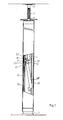
- Fig. 1 shows purely schematically and partially broken a supply column for the supply of office and other rooms with terminals and devices for electrical energy, telecommunications and / or data.
- a carriage 20 which has U-shaped skids 22 which run on a T-rail 12 in the body 10.
- Fig. 2 shows the clamping, lifting and clamping device from the supply column of Fig. 1 in isometric view. It can be seen the carriage 20 with U-shaped skids 22 and a resilient tongue 21. It also recognizes a pivot axis 33 to which a pivot lever 30 is articulated. The push rod 4 is guided vertically movable in a number of brackets 24.
- the pivot lever 30 is pivotally mounted about an axis 33.
- the pivot lever 30 is designed as an eccentric disk 31.
- a resilient tongue 21 is provided on the carriage 20. If the pivot lever 30 is pivoted upwards in the direction of the arrow, the eccentric disk 31 bears against the tongue 21 and presses it against the T rail 12. In this way, the carriage 20 is pivoted at the desired height on the column body by simply pivoting the pivot lever 30 in the direction of the arrow 10 fixed.
- Fig. 3 shows a section of the column body with an alternative clamping, lifting and clamping device.
- a gap 11 is formed, in which from below a wedge 34 so immersed that the carriage 20 is fixed to the body 10.
- a spring 23 presses the wedge 34 into the gap and thus prevents accidental release.
- a nose 35 is provided on the pivot lever 30, which pushes the wedge 34 downwardly out of the gap 11 as soon as the pivot lever 30 is pivoted in the direction of the arrow upwards.
- the pivoting lever 30 is pivoted downwards in the direction of the arrow, whereupon the spring 23 presses the wedge 34 into the gap 11.
- the roller 32 is mounted off-center. In the clamping position indicated by dashed lines, the roller 32 'is again beyond the summit position and to the right of the pivot axis 33. In this way it is ensured that the pivot lever 30' can not accidentally come loose by itself.
Landscapes
- Engineering & Computer Science (AREA)
- Architecture (AREA)
- Civil Engineering (AREA)
- Structural Engineering (AREA)
- Saccharide Compounds (AREA)
- Stereophonic System (AREA)
- Electrophonic Musical Instruments (AREA)
- Telephone Set Structure (AREA)
- Earth Drilling (AREA)
- Mechanisms For Operating Contacts (AREA)
- Mutual Connection Of Rods And Tubes (AREA)
- Holders For Apparel And Elements Relating To Apparel (AREA)
- Clamps And Clips (AREA)
- Ladders (AREA)
- Conductive Materials (AREA)
Abstract
Description
- Die Erfindung betrifft Versorgungssäulen zur Versorgung von Büro- und sonstigen Räumen mit Anschlüssen und Geräten für elektrische Energie, Telekommunikation oder Daten gemäß dem Oberbegriff des Anspruchs 1.
- Versorgungssäulen, die zwischen Boden und Decke eines Büro- oder sonstigen Raumes verspannt werden, sind in unterschiedlichen Ausführungen bekannt und handelsüblich. Man vergleiche
EP 0 828 326 C,US 4 252 989 ,GB 22 13 847 A EP 0 958 640 B. Allen diesen Konstruktionen ist gemeinsam ein Säulenkorpus, ein Fuß, mit dem die Versorgungssäule auf dem Boden steht, ein Kopf, der sich an die Raumdecke anlegt, und eine Spannfeder, die für die nötige Anpresskraft sorgt und in begrenztem Umfang auch einen Abstandsausgleich ermöglicht. - Zum Spannen der Spannfeder sind unterschiedliche Konstruktionen bekannt. Überwiegend werden auf Gewindestangen laufende Gewindemuttern eingesetzt. Bekannt sind aber auch Kniehebelspanner und Exzenterhebel.
- Um Abstandsdifferenzen zwischen Fußboden und Decke ausgleichen zu können, besitzen manche Versorgungssäulen einen Schlitten, der im Korpus der Versorgungssäule untergebracht ist und nach Verschieben in die erforderliche Position dort dauerhaft fixiert wird. Hierzu werden gewöhnliche Gewindeschrauben verwendet.
- Das Aufstellen der bekannten Versorgungssäulen erfolgt in mehreren Schritten. Zunächst wird die Säule aufgestellt. Dann wird der Schlitten in die voraussichtlich richtige Höhe gefahren und fixiert. Dazu werden meist zwei Personen benötigt, wobei der eine die Säule hält und der andere den Schlitten fixiert. Anschließend wird die Spannfeder gespannt. Da sich die Spannvorrichtung oftmals im Deckenbereich befindet, muss der Installateur dazu auf die Leiter steigen. Stellt sich jetzt heraus, dass die Spannkraft der Spannfeder zu groß oder zu klein ist, muss der Vorgang wiederholt werden. Je nach den Besonderheiten der Montagestelle kann dieser Vorgang zwei Installateure über einen längeren Zeitraum beschäftigen. Das ist unbefriedigend.
- Der vorliegenden Erfindung liegt die Aufgabe zugrunde, eine Versorgungssäule der eingangs genannten Art anzugeben, die von einer einzigen Person in kürzester Zeit zwischen Boden und Decke verspannt werden kann.
- Diese Aufgabe wird gelöst durch eine Versorgungssäule mit den Merkmalen des Anspruchs 1.
- Dank der vorliegenden Erfindung erfolgt die Fixierung des Schlittens im Korpus der Versorgungssäule und das anschließende Spannen der Spannfeder mit einem einzigen Handgriff. Dabei ist durch geschickte Dimensionierung der Konstruktionselemente dafür gesorgt, dass zunächst der Schlitten fixiert und danach die Spannfeder gespannt wird. Der Installateur fährt zunächst bei gelöster Spann- und Druckvorrichtung den Schlitten so lange nach oben, bis sich der Kopf gegen die Raumdecke legt. Anschließend muss er den Schwenkhebel nur noch in die Verschlussstellung schwenken und die Raumsäule sitzt mit der richtigen Spannung perfekt zwischen Boden und Decke fest.
- Gemäß einer Weiterbildung der Erfindung umfasst die Hubeinrichtung eine Rolle, die am Schwenkhebel gelagert ist. Auf dieser Rolle ruht das untere Ende der Druckstange. Aufgrund der geringen Reibung einer solchen Rolle werden sowohl der Verschleiß als auch die Betätigungskraft deutlich reduziert.
- Gemäß einer Ausgestaltung der Erfindung umfasst die Klemmeinrichtung einen Exzenter. Vorzugsweise ist dieser Exzenter im Bereich der Schwenkachse des Schwenkhebels positioniert. Dieser Exzenter bewirkt die Fixierung des Schlittens im Säulenkorpus in der gewünschten Höhe.
- Vorzugsweise umfasst der Schlitten eine federnde Zunge, die durch die Klemmeinrichtung, insbesondere durch den Exzenter, gegen den Korpus gepresst wird. Eine derartige Zunge vergrößert die Anpressfläche zwischen Schlitten und Säulenkorpus und verringert gleichzeitig den Verschleiß.
- Gemäß einer Ausgestaltung der Erfindung besitzt der Schlitten U-förmige Gleitkufen, die auf einer T-Schiene im Korpus laufen.
- Gemäß einer alternativen Ausgestaltung ist zwischen Korpus und Schlitten ein Spalt gebildet. Die Klemmvorrichtung umfasst einen Keil, der in den Spalt eintaucht und so für den Reibschluss sorgt.
- Gemäß einer Weiterbildung hierzu ist eine Feder vorgesehen, die den Keil in den Spalt presst. Gleichzeitig ist am Schwenkhebel eine Einrichtung zum Lösen des Keils vorgesehen. Auf diese Weise ist sichergestellt, dass der Keil sich nicht versehentlich von selbst lösen kann.
- Gemäß einer ersten Weiterbildung der Erfindung ist die Spannfeder eine Gasdruckfeder.
- Alternativ dazu kann die Spannfeder als luftgefüllter Gummibalg ausgebildet sein.
- Gemäß einer dritten Ausführungsform ist die Spannfeder ein Tellerfederpaket.
- Gemäß einer vierten Alternative ist die Spannfeder eine Wendelfeder.
- Schließlich kann als Spannfeder auch eine Blattfeder verwendet werden.
- Die Auswahl der jeweiligen Spannfeder ist abhängig einerseits von den räumlichen Verhältnissen, andererseits von den für das Verspannen erforderlichen Kräften.
- Anhand der Zeichnung soll die Erfindung in Form zweier Ausführungsbeispiele näher erläutert werden. Es zeigen jeweils rein schematisch
- Fig. 1
- in teilweise aufgebrochener Darstellung eine Versorgungssäule als Ansicht,
- Fig. 2
- eine isometrische Darstellung der Spann-, Hub- und Klemmeinrichtung aus der Versorgungssäule der Fig. 1 und
- Fig. 3
- eine alternative Spann-, Hub- und Klemmeinrichtung.
- Fig. 1 zeigt rein schematisch und teilweise aufgebrochen eine Versorgungssäule zur Versorgung von Büro- und sonstigen Räumen mit Anschlüssen und Geräten für elektrische Energie, Telekommunikation und/oder Daten.
- Man erkennt einen Fuß 1, einen Korpus 10 und einen gegen den Korpus 10 verschiebbaren Kopf 2. Des weiteren erkennt man aus dem oberen Ende des Korpus 10 herausragend eine Druckstange 4 mit Spannfeder 3. Die Spannfeder 3 verspannt die Versorgungssäule so zwischen Boden und Decke, dass sie sicher steht.
- Im Inneren des Säulenkorpus 10 erkennt man einen Schlitten 20, der U-förmige Gleitkufen 22 besitzt, die auf einer T-Schiene 12 im Korpus 10 laufen.
- Fig. 2 zeigt die Spann-, Hub- und Klemmeinrichtung aus der Versorgungssäule der Fig. 1 in isometrischer Darstellung. Man erkennt den Schlitten 20 mit U-förmigen Gleitkufen 22 und einer federnden Zunge 21. Man erkennt ferner eine Schwenkachse 33, an der ein Schwenkhebel 30 angelenkt ist. Die Druckstange 4 ist in einer Reihe von Konsolen 24 höhenbeweglich geführt.
- Am Schlitten 20 ist der Schwenkhebel 30 um eine Achse 33 schwenkbar gelagert. Im Bereich der Achse 33 ist der Schwenkhebel 30 als Exzenterscheibe 31 ausgebildet.
- Schließlich erkennt man am Schwenkhebel 30 eine Rolle 32. Wird der Schwenkhebel 30 in Pfeilrichtung nach oben geschwenkt, legt sich die Rolle 32 gegen das untere Ende der Druckstange 4 und hebt diese hoch. Dank der rollenden Reibung geschieht dies mit minimalem Kraftaufwand und minimalem Verschleiß.
- Am Schlitten 20 ist eine federnde Zunge 21 vorgesehen. Wird der Schwenkhebel 30 in Pfeilrichtung nach oben geschwenkt, legt sich die Exzenterscheibe 31 gegen die Zunge 21 und presst diese gegen die T-Schiene 12. Auf diese Weise wird der Schlitten 20 durch einfaches Verschwenken des Schwenkhebels 30 in Pfeilrichtung in der gewünschten Höhe am Säulenkorpus 10 fixiert.
- Durch geeignete Dimensionierung der Exzenterscheibe 31 ist sichergestellt, dass das Weiterschwenken des Schwenkhebels 30 zwecks Anheben der Druckstange 4 und Spannen der Spannfeder 3 nicht behindert wird.
- Fig. 3 zeigt einen Ausschnitt aus dem Säulenkorpus mit einer alternativen Spann-, Hub- und Klemmeinrichtung. Zwischen dem Schlitten 20 mit seinen U-förmigen Gleitkufen 22 ist ein Spalt 11 gebildet, in den von unten ein Keil 34 so eintaucht, dass der Schlitten 20 am Korpus 10 fixiert wird. Eine Feder 23 presst den Keil 34 in den Spalt und verhindert so ein versehentliches Lösen.
- Um den Keil 34 dennoch verstellen zu können, ist am Schwenkhebel 30 eine Nase 35 vorgesehen, die den Keil 34 nach unten aus dem Spalt 11 herausdrückt, sobald der Schwenkhebel 30 in Pfeilrichtung nach oben geschwenkt wird.
- Befindet sich der Schlitten 20 in der gewünschten Höhe, so wird der Schwenkhebel 30 in Pfeilrichtung nach unten geschwenkt, worauf die Feder 23 den Keil 34 in den Spalt 11 presst.
- Zum Anheben der Druckstange 4 und Verspannen der Spannfeder 3 wird der Schwenkhebel in Pfeilrichtung ganz nach unten geschwenkt, worauf die Rolle 32 die Druckstange 4 anhebt. Diese Spannposition zeigt der in gestrichelten Linien dargestellte Spannhebel 30'.
- Wie Fig. 3 erkennen lässt, ist die Rolle 32 außermittig angebracht. In der mit gestrichelten Linien eingezeichneten Spannposition befindet sich die Rolle 32' schon wieder jenseits der Gipfelposition und rechts von der Schwenkachse 33. Auf diese Weise ist sichergestellt, dass der Schwenkhebel 30' sich nicht von selbst versehentlich lösen kann.
Claims (13)
- Versorgungssäule zur Versorgung von Büro- und sonstigen Räumen mit Anschlüssen und Geräten für elektrische Energie, Telekommunikation und/oder Daten, umfassend- einen Fuß (1),- einen Korpus (10),- einen gegen den Korpus (10) verschiebbaren Kopf (2),- einen im Korpus (10) höhenverstellbaren Schlitten (20), der den Kopf (2) trägt,- eine Spannfeder (3), die den Kopf (2) gegen die Raumdecke drückt,- eine Druckstange (4)- und eine Spannvorrichtung zum Spannen der Spannfeder (3), gekennzeichnet durch die Merkmale:- die Spannvorrichtung- ist am Schlitten (20) gelagert- und umfasst einen Schwenkhebel (30) mit- einer Hubeinrichtung (32) für die Druckstange (4) bzw. die Spannfeder (3)- und eine Klemmeinrichtung (31), die den Schlitten (20) am Korpus (10) festklemmt.
- Versorgungssäule nach Anspruch 1, gekennzeichnet durch das Merkmal:- die Hubeinrichtung (32) umfasst eine Rolle, die am Schwenkhebel (30) gelagert ist.
- Versorgungssäule nach Anspruch 1 oder 2, gekennzeichnet durch das Merkmal:- die Klemmeinrichtung (31) umfasst einen Exzenter.
- Versorgungssäule nach Anspruch 3, gekennzeichnet durch das Merkmal:- der Exzenter ist im Bereich der Schwenkachse (33) des Schwenkhebels (30) positioniert.
- Versorgungssäule nach einem der Ansprüche 1 bis 4, gekennzeichnet durch das Merkmal:- der Schlitten (20) umfasst eine federnde Zunge (21), die durch die Klemmeinrichtung (31) gegen den Korpus (10) pressbar ist.
- Versorgungssäule nach einem der Ansprüche 1 bis 5, gekennzeichnet durch die Merkmale:- der Schlitten (20) besitzt U-förmige Gleitkufen (22),- die Gleitkufen (22) laufen auf einer T-Schiene (12) im Korpus (10).
- Versorgungssäule nach einem der Ansprüche 1 bis 4, gekennzeichnet durch die Merkmale:- zwischen Korpus (10) und Schlitten (20) ist ein Spalt (11) gebildet,- die Klemmvorrichtung umfasst einen Keil (34), der in den Spalt (11) eintaucht.
- Versorgungssäule nach Anspruch 7, gekennzeichnet durch die Merkmale:- eine Feder (23) presst den Keil (34) in den Spalt (11),- am Schwenkhebel (30) ist eine Einrichtung (35) zum Lösen des Keils (34) vorgesehen.
- Versorgungssäule nach einem der Ansprüche 1 bis 8, gekennzeichnet durch das Merkmal:- die Spannfeder (3) ist eine Gasdruckfeder.
- Versorgungssäule nach einem der Ansprüche 1 bis 8, gekennzeichnet durch das Merkmal:- die Spannfeder (3) ist ein luftgefüllter Gummibalg.
- Versorgungssäule nach einem der Ansprüche 1 bis 8, gekennzeichnet durch das Merkmal:- die Spannfeder (3) ist ein Tellerfederpaket.
- Versorgungssäule nach einem der Ansprüche 1 bis 8, gekennzeichnet durch das Merkmal:- die Spannfeder (3) ist eine Wendelfeder.
- Versorgungssäule nach einem der Ansprüche 1 bis 8, gekennzeichnet durch das Merkmal:- die Spannfeder (3) ist eine Blattfeder.
Priority Applications (3)
| Application Number | Priority Date | Filing Date | Title |
|---|---|---|---|
| PL07001246T PL1816717T3 (pl) | 2006-02-04 | 2007-01-20 | Kolumna zasilająca |
| SI200730359T SI1816717T1 (sl) | 2006-02-04 | 2007-01-20 | Oskrbovalni steber |
| CY20101100875T CY1110830T1 (el) | 2006-02-04 | 2010-09-30 | Τροφοδοτικος ορθοστατης |
Applications Claiming Priority (1)
| Application Number | Priority Date | Filing Date | Title |
|---|---|---|---|
| DE202006001797U DE202006001797U1 (de) | 2006-02-04 | 2006-02-04 | Versorgungssäule |
Publications (2)
| Publication Number | Publication Date |
|---|---|
| EP1816717A1 true EP1816717A1 (de) | 2007-08-08 |
| EP1816717B1 EP1816717B1 (de) | 2010-07-14 |
Family
ID=38055318
Family Applications (1)
| Application Number | Title | Priority Date | Filing Date |
|---|---|---|---|
| EP07001246A Active EP1816717B1 (de) | 2006-02-04 | 2007-01-20 | Versorgungssäule |
Country Status (11)
| Country | Link |
|---|---|
| EP (1) | EP1816717B1 (de) |
| AT (1) | ATE474352T1 (de) |
| CY (1) | CY1110830T1 (de) |
| DE (2) | DE202006001797U1 (de) |
| DK (1) | DK1816717T3 (de) |
| ES (1) | ES2348335T3 (de) |
| HR (1) | HRP20100514T1 (de) |
| PL (1) | PL1816717T3 (de) |
| PT (1) | PT1816717E (de) |
| RS (1) | RS51405B (de) |
| SI (1) | SI1816717T1 (de) |
Cited By (3)
| Publication number | Priority date | Publication date | Assignee | Title |
|---|---|---|---|---|
| DE202009008037U1 (de) | 2009-06-09 | 2009-09-24 | Tehalit Gmbh | Spannvorrichtung für Versorgungssäulen und Raumsäulen mit Anschlüssen und Geräten für elektrische Energie, Telekommunikation und/oder Daten |
| DE202021102987U1 (de) | 2021-05-31 | 2021-11-08 | Patrick Siehr | Spannvorrichtung |
| CN114017075A (zh) * | 2021-10-11 | 2022-02-08 | 煤炭科学研究总院 | 具有可转动底脚的支撑柱 |
Citations (6)
| Publication number | Priority date | Publication date | Assignee | Title |
|---|---|---|---|---|
| US4252989A (en) | 1976-06-03 | 1981-02-24 | Cts Corporation | Adjustable service column |
| GB2213847A (en) | 1985-12-17 | 1989-08-23 | Rolfe & King Ltd | Electrical services pole |
| EP0828326A2 (de) | 1996-08-29 | 1998-03-11 | Tehalit GmbH | Energiesäule |
| FR2757694A1 (fr) | 1996-12-24 | 1998-06-26 | Infra Sa | Dispositif de verrouillage pour la mise en place d'une perche de distribution electrique, et perche de distribution ainsi verrouillee |
| EP1335462A2 (de) | 2002-02-08 | 2003-08-13 | Aparellaje Electrico S.L. | Binnensaüle für Niederspannungstromverbindung |
| EP0958640B1 (de) | 1997-12-10 | 2005-03-23 | Professional General Electronic Products P.G.E.P. | Mast zur verticalen Positionierung zwischen Boden und Decke, insbesondere um den Netzzugang eines Arbeitsplatzes sicherzustellen, und Verfahren zur Positionierung eines derartigen Masts |
-
2006
- 2006-02-04 DE DE202006001797U patent/DE202006001797U1/de not_active Expired - Lifetime
-
2007
- 2007-01-20 ES ES07001246T patent/ES2348335T3/es active Active
- 2007-01-20 RS RSP-2010/0408A patent/RS51405B/en unknown
- 2007-01-20 PT PT07001246T patent/PT1816717E/pt unknown
- 2007-01-20 DE DE502007004361T patent/DE502007004361D1/de active Active
- 2007-01-20 AT AT07001246T patent/ATE474352T1/de active
- 2007-01-20 DK DK07001246.3T patent/DK1816717T3/da active
- 2007-01-20 EP EP07001246A patent/EP1816717B1/de active Active
- 2007-01-20 SI SI200730359T patent/SI1816717T1/sl unknown
- 2007-01-20 PL PL07001246T patent/PL1816717T3/pl unknown
-
2010
- 2010-09-20 HR HR20100514T patent/HRP20100514T1/hr unknown
- 2010-09-30 CY CY20101100875T patent/CY1110830T1/el unknown
Patent Citations (6)
| Publication number | Priority date | Publication date | Assignee | Title |
|---|---|---|---|---|
| US4252989A (en) | 1976-06-03 | 1981-02-24 | Cts Corporation | Adjustable service column |
| GB2213847A (en) | 1985-12-17 | 1989-08-23 | Rolfe & King Ltd | Electrical services pole |
| EP0828326A2 (de) | 1996-08-29 | 1998-03-11 | Tehalit GmbH | Energiesäule |
| FR2757694A1 (fr) | 1996-12-24 | 1998-06-26 | Infra Sa | Dispositif de verrouillage pour la mise en place d'une perche de distribution electrique, et perche de distribution ainsi verrouillee |
| EP0958640B1 (de) | 1997-12-10 | 2005-03-23 | Professional General Electronic Products P.G.E.P. | Mast zur verticalen Positionierung zwischen Boden und Decke, insbesondere um den Netzzugang eines Arbeitsplatzes sicherzustellen, und Verfahren zur Positionierung eines derartigen Masts |
| EP1335462A2 (de) | 2002-02-08 | 2003-08-13 | Aparellaje Electrico S.L. | Binnensaüle für Niederspannungstromverbindung |
Cited By (6)
| Publication number | Priority date | Publication date | Assignee | Title |
|---|---|---|---|---|
| DE202009008037U1 (de) | 2009-06-09 | 2009-09-24 | Tehalit Gmbh | Spannvorrichtung für Versorgungssäulen und Raumsäulen mit Anschlüssen und Geräten für elektrische Energie, Telekommunikation und/oder Daten |
| EP2262070A2 (de) | 2009-06-09 | 2010-12-15 | Tehalit GmbH | Spannvorrichtung für Versorgungssäulen und Raumsäulen mit Anschlüssen und Geräten für elektrische Energie, Telekommunikation und/oder Daten |
| EP2262070A3 (de) * | 2009-06-09 | 2013-10-30 | Tehalit GmbH | Spannvorrichtung für Versorgungssäulen und Raumsäulen mit Anschlüssen und Geräten für elektrische Energie, Telekommunikation und/oder Daten |
| DE202021102987U1 (de) | 2021-05-31 | 2021-11-08 | Patrick Siehr | Spannvorrichtung |
| CN114017075A (zh) * | 2021-10-11 | 2022-02-08 | 煤炭科学研究总院 | 具有可转动底脚的支撑柱 |
| CN114017075B (zh) * | 2021-10-11 | 2023-10-20 | 煤炭科学研究总院有限公司 | 具有可转动底脚的支撑柱 |
Also Published As
| Publication number | Publication date |
|---|---|
| RS51405B (en) | 2011-02-28 |
| ES2348335T3 (es) | 2010-12-02 |
| HRP20100514T1 (hr) | 2010-10-31 |
| DE202006001797U1 (de) | 2007-06-06 |
| EP1816717B1 (de) | 2010-07-14 |
| CY1110830T1 (el) | 2015-06-10 |
| DE502007004361D1 (de) | 2010-08-26 |
| PL1816717T3 (pl) | 2011-01-31 |
| PT1816717E (pt) | 2010-09-17 |
| SI1816717T1 (sl) | 2010-12-31 |
| ATE474352T1 (de) | 2010-07-15 |
| DK1816717T3 (da) | 2010-10-25 |
Similar Documents
| Publication | Publication Date | Title |
|---|---|---|
| DE2741601C2 (de) | Versetzbare Wand | |
| EP3452680B1 (de) | Dichtungsvorrichtung | |
| EP2150663A2 (de) | Abstellvorrichtung für kraftfahrzeuge | |
| DE102018003366A1 (de) | Vorrichtung zur Einstellung der Vertikaineigung von Geländerplatten | |
| EP2625339B1 (de) | Schienentransportfahrzeug | |
| EP1816717B1 (de) | Versorgungssäule | |
| EP2397606A2 (de) | Vorrichtung zur Befestigung einer Backenschiene | |
| CH651739A5 (de) | Vorrichtung zum verstellen der winkellage einer schwenkbeweglichen stuetzflaeche. | |
| WO2012113613A1 (de) | Laufwerk für eine schiebetür | |
| DE2945002A1 (de) | Hebebuehne zur verwendung im metallbau, bei schaechten, tuermen u.dgl. konstruktionen | |
| EP2072730A2 (de) | Beschlaganordnung für Hebe-Schiebeelemente und Hebe-Schiebeelement | |
| AT397364B (de) | Gerät zum schneiden von isolationsmaterial | |
| DE4314670A1 (de) | Kalander | |
| DE102011018618B4 (de) | Einstieghilfe | |
| DE102014100114B4 (de) | Verstelleinrichtung | |
| DE102005025122A1 (de) | Handverstellung für eine Lordosenstütze eines Fahrzeugsitzes | |
| DE10110868B4 (de) | Rollvorrichtung | |
| AT504234B1 (de) | Schiebetür oder schiebetor | |
| DE202017104052U1 (de) | Laufschienenanordnung für ein Sektionaltor | |
| AT10991U1 (de) | Verschiebbares insektenschutzgitter für ein fenster oder eine tür | |
| DE3343246C2 (de) | Gestell für ein Zeichenbrett | |
| EP1462409B1 (de) | Hebebühne mit Bowdenzug | |
| DE2103695A1 (de) | Teleskopartig langenverstellbares Ausziehrohr | |
| DE248017C (de) | ||
| DE4114446A1 (de) | Vorrichtung zum einbau eines tuerblatts in eine tueroeffnung |
Legal Events
| Date | Code | Title | Description |
|---|---|---|---|
| PUAI | Public reference made under article 153(3) epc to a published international application that has entered the european phase |
Free format text: ORIGINAL CODE: 0009012 |
|
| AK | Designated contracting states |
Kind code of ref document: A1 Designated state(s): AT BE BG CH CY CZ DE DK EE ES FI FR GB GR HU IE IS IT LI LT LU LV MC NL PL PT RO SE SI SK TR |
|
| AX | Request for extension of the european patent |
Extension state: AL BA HR MK YU |
|
| 17P | Request for examination filed |
Effective date: 20071004 |
|
| 17Q | First examination report despatched |
Effective date: 20071113 |
|
| AKX | Designation fees paid |
Designated state(s): AT BE BG CH CY CZ DE DK EE ES FI FR GB GR HU IE IS IT LI LT LU LV MC NL PL PT RO SE SI SK TR |
|
| AXX | Extension fees paid |
Extension state: MK Payment date: 20071004 Extension state: HR Payment date: 20071004 Extension state: RS Payment date: 20071004 Extension state: BA Payment date: 20071004 |
|
| GRAP | Despatch of communication of intention to grant a patent |
Free format text: ORIGINAL CODE: EPIDOSNIGR1 |
|
| GRAS | Grant fee paid |
Free format text: ORIGINAL CODE: EPIDOSNIGR3 |
|
| GRAA | (expected) grant |
Free format text: ORIGINAL CODE: 0009210 |
|
| AK | Designated contracting states |
Kind code of ref document: B1 Designated state(s): AT BE BG CH CY CZ DE DK EE ES FI FR GB GR HU IE IS IT LI LT LU LV MC NL PL PT RO SE SI SK TR |
|
| AX | Request for extension of the european patent |
Extension state: BA HR MK RS |
|
| REG | Reference to a national code |
Ref country code: GB Ref legal event code: FG4D Free format text: NOT ENGLISH |
|
| REG | Reference to a national code |
Ref country code: CH Ref legal event code: EP |
|
| REG | Reference to a national code |
Ref country code: IE Ref legal event code: FG4D |
|
| REF | Corresponds to: |
Ref document number: 502007004361 Country of ref document: DE Date of ref document: 20100826 Kind code of ref document: P |
|
| REG | Reference to a national code |
Ref country code: RO Ref legal event code: EPE Ref country code: CH Ref legal event code: NV Representative=s name: PATENTANWAELTE SCHAAD, BALASS, MENZL & PARTNER AG |
|
| REG | Reference to a national code |
Ref country code: PT Ref legal event code: SC4A Free format text: AVAILABILITY OF NATIONAL TRANSLATION Effective date: 20100913 |
|
| REG | Reference to a national code |
Ref country code: HR Ref legal event code: TUEP Ref document number: P20100514 Country of ref document: HR |
|
| REG | Reference to a national code |
Ref country code: SE Ref legal event code: TRGR |
|
| REG | Reference to a national code |
Ref country code: NL Ref legal event code: T3 |
|
| REG | Reference to a national code |
Ref country code: GR Ref legal event code: EP Ref document number: 20100402244 Country of ref document: GR |
|
| REG | Reference to a national code |
Ref country code: DK Ref legal event code: T3 |
|
| REG | Reference to a national code |
Ref country code: HR Ref legal event code: T1PR Ref document number: P20100514 Country of ref document: HR |
|
| REG | Reference to a national code |
Ref country code: ES Ref legal event code: FG2A Effective date: 20101122 |
|
| REG | Reference to a national code |
Ref country code: SK Ref legal event code: T3 Ref document number: E 8036 Country of ref document: SK |
|
| REG | Reference to a national code |
Ref country code: HU Ref legal event code: AG4A Ref document number: E008869 Country of ref document: HU |
|
| REG | Reference to a national code |
Ref country code: PL Ref legal event code: T3 |
|
| PGFP | Annual fee paid to national office [announced via postgrant information from national office to epo] |
Ref country code: LU Payment date: 20110124 Year of fee payment: 5 Ref country code: PL Payment date: 20101213 Year of fee payment: 5 |
|
| PLBE | No opposition filed within time limit |
Free format text: ORIGINAL CODE: 0009261 |
|
| STAA | Information on the status of an ep patent application or granted ep patent |
Free format text: STATUS: NO OPPOSITION FILED WITHIN TIME LIMIT |
|
| PGFP | Annual fee paid to national office [announced via postgrant information from national office to epo] |
Ref country code: IS Payment date: 20110125 Year of fee payment: 5 Ref country code: CZ Payment date: 20110112 Year of fee payment: 5 Ref country code: SK Payment date: 20110117 Year of fee payment: 5 |
|
| 26N | No opposition filed |
Effective date: 20110415 |
|
| REG | Reference to a national code |
Ref country code: DE Ref legal event code: R097 Ref document number: 502007004361 Country of ref document: DE Effective date: 20110415 |
|
| REG | Reference to a national code |
Ref country code: HR Ref legal event code: ODRP Ref document number: P20100514 Country of ref document: HR Payment date: 20120111 Year of fee payment: 6 |
|
| PGFP | Annual fee paid to national office [announced via postgrant information from national office to epo] |
Ref country code: LT Payment date: 20111129 Year of fee payment: 6 Ref country code: EE Payment date: 20111128 Year of fee payment: 6 Ref country code: BG Payment date: 20111129 Year of fee payment: 6 |
|
| PGFP | Annual fee paid to national office [announced via postgrant information from national office to epo] |
Ref country code: HU Payment date: 20120124 Year of fee payment: 6 Ref country code: CH Payment date: 20120124 Year of fee payment: 6 Ref country code: IE Payment date: 20120120 Year of fee payment: 6 Ref country code: MC Payment date: 20120123 Year of fee payment: 6 |
|
| PGFP | Annual fee paid to national office [announced via postgrant information from national office to epo] |
Ref country code: SI Payment date: 20111129 Year of fee payment: 6 Ref country code: TR Payment date: 20120110 Year of fee payment: 6 Ref country code: PT Payment date: 20120103 Year of fee payment: 6 |
|
| PGFP | Annual fee paid to national office [announced via postgrant information from national office to epo] |
Ref country code: RO Payment date: 20120116 Year of fee payment: 6 Ref country code: DK Payment date: 20120125 Year of fee payment: 6 Ref country code: BE Payment date: 20120123 Year of fee payment: 6 Ref country code: LV Payment date: 20111201 Year of fee payment: 6 Ref country code: GB Payment date: 20120124 Year of fee payment: 6 Ref country code: IT Payment date: 20120126 Year of fee payment: 6 Ref country code: GR Payment date: 20120120 Year of fee payment: 6 |
|
| PGFP | Annual fee paid to national office [announced via postgrant information from national office to epo] |
Ref country code: NL Payment date: 20120127 Year of fee payment: 6 |
|
| REG | Reference to a national code |
Ref country code: DE Ref legal event code: R082 Ref document number: 502007004361 Country of ref document: DE |
|
| PGFP | Annual fee paid to national office [announced via postgrant information from national office to epo] |
Ref country code: CY Payment date: 20111209 Year of fee payment: 6 |
|
| PGFP | Annual fee paid to national office [announced via postgrant information from national office to epo] |
Ref country code: AT Payment date: 20120123 Year of fee payment: 6 |
|
| PGFP | Annual fee paid to national office [announced via postgrant information from national office to epo] |
Ref country code: ES Payment date: 20120124 Year of fee payment: 6 |
|
| REG | Reference to a national code |
Ref country code: HR Ref legal event code: PBON Ref document number: P20100514 Country of ref document: HR Effective date: 20130121 |
|
| REG | Reference to a national code |
Ref country code: PT Ref legal event code: MM4A Free format text: LAPSE DUE TO NON-PAYMENT OF FEES Effective date: 20130722 |
|
| BERE | Be: lapsed |
Owner name: TEHALIT G.M.B.H. Effective date: 20130131 |
|
| REG | Reference to a national code |
Ref country code: NL Ref legal event code: V1 Effective date: 20130801 |
|
| REG | Reference to a national code |
Ref country code: LT Ref legal event code: MM4D Effective date: 20130120 Ref country code: DK Ref legal event code: EBP |
|
| PG25 | Lapsed in a contracting state [announced via postgrant information from national office to epo] |
Ref country code: MC Free format text: LAPSE BECAUSE OF NON-PAYMENT OF DUE FEES Effective date: 20130131 |
|
| REG | Reference to a national code |
Ref country code: CH Ref legal event code: PL |
|
| REG | Reference to a national code |
Ref country code: AT Ref legal event code: MM01 Ref document number: 474352 Country of ref document: AT Kind code of ref document: T Effective date: 20130131 |
|
| GBPC | Gb: european patent ceased through non-payment of renewal fee |
Effective date: 20130120 |
|
| REG | Reference to a national code |
Ref country code: GR Ref legal event code: ML Ref document number: 20100402244 Country of ref document: GR Effective date: 20130802 |
|
| REG | Reference to a national code |
Ref country code: SK Ref legal event code: MM4A Ref document number: E 8036 Country of ref document: SK Effective date: 20130120 |
|
| REG | Reference to a national code |
Ref country code: EE Ref legal event code: MM4A Ref document number: E004774 Country of ref document: EE Effective date: 20130131 |
|
| REG | Reference to a national code |
Ref country code: IE Ref legal event code: MM4A |
|
| PG25 | Lapsed in a contracting state [announced via postgrant information from national office to epo] |
Ref country code: CH Free format text: LAPSE BECAUSE OF NON-PAYMENT OF DUE FEES Effective date: 20130131 Ref country code: NL Free format text: LAPSE BECAUSE OF NON-PAYMENT OF DUE FEES Effective date: 20130801 Ref country code: PT Free format text: LAPSE BECAUSE OF NON-PAYMENT OF DUE FEES Effective date: 20130722 Ref country code: SK Free format text: LAPSE BECAUSE OF NON-PAYMENT OF DUE FEES Effective date: 20130120 Ref country code: LT Free format text: LAPSE BECAUSE OF NON-PAYMENT OF DUE FEES Effective date: 20130120 Ref country code: HU Free format text: LAPSE BECAUSE OF NON-PAYMENT OF DUE FEES Effective date: 20130121 Ref country code: EE Free format text: LAPSE BECAUSE OF NON-PAYMENT OF DUE FEES Effective date: 20130131 Ref country code: AT Free format text: LAPSE BECAUSE OF NON-PAYMENT OF DUE FEES Effective date: 20130131 Ref country code: BE Free format text: LAPSE BECAUSE OF NON-PAYMENT OF DUE FEES Effective date: 20130131 Ref country code: LI Free format text: LAPSE BECAUSE OF NON-PAYMENT OF DUE FEES Effective date: 20130131 Ref country code: GR Free format text: LAPSE BECAUSE OF NON-PAYMENT OF DUE FEES Effective date: 20130802 Ref country code: CZ Free format text: LAPSE BECAUSE OF NON-PAYMENT OF DUE FEES Effective date: 20130120 Ref country code: IS Free format text: LAPSE BECAUSE OF FAILURE TO SUBMIT A TRANSLATION OF THE DESCRIPTION OR TO PAY THE FEE WITHIN THE PRESCRIBED TIME-LIMIT Effective date: 20130801 |
|
| PG25 | Lapsed in a contracting state [announced via postgrant information from national office to epo] |
Ref country code: GB Free format text: LAPSE BECAUSE OF NON-PAYMENT OF DUE FEES Effective date: 20130120 Ref country code: LV Free format text: LAPSE BECAUSE OF NON-PAYMENT OF DUE FEES Effective date: 20130120 Ref country code: CY Free format text: LAPSE BECAUSE OF NON-PAYMENT OF DUE FEES Effective date: 20130120 |
|
| PG25 | Lapsed in a contracting state [announced via postgrant information from national office to epo] |
Ref country code: IT Free format text: LAPSE BECAUSE OF NON-PAYMENT OF DUE FEES Effective date: 20130120 |
|
| PG25 | Lapsed in a contracting state [announced via postgrant information from national office to epo] |
Ref country code: IE Free format text: LAPSE BECAUSE OF NON-PAYMENT OF DUE FEES Effective date: 20130120 Ref country code: DK Free format text: LAPSE BECAUSE OF NON-PAYMENT OF DUE FEES Effective date: 20130131 |
|
| PG25 | Lapsed in a contracting state [announced via postgrant information from national office to epo] |
Ref country code: RO Free format text: LAPSE BECAUSE OF NON-PAYMENT OF DUE FEES Effective date: 20130120 |
|
| REG | Reference to a national code |
Ref country code: SI Ref legal event code: KO00 Effective date: 20140121 |
|
| REG | Reference to a national code |
Ref country code: PL Ref legal event code: LAPE |
|
| PG25 | Lapsed in a contracting state [announced via postgrant information from national office to epo] |
Ref country code: PL Free format text: LAPSE BECAUSE OF NON-PAYMENT OF DUE FEES Effective date: 20130120 Ref country code: SI Free format text: LAPSE BECAUSE OF NON-PAYMENT OF DUE FEES Effective date: 20130121 |
|
| REG | Reference to a national code |
Ref country code: ES Ref legal event code: FD2A Effective date: 20140610 |
|
| PG25 | Lapsed in a contracting state [announced via postgrant information from national office to epo] |
Ref country code: ES Free format text: LAPSE BECAUSE OF NON-PAYMENT OF DUE FEES Effective date: 20130121 |
|
| PG25 | Lapsed in a contracting state [announced via postgrant information from national office to epo] |
Ref country code: LU Free format text: LAPSE BECAUSE OF NON-PAYMENT OF DUE FEES Effective date: 20130120 Ref country code: BG Free format text: LAPSE BECAUSE OF NON-PAYMENT OF DUE FEES Effective date: 20130131 |
|
| PG25 | Lapsed in a contracting state [announced via postgrant information from national office to epo] |
Ref country code: TR Free format text: LAPSE BECAUSE OF NON-PAYMENT OF DUE FEES Effective date: 20130120 |
|
| REG | Reference to a national code |
Ref country code: FR Ref legal event code: PLFP Year of fee payment: 10 |
|
| REG | Reference to a national code |
Ref country code: FR Ref legal event code: PLFP Year of fee payment: 11 |
|
| PGFP | Annual fee paid to national office [announced via postgrant information from national office to epo] |
Ref country code: FI Payment date: 20170127 Year of fee payment: 11 |
|
| REG | Reference to a national code |
Ref country code: FR Ref legal event code: PLFP Year of fee payment: 12 |
|
| PG25 | Lapsed in a contracting state [announced via postgrant information from national office to epo] |
Ref country code: FI Free format text: LAPSE BECAUSE OF NON-PAYMENT OF DUE FEES Effective date: 20180120 |
|
| PGFP | Annual fee paid to national office [announced via postgrant information from national office to epo] |
Ref country code: FR Payment date: 20230125 Year of fee payment: 17 |
|
| PGFP | Annual fee paid to national office [announced via postgrant information from national office to epo] |
Ref country code: SE Payment date: 20230127 Year of fee payment: 17 |
|
| P01 | Opt-out of the competence of the unified patent court (upc) registered |
Effective date: 20230606 |
|
| PGFP | Annual fee paid to national office [announced via postgrant information from national office to epo] |
Ref country code: DE Payment date: 20240129 Year of fee payment: 18 |