EP3340407A1 - Säule als halterung für mindestens ein elektrogerät und/oder den kabelkanal - Google Patents
Säule als halterung für mindestens ein elektrogerät und/oder den kabelkanal Download PDFInfo
- Publication number
- EP3340407A1 EP3340407A1 EP17207343.9A EP17207343A EP3340407A1 EP 3340407 A1 EP3340407 A1 EP 3340407A1 EP 17207343 A EP17207343 A EP 17207343A EP 3340407 A1 EP3340407 A1 EP 3340407A1
- Authority
- EP
- European Patent Office
- Prior art keywords
- column
- ring
- pole
- frame
- longitudinal axis
- Prior art date
- Legal status (The legal status is an assumption and is not a legal conclusion. Google has not performed a legal analysis and makes no representation as to the accuracy of the status listed.)
- Granted
Links
Images


Classifications
-
- H—ELECTRICITY
- H02—GENERATION; CONVERSION OR DISTRIBUTION OF ELECTRIC POWER
- H02G—INSTALLATION OF ELECTRIC CABLES OR LINES, OR OF COMBINED OPTICAL AND ELECTRIC CABLES OR LINES
- H02G3/00—Installations of electric cables or lines or protective tubing therefor in or on buildings, equivalent structures or vehicles
- H02G3/02—Details
- H02G3/04—Protective tubing or conduits, e.g. cable ladders or cable troughs
- H02G3/0493—Service poles
Definitions
- the present invention relates to a column for supporting at least one electrical equipment and / or the routing of cables or conductors for energy transport according to the preamble of claim 1.
- the invention finds a particularly advantageous application for the production of a vertical column to be fixed between the floor and the ceiling of a room.
- Such columns are placed in large areas, such as landscaped offices, and are held vertically between the floor and the ceiling. They can also be in the form of posts whose height is such that their summit reaches the level of an office tray.
- These columns can support electrical equipment such as power outlets, switches, fuse holders, disconnectors, circuit breakers, or computer equipment such as computer jacks, or telephone equipment such as telephone sockets.
- the invention proposes a new column comprising a support device simple to manufacture and implement by the user.
- the invention relates to a column according to claim 1.
- the front side of the parts described will correspond to the one facing the ceiling and the back side will correspond to that facing the floor.
- a column 100 Partially represented, on the Figures 1 and 2 , a column 100 according to the invention for the support of electrical equipment (not shown) and the routing of cable or conductors necessary for the serving of said apparatus.
- this column 100 can support all kinds of electrical equipment, including equipment powered by strong current such as sockets and switches, but also equipment powered by low current, such as computer and telephone equipment.
- This column 100 is intended to be supported between two walls. It comprises for this purpose a support device between two walls.
- This is particularly a vertical column, intended to be placed between the floor and the ceiling of a room.
- It can also for example be placed in abutment between the ground and a horizontal wall such as the horizontal plate of a desk.
- Column 100 comprises a framework 110 elongated along a longitudinal axis X.
- This framework 110 here has a generally parallelepiped shape, substantially square base, with four opposite major faces parallel in pairs.
- the bearing device 300 of this framework 110 comprises in particular a telescopic pole 170 partially housed in said framework 110 and a portion of which extends in the extension of said framework 110.
- the pole 170 comprises a lower portion slidably housed in the frame 110 and an upper part which projects out of the frame 110 through one end of the frame 110 (see FIG. Figures 1 to 3 ).
- the pole 170 protrudes through the front end of the frame 110, intended to be oriented towards the ceiling.
- the frame 110 comprises at least two cheeks 120 ( Figures 1, 2 and 3 ) of elongate shape along the longitudinal axis X, having, along their longitudinal free edges 121, mounting means adapted to receive directly or indirectly at least one electrical equipment housed between said cheeks.
- said mounting means may be adapted to directly receive complementary mounting means provided on the base of each apparatus or means for mounting a support for mounting such apparatus.
- the frame 110 further comprises at least two separate spacer members 200 connecting the cheeks 120 to each other, the two spacer members 200 being spaced apart from each other along said longitudinal axis, a distance greater than or equal to the height of one of the spacer elements 200.
- the spacer elements 200 hold the two cheeks 120 together, separated from each other by the same distance equal to the width of the spacer element 200 ( Figures 1 and 2 ).
- the spacer members 200 are formed of discrete and separate individual pieces spaced apart from one another as previously mentioned.
- the two cheeks 120 delimit, with said spacer elements 200, at least one duct for housing the electrical equipment or devices and the housing of cables or conductors necessary for the service of each apparatus.
- each duct is adapted to accommodate a plurality of electrical equipment.
- the cheeks 120 form two opposite main faces of the frame 110 and define two ducts which each open on one of the other two opposite main faces of the frame 110.
- the cheeks 120 thus form the lateral wings delimiting each duct, while the spacer elements 200 form a bottom of these ducts.
- the two ducts are thus here arranged back to back. They open each by a longitudinal opening 140 extending along the longitudinal axis X of the column 100. Each longitudinal opening 140 is delimited by two free edges 121 facing the two cheeks 120 (see FIG. Figures 1 to 3 ).
- Each of the longitudinal openings 140 of said ducts is intended to be closed by cover sections (here, not shown) which extend between the facades of electrical equipment reported in the ducts.
- said spacer members 200 form a discontinuous bottom for the conduits.
- the two ducts communicate with each other.
- the column 100 has a greater capacity for receiving electrical equipment and electrical cables than conventional columns already known.
- the two spacer members 200 of the frame 110 of the column 100 are here each arranged near one of the longitudinal ends of the frame 110.
- One of the two spacer elements 200 is disposed near a first longitudinal end of the column 100, for example its front end intended to be arranged close to the ceiling, while the other spacer element 200 is disposed near the other longitudinal end of the column 100, for example its rear end intended to be disposed close to the ground.
- a third spacer element disposed near the middle of the column.
- the maximum number of spacer members depends on the height of the spacer members and the total height of the column.
- the spacer elements are preferably distributed regularly along the frame 110, that is to say spaced apart from each other by the same predetermined distance.
- the frame 110 is between 50 centimeters and 4 meters high along the longitudinal axis X, for example about 2.5 meters.
- Each spacer element 200 measures a few centimeters in height along the longitudinal axis X.
- each spacer element 200 preferably has a height H measured along the longitudinal axis of the column of between 1 and 20 centimeters, preferably between 2 and 10 centimeters, for example equal to 4 centimeters ( figure 1 ).
- Each flange 120 comprises a generally rectangular flank 121A, elongate along the longitudinal axis X of the column 100.
- Each flank 121A here has a slightly arched profile for a purely aesthetic question.
- Each cheek 120 comprises, along the two longitudinal edges of its flank 121A, two parallel returns 121B which extend generally perpendicularly to the flank 121A ( Figures 1 to 3 ).
- each cheek 120 When the cheeks 120 are connected by the spacer elements 200 (see figure 3 ), the returns 121B of each cheek 120 are oriented towards the inside of the column 100.
- a return 121B of one of the cheeks 120 extends towards a return 121B of the other cheek 120.
- the inner face of the flank 121A carries a fastening structure 122 profiled along the longitudinal axis X of the column.
- This attachment structure 122 serves for mounting the cover sections (not shown) to close the longitudinal opening 140 of each conduit of the column 100. It also serves to mount the various electrical equipment (not shown) in the ducts of the column 100.
- the electrical equipment is mounted on supports latched on this attachment structure 122, so that the front of said apparatus appears through the longitudinal opening 140 of the conduit housing the equipment. These devices then locally close this longitudinal opening 140.
- each electrical equipment mechanism clings directly to the attachment structure 122.
- the lid sections here not shown, have an elongated shape and are intended to close the longitudinal openings 140 ducts where no electrical equipment is installed. Thus, the four faces of the column 100 are closed and the electrical safety is ensured.
- lid sections each comprise a substantially rectangular closure panel provided with latching means on the attachment structure 122.
- Each cheek 120 also comprises, on its internal face turned towards the inside of the column 100, means for mounting the spacer element 200, adapted to cooperate with retention with complementary mounting means of each spacer element 200.
- each spacer member 200 are located on two opposite mounting walls of said spacer member.
- a central part of the spacer element 200 forms with the mounting walls a sleeve which extends, in the frame 110, along the longitudinal axis X ( figure 3 ).
- the central portion here comprises for this purpose two walls extending vis-a-vis, parallel to each other between the two mounting walls.
- This sleeve accommodates the telescopic pole 170 ( figure 3 ) of the support device of the frame 110.
- the pole 170 is more precisely introduced into the sleeve formed by the central part of the spacer element 200 located near the front end of the frame 100, that is to say near the end the frame closest to the ceiling.
- the transverse section of the sleeve delimited by the central part of the spacer element 200 has for this purpose a shape similar to that of the transverse section of the pole 170.
- This transverse section here has a shape in H.
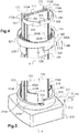
- the pole 170 as shown on the figures 1 and 4 , comprises a longitudinal hollow blade 171 provided, along its longitudinal edge, longitudinal side wings 172 which extend on either side of the longitudinal hollow blade 171, substantially perpendicular thereto ( figures 3 and 4 ).
- a lateral groove 172A is formed in the outer face of each lateral wing 172 of the pole 170. This groove 172A extends longitudinally along the pole 170 and opens towards the outside of the pole 170.
- Each groove 172A of the pole 170 extends in the middle of each lateral wing 172.
- Each groove 172A also has a T-section which widens towards its bottom, so that the longitudinal opening defined by the opening of the groove 172A, on the outer face of the side wing 172, is lined with two reentrant wall members 172B ( figure 4 ).
- the internal transverse dimensions of the sleeve formed by the central portion 220 of the spacer element 200 are substantially equal, with a clearance, to the external dimensions of this pole 170, so as to allow the sliding of the pole 170 in the sleeve .
- the pole 170 is connected to a platform 180 provided with means for attachment to a horizontal wall above the floor and preferably to the ceiling (see figure 3 ).
- the platform 180 is a rigid metal plate. More specifically, as shown in figure 3 , this platform 180 comprises a flat H-shaped mounting part on the ceiling, with four fixing lugs 182 extending, on either side of a rigid central trunk, perpendicular to the longitudinal axis. X of the column 100 when the frame 110 and the pole 170 are fixed on this platform 180.
- the fixing lugs 182 each comprise an orifice 181 for the passage of fixing means on the ceiling, such as screws. They are applied against the ceiling.
- This platform 180 also comprises a cooperation part with the pole 170, comprising a tongue 183 which is bent at 90 ° with respect to the rigid central trunk of the fixing part, so as to extend parallel to the longitudinal axis X from column 100 ( figure 3 ) when the frame 110 and the pole 170 are fixed on this platform 180.
- This tongue 183 is inserted into the longitudinal hollow blade 171 of perch 170 ( Figures 1 to 4 ).
- zones 184 in relief are adapted to cooperate with the pole 170 to guide the tongue 183 in the longitudinal hollow blade 171.
- the support device of the column preferably comprises an adjustable height portion along the longitudinal axis of the column.
- the column 100 comprises for example a squeezable portion, adapted to be reversibly compressed, which is interposed between the front end of the pole and the ceiling.
- This compressible part allows easy support of the column between the two walls chosen, and rapid adaptation of the height of the column to the distance separating these two walls.
- This compressible part may include any means known to those skilled in the art. It may especially be a compression spring or another type of spring, for example a leaf spring, one or more spring washers or one or more corrugated washers, for example of the Ondufil® spring washer type inverted turns. It may also be a rubber ring of the Silentbloc® type, or an element comprising an air cushion, in particular an air cylinder.
- a compression spring or another type of spring for example a leaf spring, one or more spring washers or one or more corrugated washers, for example of the Ondufil® spring washer type inverted turns. It may also be a rubber ring of the Silentbloc® type, or an element comprising an air cushion, in particular an air cylinder.
- a compression spring 190 is interposed between the front end of the pole 170, facing the ceiling, and the ceiling.
- the compression spring 190 is interposed between the fixing portion of the platform 180 and the front end of the pole 170. It is for this purpose threaded around the portion of the tongue 183 of the plate 180 which protrudes out of pole 170.
- the support device of the column 100 comprises a first cam surface 301 integral with said framework 110, a second cam surface 302 associated with said pole 170, and a locking ring 330 arranged to cooperate with the first and second cam surfaces 301, 302 to move the boom 170 relative to the frame 110 upon rotation of said locking ring 330 about the longitudinal axis X of the column 100 (see figure 3 ).
- this arrangement allows simplification of manufacture and implementation of the support device by avoiding the cooperation of threaded surfaces and eliminating tedious screwing / unscrewing steps.
- said first camming surface 301 belongs to a first ring 310 secured to a cover 311 which caps the front end of the frame 110 through which the pole 170 projects.
- the lid 311 forms a single piece with the first ring 310.
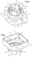
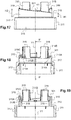
- the lid 311 is shown more particularly on the figures 5 , 8 , 9 and 15 to 19 .
- the lid 311 has a front plate 312 whose shape is similar to that of the section of the frame 110, that is to say substantially square, surrounded at the rear by a falling side wall 313 that comes to apply around the outer face of the front end of the frame 110.
- the front plate 312 of the lid 311 has a central opening 314 circular allowing the passage of the pole 170 ( Figures 15 and 16 ).
- This central opening 314 of central axis Y1 is bordered at the front by the first ring 310 which, as a whole, rises substantially perpendicular to the front plate 312 and has an end free edge forming the cam surface 301.
- this first ring 310 is made in practice by a cylindrical double wall comprising an outer wall 310A and an inner wall 310B concentric around the central axis Y1.
- the outer wall 310A rises from the front plate 312, parallel to the central axis Y1.
- the inner wall 310B extends inside the outer wall 310A.
- the two outer walls 310A and inner 310B have a height, measured along the central axis Y1, variable and are connected by an intermediate wall 310C which forms the free end portion of the first ring 310, the outer face forms the first cam surface 301.
- This first cam surface therefore has an annular shape.
- the central axis Y1 of its central opening 314 coincides with the longitudinal axis X of the column 100.
- the first cam surface 301 is then turned forward.
- This first cam surface 301 forms two half-turns of a first helix winding around said central axis Y1. It thus has a generally helical shape on at least a portion of its circumference. The first cam surface thus extends around the central axis Y1 and on a non-zero height along this central axis Y1.
- the first cam surface 301 rises continuously from a first height H1 to a second height H2 on the contour of the first ring 310 corresponding to a half turn, ie 180 °.
- the first cam surface 301 then comprises a first right step to fall suddenly from the second height H2 to the first height H1.
- This first cam surface 301 then rises again continuously from the first height H1 to the second height H2 on the contour of the first ring 310 corresponding to the other half-turn, ie 180 °, in the same direction. course.
- the first cam surface 301 then comprises a second right step to fall suddenly from the second height H2 to the first height H1.
- the latter carries a stud 319 ( figure 5 ) which protrudes forwardly when the lid 311 is attached to the front end of the frame 110 ( figures 5 and 8 ).
- Each pin 314A is adapted to cooperate with the lateral grooves 172A formed in each lateral wing 172 of the pole 170 (FIG. figure 5 ).
- each pin 314A is partially housed in the lateral groove 172A of the pole 170 so as to slide in the longitudinal opening of this lateral groove 172A when the pole 170 slides in the central portion 220 of the spacers 200 of the frame 110.
- the inner face of the inner wall 310B, turned towards the central opening 314 of the first ring 310 forms a shoulder 318 ( figure 19 ).
- Each tab 315 forms a cylindrical wall portion which extends in the extension of the inner wall 310B of the first ring 310.
- Each tab 315 comprises a longitudinal edge provided with a longitudinal rib 314B which projects inwardly of the first ring 310, parallel to the pin 314A (see figures 9 , 15 and 16 ).
- the two ribs 314B of a pair of legs 315 surround one of the lateral wings 172 of pole 170. They participate in guiding the sliding of the pole 170.
- the first ring 310 is fixed via the lid 311 to the end of the frame 110 and is integral therewith: it can not pivot or slide relative to this frame 110. It is thus locked in pivoting and in sliding on the frame 110.
- Said second cam surface 302 belongs to a second ring 320 mounted on said pole 170.
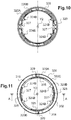
- the second ring 320 is represented more particularly on the figures 4 , 6 , 7 , 10 to 14 .
- This second ring 320 is made in practice by a cylindrical double wall comprising an outer wall 320A and an inner wall 320B concentric around a central axis Y2 of this second ring 320 ( Figures 13 and 14 ). Both outer 320A and inner 320B walls are connected by an intermediate wall 320C which forms the edge of the second ring 320 and whose outer face forms the second cam surface 302.
- This second cam surface therefore has an annular shape.
- the outer wall 320A is delimited between a first rear circular edge forming the base of the second ring 320 and extending in a plane perpendicular to the central axis Y2, and the intermediate wall 320C which carries the second cam surface 302.
- the second cam surface 302 is then turned rearward. It extends vis-à-vis the first cam surface 301.
- This second cam surface 302 forms two half-turns of a second helix winding around said central axis Y2 ( Figures 12 to 14 ).
- the second cam surface thus extends around the central axis Y2 and on a non-zero height along this central axis Y2.
- said inner walls 320B and outer walls 320A have a variable height, measured along the central axis Y2.
- the second cam surface 302 continuously rises from a third height H3 to a fourth height H4 when following the contour of the second ring 320 corresponding to a half turn, ie 180 °.
- the second cam surface 302 then comprises a first right step to fall suddenly from the fourth height H4 at the third height H3.
- This second cam surface 302 then rises again continuously from the third height H3 to the fourth height H4 on the contour of the ring corresponding to the other half-turn, ie 180 °, traveled in the same direction .
- the second cam surface 302 then comprises a second right step to fall suddenly from the fourth height H4 to the third height H3 ( figure 12 ).
- the latter carries a stud 329 ( figures 4 and 12 ) which protrudes rearwardly when the second ring is attached to the pole 170.
- These lugs 325 form a cylindrical wall portion which extends in the extension of the inner wall 320B of the second ring 320.
- ribs 324B which project inwardly from the second ring 320, in length parallel to the central axis Y2 and in height parallel to a diameter of the second ring 320. These ribs 324B are arranged to frame the lateral wing 172 of the pole 170 when it passes through the second ring 320, similarly to the ribs 314B of the first ring 310 ( figure 4 ).
- first and second rings 310, 320 are respectively in place on the frame 110 and the pole 170, they are arranged such that the first and second steps of the first and second cam surfaces 301, 302 face each other.
- said first and second cam surfaces 301, 302 are wound in opposite directions from the same angular position around the longitudinal axis X of the column 100.
- the propellers of the first and second cam surfaces 301, 302 are identical in the direction of the winding close.
- the outer walls 310A, 320A are identical.
- the first and third heights H1 and H3 are equal, and the second and fourth heights H2 and H4 are equal.
- the first and second cam surfaces 301, 302 are the mirror images of each other.
- the respective dimensions of the tabs 315, 325 of the first and second rings 310, 320 are such that they interlock with each other when the two rings 310, 320 are mounted on the frame 110 and the pole 170. They are joined together and together form a cylindrical wall.
- the respective heights of the tabs 315 of the first ring 310 and the tabs 325 of the second ring 320, along the central axes Y1, Y2 of the two rings 310, 320, are such that these tabs remain at least partially nested within each other during the rotation of the locking ring 330.
- the longitudinal edges of the tabs 315, 325 of the first and second rings 310, 320 bear against each other to prevent any rotation of the second ring 320 relative to the first ring 310.
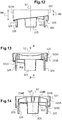
- the second ring 320 further comprises means of cooperation with the pole 170, in the form of a flange 340.
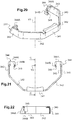
- This flange 340 is more particularly represented on the figures 3 , 4 , 20, 21 and 22 .
- the flange is made of steel.
- It is in the form of a metal strip shaped so as to be inserted into a cylindrical groove 326 of the second ring 320 delimited between the outer 320A and inner 320B walls of the second ring 320.
- the flange 340 extends generally along a semicircle. It presents here more precisely the shape of a half-octagon. Here, it is a semi-base octagonal cylinder and central axis Y3. It thus comprises a central segment 341, two intermediate segments 342 disposed around the central segment 341 as well as two end segments 343. These different segments extend in parallel planes parallel to the central axis Y3.
- the two end segments 343 extend at rest substantially parallel to each other. They further comprise, at their free end, a return 344 folded towards the inside of the flange 340, in the form of a hook.
- the return 344 includes a first portion 344A which extends in a plane substantially perpendicular to the end segment 343, inclined relative to the central axis Y3, and a second portion 344B folded towards the central segment 341 of the flange 340. From this second portion 344B extends, in the direction of the end segment 343 carrying the return 344, a tip 345.
- the inner wall 320B of the second ring 320 furthermore comprises two diametrically opposed slots 327 ( figures 4 , 6 , 7 , 10 and 11 ).
- the cylindrical groove 326 formed between the outer walls 320A and inner 320B of the second ring 320 thus communicates with the central opening of the second ring 320 through these slots 327.
- Each slot 327 is located midway between the guide ribs 324B which extend from the inner face of the inner wall 320B facing the central opening of the second ring 320.
- each slot 327 extends vis-à-vis one of the lateral grooves 172A of the lateral wings 172 of the pole 170.
- the returns 344 pass through the slots 327, so that the second portion 344B of this return 344, provided with the tip 345, extends into outside the cylindrical groove 326, and is housed in the lateral groove 172A of the pole 170 ( figure 4 ).
- the tips 345 are hooked on the internal faces of the reentrant walls 172B of the lateral groove 172A.
- the tips 345 of the steel flange 340 scratch the inner faces of the pole 170 aluminum.
- the flange 340 thus forms a stop for the second ring 320, whose sliding along the pole 170 towards its front end is blocked by the flange 340.
- the second ring 320 is thus locked forwardly sliding and pivoting around of the pole 170.
- the second ring can be fixedly mounted on the pole by any means known to those skilled in the art. It can for example be screwed on the pole.
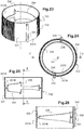
- the locking ring 330 is more particularly represented on the Figures 23 to 26 .
- This ring comprises a cylindrical sleeve 331 of central axis Y4, adapted to surround said first and second rings 310, 320 when the locking ring 330 is mounted on the column 100.
- the central axis Y4 of the sleeve 331 coincides with the longitudinal axis X of the column 100 when the latter is attached to said column 100.
- the inner face 331B of the sleeve 331 oriented towards the central axis Y4 bears in relief and in facing relation, that is to say diametrically opposed, at least two elements of cooperation with said first and second cam surfaces.
- a greater number of cooperation elements distributed regularly along the inner face 331B of the sleeve 331 could be provided, for example three or four cooperation elements.
- the shape of the cam surfaces is then adjusted accordingly, for example three-thirds of a helix revolution or four-quarters of a helix revolution.
- Each cooperation element comprises two opposite bearing surfaces, arranged at a non-zero distance from each other along the central axis Y4 of the sleeve 331, parallel to this central axis Y4 and arranged each in contact with one of said cam surfaces.
- Each cooperation element may optionally comprise two distinct reliefs each carrying one of these bearing surfaces.
- the inner face 331B of the sleeve 331 oriented towards the central axis Y4 bears in relief and vis-à-vis two uprights 336 parallel to each other and parallel to the central axis Y4. They extend over part of the height of the inner face 331B of the sleeve 331. These amounts 336 here constitute said elements of cooperation.
- Each upright 336 has two opposite ends adapted to bear respectively on the first and second cam surfaces 301, 302 of the first and second rings 310, 320 when the locking ring 330 is mounted on the column 100, between said first and second rings 310, 320.
- the opposite ends of the uprights 336 have for this purpose a rounded shape. They constitute said bearing surfaces of the cooperation elements constituted by the amounts.
- the two uprights 336 are connected by a rib 334 which extends on the circumference of the inner face 331B of the sleeve 331.
- This rib has here a T-shape ( figure 25 and 26 ).
- the sleeve 331 also bears here, on its outer face 331A, two raised ribs 333 which are positioned in line with the uprights 336 carried by the inner face 331B of the sleeve 331. These ribs 333 facilitate the manipulation of the locking ring 330 by the installer and constitute visual references of the position of the uprights 336 of the inner face 331B of the sleeve 331.
- the outer face 331A of the sleeve 331 also comprises grooves 332 which extend longitudinally, that is to say according to a direction parallel to the central axis Y4 of the locking ring 330.
- the ridges 332 are located on two diametrically opposed zones of the outer face 331A of the sleeve 331, each covering an angular sector of about 100 ° and they extend over the entire height of the locking ring 330. They improve the grip of hand of the locking ring 330 by the installer (see figure 23 ).
- said first and second rings 310, 320 are here respectively fixed on the frame 110 and associated the pole 170 so that the locations of the first and second rings 310, 320 where the height of the outer wall 310A, 320A is minimum or maximum face each other ( figure 3 ).
- the difference between the first and second cam surfaces 301, 302 thus varies between a minimum distance, at the locations where the outer walls 310A, 320A of the two rings 310, 320 have a maximum height H2, H4, and a maximum gap, places where the outer walls 310A, 320A of the two rings 310, 320 have a minimum height H1, H3.
- each post 336 The rounded surfaces of the opposite ends of each post 336 are in contact with the cam surfaces 301, 302.
- the first and second rings 310, 320 are then, along the longitudinal axis X, as close as possible to one another.
- the second ring 320 is locked between the locking ring 330 and the flange 340, in contact with these two elements.
- the pole 170 is in a low position, in which the length of the pole 170 protruding from the frame is the smallest, and the compression spring 190 is relaxed (see figure 1 ).
- the second ring 320 in abutment against the flange 340 fixed on the perch 170, carries with it the pole 170, which slides in the frame 110 so as to deviate from this frame 110, and move closer to the ceiling or the support wall if it is different from the ceiling.
- the pole 170 is then secured to the second ring 320 when it is moved forward, that is to say towards the support wall.
- the pole 170 and the second ring 320 are fast sliding forward.
- the maximum spacing distance of the pole 170 relative to the frame 110 during the pivoting of the locking ring 330 is equal to the sum of the differences between H2 and H1, on the one hand, and between H3 and H4, d 'somewhere else.
- this spacing distance is 18 millimeters, each difference in height between H2 and H1, on the one hand, and between H3 and H4, on the other hand, being equal to 9 millimeters.
- the pole 170 At the end of the stroke of the locking ring 330, in a second angular position of the locking ring corresponding to the figure 2 , the pole 170 is in a high position, in which the length of the pole protruding from the frame is the largest, and the compression spring 190 is compressed ( figure 2 ).
- the length of the boom 170 projecting from the frame 110 is increased by the spacing distance defined above.
- the angular travel of the locking ring 330 is limited by the abutment of the opposite ends of each upright 336 with the pads 319, 329 facing each other.
- the angular amplitude of pivoting of the locking ring 330 is here limited to 170 °.
- the pivoting stroke of the locking ring may be limited to an angle value of between 80 and 170 °.
- the different elements of the column 100 are positioned relative to each other and the frame 110 is assembled.
- the cover 311 is attached to the front end of the frame 110, the pole 170 is inserted into the frame 110 via the central opening 314 of the first ring 310.
- the ring of 330 and the second ring 320 comprising the flange 340.
- These elements of the bearing device 300 are positioned vertically relative to each other so that, in the first angular position of the locking ring 330, the spring of compression 190 is relaxed.
- the installer pulls the pole 170 until the platform 180 is in contact with the ceiling, then he fixes the second ring 320 on the pole 170 by means of the flange 340.
- the flange 340 is positioned on the pole 170 as a function of the height between the front end of the frame 110 and the support wall of the column 100, so as to block the second ring 320 between the locking ring 330 and the flange 340 in the first angular position.
- the pole 170 is secured to the second ring 320, in particular, integral in pivoting and sliding.
- the installer only has to manually enter the locking ring 330 and rotate it by 170 ° clockwise.
- the installer unlocks the fastener by rotating the locking ring by 170 ° counter-clockwise.
- the spring 190 relaxes and the column 100 can be disassembled.
- the pole 170 is then secured to the second ring 320 sliding backwards, that is to say towards the ground, because of the weight of the pole 170.
- the assembly of the support device 300 can be masked by an unrepresented false ceiling arriving touching the front end of the frame 110.
- the installer may optionally attach the platform 180 to the ceiling, as well as the foot of the column on the floor (not shown).
- the column according to the invention can extend between any two walls.
- the column has a shape parallelepipedic with a base of any quadrilateral shape, for example hexagonal or octagonal and that the frame of the column has more than two cheeks, for example three or four cheeks, defining between them more than two ducts, for example three or four ducts.
Landscapes
- Engineering & Computer Science (AREA)
- Architecture (AREA)
- Civil Engineering (AREA)
- Structural Engineering (AREA)
- Mutual Connection Of Rods And Tubes (AREA)
- Clamps And Clips (AREA)
- Installation Of Indoor Wiring (AREA)
Applications Claiming Priority (1)
| Application Number | Priority Date | Filing Date | Title |
|---|---|---|---|
| FR1662925A FR3060883B1 (fr) | 2016-12-20 | 2016-12-20 | Colonne pour le support d’au moins un appareillage electrique et/ou le cheminement de cables |
Publications (2)
| Publication Number | Publication Date |
|---|---|
| EP3340407A1 true EP3340407A1 (de) | 2018-06-27 |
| EP3340407B1 EP3340407B1 (de) | 2020-08-19 |
Family
ID=58501546
Family Applications (1)
| Application Number | Title | Priority Date | Filing Date |
|---|---|---|---|
| EP17207343.9A Active EP3340407B1 (de) | 2016-12-20 | 2017-12-14 | Säule als halterung für mindestens ein elektrogerät und/oder den kabelkanal |
Country Status (3)
| Country | Link |
|---|---|
| EP (1) | EP3340407B1 (de) |
| ES (1) | ES2822374T3 (de) |
| FR (1) | FR3060883B1 (de) |
Cited By (1)
| Publication number | Priority date | Publication date | Assignee | Title |
|---|---|---|---|---|
| CN114156797A (zh) * | 2021-11-10 | 2022-03-08 | 国网冀北电力有限公司张家口供电公司 | 一种电缆防护装置 |
Citations (4)
| Publication number | Priority date | Publication date | Assignee | Title |
|---|---|---|---|---|
| EP0828326A2 (de) * | 1996-08-29 | 1998-03-11 | Tehalit GmbH | Energiesäule |
| FR2824430A1 (fr) * | 2001-05-04 | 2002-11-08 | Vinco Amenagement | Element de support pour la reception de cables electriques |
| WO2006034513A1 (en) * | 2004-09-20 | 2006-03-30 | Raymond Mazzullo | Power supply system |
| DE102008001461A1 (de) * | 2008-04-29 | 2009-11-12 | Hoff, Alwin, Dipl.-Ing. (FH) | Befestigungssockel für Energiesäulen oder Stehleuchten |
-
2016
- 2016-12-20 FR FR1662925A patent/FR3060883B1/fr not_active Expired - Fee Related
-
2017
- 2017-12-14 ES ES17207343T patent/ES2822374T3/es active Active
- 2017-12-14 EP EP17207343.9A patent/EP3340407B1/de active Active
Patent Citations (4)
| Publication number | Priority date | Publication date | Assignee | Title |
|---|---|---|---|---|
| EP0828326A2 (de) * | 1996-08-29 | 1998-03-11 | Tehalit GmbH | Energiesäule |
| FR2824430A1 (fr) * | 2001-05-04 | 2002-11-08 | Vinco Amenagement | Element de support pour la reception de cables electriques |
| WO2006034513A1 (en) * | 2004-09-20 | 2006-03-30 | Raymond Mazzullo | Power supply system |
| DE102008001461A1 (de) * | 2008-04-29 | 2009-11-12 | Hoff, Alwin, Dipl.-Ing. (FH) | Befestigungssockel für Energiesäulen oder Stehleuchten |
Cited By (2)
| Publication number | Priority date | Publication date | Assignee | Title |
|---|---|---|---|---|
| CN114156797A (zh) * | 2021-11-10 | 2022-03-08 | 国网冀北电力有限公司张家口供电公司 | 一种电缆防护装置 |
| CN114156797B (zh) * | 2021-11-10 | 2023-12-12 | 国网冀北电力有限公司张家口供电公司 | 一种电缆防护装置 |
Also Published As
| Publication number | Publication date |
|---|---|
| FR3060883A1 (fr) | 2018-06-22 |
| EP3340407B1 (de) | 2020-08-19 |
| ES2822374T3 (es) | 2021-04-30 |
| FR3060883B1 (fr) | 2019-05-17 |
Similar Documents
| Publication | Publication Date | Title |
|---|---|---|
| EP2511421A1 (de) | Moduläre Sicherheitsabsperrbarriere mit Schnellmontagesystem | |
| EP3957817B1 (de) | Rollladenstruktur und montageverfahren | |
| FR2984029A1 (fr) | Structure de support d'un appareil electrique de commande ou de protection electrique d'une cellule electrique moyenne tension | |
| EP3340407B1 (de) | Säule als halterung für mindestens ein elektrogerät und/oder den kabelkanal | |
| EP0223680A2 (de) | Hänger für Unterdecke | |
| FR3115809A1 (fr) | Support d’arbre de volet roulant, installation de fermeture ou de protection solaire comprenant un tel support et procédé d’assemblage associé | |
| EP2456032B1 (de) | Vorrichtung zum Verstauen von Stromkabeln | |
| WO2015075361A1 (fr) | Support d'appareillage comportant un accessoire de griffage pour sa fixation a une boite murale, accessoire de griffage, ensemble de griffage et appareillage électrique associes | |
| FR3017498A1 (fr) | Appareillage electrique a encastrer | |
| EP0791552B1 (de) | Spule zum Abwickeln von Wicklungen aus Schläuchen, Profilen oder dergleichen, insbesondere aus Kunststoffmaterial | |
| EP2715894B1 (de) | Zugangsklappe für elektrogeräte | |
| EP2515391B1 (de) | Mehrfachgeräteblock, der mit einem verschiebbaren Zubehörteil ausgestattet ist | |
| EP0958640B1 (de) | Mast zur verticalen Positionierung zwischen Boden und Decke, insbesondere um den Netzzugang eines Arbeitsplatzes sicherzustellen, und Verfahren zur Positionierung eines derartigen Masts | |
| FR2954683A1 (fr) | Presentoir d'exposition et/ou de rangement | |
| WO2011012778A2 (fr) | Boîte électrique de sol à moyens de montage rapide d'un module de connexion électrique | |
| EP2320532B1 (de) | Vorrichtung zur Montage eines Pfostens am hinteren Teil eines Stromverteilungskastens, und mit einer solchen Vorrichtung ausgestatteter Stromverteilungskasten | |
| EP2422416B1 (de) | Höheneinstellbare bodendose | |
| EP2456031A1 (de) | Elektrische Installation, die ein verschiebbares Gerät in einer Wandöffnung enthält | |
| FR2579686A1 (fr) | Dispositif d'assemblage d'un profil bandeau avec un autre element tel qu'un autre profil perpendiculaire ou un element d'accrochage | |
| FR2886930A1 (fr) | Touret comportant une poignee de portage | |
| FR3070712A1 (fr) | Dispositif motorise de manœuvre destine a la manœuvre d'un ecran mobile a toile enroulable d'un dispositif de couverture de fenetre ou d'ecran de projection | |
| FR2758349A1 (fr) | Structure pour cloison amovible | |
| FR2757694A1 (fr) | Dispositif de verrouillage pour la mise en place d'une perche de distribution electrique, et perche de distribution ainsi verrouillee | |
| EP2434598A1 (de) | Elektrisches verschiebbares Zubehör, das in eine Wandöffnung eingebaut ist | |
| EP2341589A1 (de) | Vorrichtung zur Montage eines Gehäuseständers am hinteren Teil eines Stromverteilungskastens, und mit einer solchen Vorrichtung ausgestatteter Stromverteilungskasten |
Legal Events
| Date | Code | Title | Description |
|---|---|---|---|
| PUAI | Public reference made under article 153(3) epc to a published international application that has entered the european phase |
Free format text: ORIGINAL CODE: 0009012 |
|
| STAA | Information on the status of an ep patent application or granted ep patent |
Free format text: STATUS: THE APPLICATION HAS BEEN PUBLISHED |
|
| AK | Designated contracting states |
Kind code of ref document: A1 Designated state(s): AL AT BE BG CH CY CZ DE DK EE ES FI FR GB GR HR HU IE IS IT LI LT LU LV MC MK MT NL NO PL PT RO RS SE SI SK SM TR |
|
| AX | Request for extension of the european patent |
Extension state: BA ME |
|
| STAA | Information on the status of an ep patent application or granted ep patent |
Free format text: STATUS: REQUEST FOR EXAMINATION WAS MADE |
|
| 17P | Request for examination filed |
Effective date: 20181122 |
|
| RBV | Designated contracting states (corrected) |
Designated state(s): AL AT BE BG CH CY CZ DE DK EE ES FI FR GB GR HR HU IE IS IT LI LT LU LV MC MK MT NL NO PL PT RO RS SE SI SK SM TR |
|
| GRAP | Despatch of communication of intention to grant a patent |
Free format text: ORIGINAL CODE: EPIDOSNIGR1 |
|
| STAA | Information on the status of an ep patent application or granted ep patent |
Free format text: STATUS: GRANT OF PATENT IS INTENDED |
|
| RIC1 | Information provided on ipc code assigned before grant |
Ipc: H02G 3/04 20060101AFI20200304BHEP |
|
| INTG | Intention to grant announced |
Effective date: 20200319 |
|
| GRAS | Grant fee paid |
Free format text: ORIGINAL CODE: EPIDOSNIGR3 |
|
| GRAA | (expected) grant |
Free format text: ORIGINAL CODE: 0009210 |
|
| STAA | Information on the status of an ep patent application or granted ep patent |
Free format text: STATUS: THE PATENT HAS BEEN GRANTED |
|
| AK | Designated contracting states |
Kind code of ref document: B1 Designated state(s): AL AT BE BG CH CY CZ DE DK EE ES FI FR GB GR HR HU IE IS IT LI LT LU LV MC MK MT NL NO PL PT RO RS SE SI SK SM TR |
|
| REG | Reference to a national code |
Ref country code: CH Ref legal event code: EP |
|
| REG | Reference to a national code |
Ref country code: DE Ref legal event code: R096 Ref document number: 602017021867 Country of ref document: DE |
|
| REG | Reference to a national code |
Ref country code: AT Ref legal event code: REF Ref document number: 1305043 Country of ref document: AT Kind code of ref document: T Effective date: 20200915 |
|
| REG | Reference to a national code |
Ref country code: IE Ref legal event code: FG4D Free format text: LANGUAGE OF EP DOCUMENT: FRENCH |
|
| REG | Reference to a national code |
Ref country code: LT Ref legal event code: MG4D |
|
| REG | Reference to a national code |
Ref country code: NL Ref legal event code: MP Effective date: 20200819 |
|
| PG25 | Lapsed in a contracting state [announced via postgrant information from national office to epo] |
Ref country code: PT Free format text: LAPSE BECAUSE OF FAILURE TO SUBMIT A TRANSLATION OF THE DESCRIPTION OR TO PAY THE FEE WITHIN THE PRESCRIBED TIME-LIMIT Effective date: 20201221 Ref country code: LT Free format text: LAPSE BECAUSE OF FAILURE TO SUBMIT A TRANSLATION OF THE DESCRIPTION OR TO PAY THE FEE WITHIN THE PRESCRIBED TIME-LIMIT Effective date: 20200819 Ref country code: HR Free format text: LAPSE BECAUSE OF FAILURE TO SUBMIT A TRANSLATION OF THE DESCRIPTION OR TO PAY THE FEE WITHIN THE PRESCRIBED TIME-LIMIT Effective date: 20200819 Ref country code: BG Free format text: LAPSE BECAUSE OF FAILURE TO SUBMIT A TRANSLATION OF THE DESCRIPTION OR TO PAY THE FEE WITHIN THE PRESCRIBED TIME-LIMIT Effective date: 20201119 Ref country code: GR Free format text: LAPSE BECAUSE OF FAILURE TO SUBMIT A TRANSLATION OF THE DESCRIPTION OR TO PAY THE FEE WITHIN THE PRESCRIBED TIME-LIMIT Effective date: 20201120 Ref country code: NO Free format text: LAPSE BECAUSE OF FAILURE TO SUBMIT A TRANSLATION OF THE DESCRIPTION OR TO PAY THE FEE WITHIN THE PRESCRIBED TIME-LIMIT Effective date: 20201119 Ref country code: SE Free format text: LAPSE BECAUSE OF FAILURE TO SUBMIT A TRANSLATION OF THE DESCRIPTION OR TO PAY THE FEE WITHIN THE PRESCRIBED TIME-LIMIT Effective date: 20200819 Ref country code: FI Free format text: LAPSE BECAUSE OF FAILURE TO SUBMIT A TRANSLATION OF THE DESCRIPTION OR TO PAY THE FEE WITHIN THE PRESCRIBED TIME-LIMIT Effective date: 20200819 |
|
| REG | Reference to a national code |
Ref country code: AT Ref legal event code: MK05 Ref document number: 1305043 Country of ref document: AT Kind code of ref document: T Effective date: 20200819 |
|
| PG25 | Lapsed in a contracting state [announced via postgrant information from national office to epo] |
Ref country code: NL Free format text: LAPSE BECAUSE OF FAILURE TO SUBMIT A TRANSLATION OF THE DESCRIPTION OR TO PAY THE FEE WITHIN THE PRESCRIBED TIME-LIMIT Effective date: 20200819 Ref country code: PL Free format text: LAPSE BECAUSE OF FAILURE TO SUBMIT A TRANSLATION OF THE DESCRIPTION OR TO PAY THE FEE WITHIN THE PRESCRIBED TIME-LIMIT Effective date: 20200819 Ref country code: LV Free format text: LAPSE BECAUSE OF FAILURE TO SUBMIT A TRANSLATION OF THE DESCRIPTION OR TO PAY THE FEE WITHIN THE PRESCRIBED TIME-LIMIT Effective date: 20200819 Ref country code: RS Free format text: LAPSE BECAUSE OF FAILURE TO SUBMIT A TRANSLATION OF THE DESCRIPTION OR TO PAY THE FEE WITHIN THE PRESCRIBED TIME-LIMIT Effective date: 20200819 Ref country code: IS Free format text: LAPSE BECAUSE OF FAILURE TO SUBMIT A TRANSLATION OF THE DESCRIPTION OR TO PAY THE FEE WITHIN THE PRESCRIBED TIME-LIMIT Effective date: 20201219 |
|
| PG25 | Lapsed in a contracting state [announced via postgrant information from national office to epo] |
Ref country code: DK Free format text: LAPSE BECAUSE OF FAILURE TO SUBMIT A TRANSLATION OF THE DESCRIPTION OR TO PAY THE FEE WITHIN THE PRESCRIBED TIME-LIMIT Effective date: 20200819 Ref country code: CZ Free format text: LAPSE BECAUSE OF FAILURE TO SUBMIT A TRANSLATION OF THE DESCRIPTION OR TO PAY THE FEE WITHIN THE PRESCRIBED TIME-LIMIT Effective date: 20200819 Ref country code: RO Free format text: LAPSE BECAUSE OF FAILURE TO SUBMIT A TRANSLATION OF THE DESCRIPTION OR TO PAY THE FEE WITHIN THE PRESCRIBED TIME-LIMIT Effective date: 20200819 Ref country code: SM Free format text: LAPSE BECAUSE OF FAILURE TO SUBMIT A TRANSLATION OF THE DESCRIPTION OR TO PAY THE FEE WITHIN THE PRESCRIBED TIME-LIMIT Effective date: 20200819 Ref country code: EE Free format text: LAPSE BECAUSE OF FAILURE TO SUBMIT A TRANSLATION OF THE DESCRIPTION OR TO PAY THE FEE WITHIN THE PRESCRIBED TIME-LIMIT Effective date: 20200819 |
|
| REG | Reference to a national code |
Ref country code: ES Ref legal event code: FG2A Ref document number: 2822374 Country of ref document: ES Kind code of ref document: T3 Effective date: 20210430 |
|
| REG | Reference to a national code |
Ref country code: DE Ref legal event code: R097 Ref document number: 602017021867 Country of ref document: DE |
|
| PG25 | Lapsed in a contracting state [announced via postgrant information from national office to epo] |
Ref country code: AT Free format text: LAPSE BECAUSE OF FAILURE TO SUBMIT A TRANSLATION OF THE DESCRIPTION OR TO PAY THE FEE WITHIN THE PRESCRIBED TIME-LIMIT Effective date: 20200819 Ref country code: AL Free format text: LAPSE BECAUSE OF FAILURE TO SUBMIT A TRANSLATION OF THE DESCRIPTION OR TO PAY THE FEE WITHIN THE PRESCRIBED TIME-LIMIT Effective date: 20200819 |
|
| PLBE | No opposition filed within time limit |
Free format text: ORIGINAL CODE: 0009261 |
|
| STAA | Information on the status of an ep patent application or granted ep patent |
Free format text: STATUS: NO OPPOSITION FILED WITHIN TIME LIMIT |
|
| PG25 | Lapsed in a contracting state [announced via postgrant information from national office to epo] |
Ref country code: SK Free format text: LAPSE BECAUSE OF FAILURE TO SUBMIT A TRANSLATION OF THE DESCRIPTION OR TO PAY THE FEE WITHIN THE PRESCRIBED TIME-LIMIT Effective date: 20200819 |
|
| 26N | No opposition filed |
Effective date: 20210520 |
|
| REG | Reference to a national code |
Ref country code: CH Ref legal event code: PL |
|
| PG25 | Lapsed in a contracting state [announced via postgrant information from national office to epo] |
Ref country code: SI Free format text: LAPSE BECAUSE OF FAILURE TO SUBMIT A TRANSLATION OF THE DESCRIPTION OR TO PAY THE FEE WITHIN THE PRESCRIBED TIME-LIMIT Effective date: 20200819 Ref country code: MC Free format text: LAPSE BECAUSE OF FAILURE TO SUBMIT A TRANSLATION OF THE DESCRIPTION OR TO PAY THE FEE WITHIN THE PRESCRIBED TIME-LIMIT Effective date: 20200819 |
|
| PG25 | Lapsed in a contracting state [announced via postgrant information from national office to epo] |
Ref country code: LU Free format text: LAPSE BECAUSE OF NON-PAYMENT OF DUE FEES Effective date: 20201214 Ref country code: IE Free format text: LAPSE BECAUSE OF NON-PAYMENT OF DUE FEES Effective date: 20201214 |
|
| PG25 | Lapsed in a contracting state [announced via postgrant information from national office to epo] |
Ref country code: LI Free format text: LAPSE BECAUSE OF NON-PAYMENT OF DUE FEES Effective date: 20201231 Ref country code: CH Free format text: LAPSE BECAUSE OF NON-PAYMENT OF DUE FEES Effective date: 20201231 |
|
| PG25 | Lapsed in a contracting state [announced via postgrant information from national office to epo] |
Ref country code: TR Free format text: LAPSE BECAUSE OF FAILURE TO SUBMIT A TRANSLATION OF THE DESCRIPTION OR TO PAY THE FEE WITHIN THE PRESCRIBED TIME-LIMIT Effective date: 20200819 Ref country code: MT Free format text: LAPSE BECAUSE OF FAILURE TO SUBMIT A TRANSLATION OF THE DESCRIPTION OR TO PAY THE FEE WITHIN THE PRESCRIBED TIME-LIMIT Effective date: 20200819 Ref country code: CY Free format text: LAPSE BECAUSE OF FAILURE TO SUBMIT A TRANSLATION OF THE DESCRIPTION OR TO PAY THE FEE WITHIN THE PRESCRIBED TIME-LIMIT Effective date: 20200819 |
|
| PG25 | Lapsed in a contracting state [announced via postgrant information from national office to epo] |
Ref country code: MK Free format text: LAPSE BECAUSE OF FAILURE TO SUBMIT A TRANSLATION OF THE DESCRIPTION OR TO PAY THE FEE WITHIN THE PRESCRIBED TIME-LIMIT Effective date: 20200819 |
|
| GBPC | Gb: european patent ceased through non-payment of renewal fee |
Effective date: 20211214 |
|
| PG25 | Lapsed in a contracting state [announced via postgrant information from national office to epo] |
Ref country code: GB Free format text: LAPSE BECAUSE OF NON-PAYMENT OF DUE FEES Effective date: 20211214 |
|
| P01 | Opt-out of the competence of the unified patent court (upc) registered |
Effective date: 20230519 |
|
| PGFP | Annual fee paid to national office [announced via postgrant information from national office to epo] |
Ref country code: DE Payment date: 20251126 Year of fee payment: 9 |
|
| PGFP | Annual fee paid to national office [announced via postgrant information from national office to epo] |
Ref country code: IT Payment date: 20251119 Year of fee payment: 9 |
|
| PGFP | Annual fee paid to national office [announced via postgrant information from national office to epo] |
Ref country code: FR Payment date: 20251119 Year of fee payment: 9 |
|
| PGFP | Annual fee paid to national office [announced via postgrant information from national office to epo] |
Ref country code: BE Payment date: 20251119 Year of fee payment: 9 |
|
| PGFP | Annual fee paid to national office [announced via postgrant information from national office to epo] |
Ref country code: ES Payment date: 20260102 Year of fee payment: 9 |