EP3340407B1 - Säule als halterung für mindestens ein elektrogerät und/oder den kabelkanal - Google Patents
Säule als halterung für mindestens ein elektrogerät und/oder den kabelkanal Download PDFInfo
- Publication number
- EP3340407B1 EP3340407B1 EP17207343.9A EP17207343A EP3340407B1 EP 3340407 B1 EP3340407 B1 EP 3340407B1 EP 17207343 A EP17207343 A EP 17207343A EP 3340407 B1 EP3340407 B1 EP 3340407B1
- Authority
- EP
- European Patent Office
- Prior art keywords
- column
- pole
- frame
- ring
- longitudinal axis
- Prior art date
- Legal status (The legal status is an assumption and is not a legal conclusion. Google has not performed a legal analysis and makes no representation as to the accuracy of the status listed.)
- Active
Links
Images


Classifications
-
- H—ELECTRICITY
- H02—GENERATION; CONVERSION OR DISTRIBUTION OF ELECTRIC POWER
- H02G—INSTALLATION OF ELECTRIC CABLES OR LINES, OR OF COMBINED OPTICAL AND ELECTRIC CABLES OR LINES
- H02G3/00—Installations of electric cables or lines or protective tubing therefor in or on buildings, equivalent structures or vehicles
- H02G3/02—Details
- H02G3/04—Protective tubing or conduits, e.g. cable ladders or cable troughs
- H02G3/0493—Service poles
Definitions
- the present invention relates to a column for supporting at least one electrical apparatus and / or the routing of cables or energy transport conductors in accordance with the preamble of claim 1.
- the invention finds a particularly advantageous application for the production of a vertical column to be fixed between the floor and the ceiling of a room.
- Such columns are placed in rooms with a large area, such as open-plan offices, and are held vertically between the floor and the ceiling. They can also be in the form of posts the height of which is such that their top reaches the level of a desk top.
- cables or conductive wires also allow the routing of cables or conductive wires to which said equipment is connected. These cables or conductive wires come from the floor or the ceiling and are received inside these columns in conduits for routing cables or conductive wires.
- the invention proposes a new column comprising a support device that is simple to manufacture and to use by the user.
- the invention relates to a column according to claim 1.
- the front side of the parts described will correspond to the one facing the ceiling and the rear side will correspond to the one facing the floor.
- a column 100 in accordance with the invention for supporting electrical equipment (not shown) and routing the cable or conductors necessary for serving said equipment.
- this column 100 can support all kinds of electrical equipment, including equipment powered by strong current such as sockets and switches, but also equipment powered by low current, such as computer and telephone equipment.
- This column 100 is intended to be supported between two walls. For this purpose, it comprises a device for resting between two walls.
- It can also, for example, be supported between the ground and a horizontal wall such as the horizontal plate of a desk.
- Column 100 comprises a frame 110 elongated along a longitudinal axis X.
- This frame 110 here has a generally parallelepipedal shape, with a substantially square base, with four opposite main faces parallel two by two.
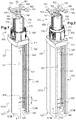
- the support device 300 for this framework 110 comprises in particular a telescopic pole 170 partially housed in said framework 110 and a part of which extends in the extension of said framework 110.
- the pole 170 comprises a lower part slidably housed in the frame 110 and an upper part which projects out of the frame 110 through one end of the frame 110 (see figures 1 to 3 ).
- the pole 170 protrudes through the front end of the frame 110, intended to be oriented towards the ceiling.
- the framework 110 includes at least two cheeks 120 ( figures 1, 2 and 3 ) of elongated shape along the longitudinal axis X, comprising, along their free longitudinal edges 121, mounting means adapted to receive directly or indirectly at least one electrical device housed between said cheeks.
- said mounting means may be adapted to directly receive additional mounting means provided on the base of each device or mounting means of a support intended for mounting such devices.
- the frame 110 further comprises at least two separate spacer elements 200 connecting the cheeks 120 together, the two spacer elements 200 being spaced from one another, along said longitudinal axis, to a distance greater than or equal to the height of one of the spacer elements 200.
- the spacer elements 200 keep the two cheeks 120 together, spaced between them by the same distance equal to the width of the spacer element 200 ( figures 1 and 2 ).
- the spacer elements 200 are formed of distinct and separate individual pieces, arranged at a distance from each other, as mentioned previously.
- the two cheeks 120 delimit, with said spacer elements 200, at least one conduit for housing the electrical equipment (s) as well as the housing of the cables or conductors necessary for serving each equipment.
- each duct is adapted to accommodate a plurality of electrical equipment.
- the cheeks 120 form two opposite main faces of the frame 110 and delimit two conduits which each open onto one of the other two opposite main faces of the frame 110.
- the cheeks 120 thus form the lateral wings delimiting each duct, while the spacer elements 200 form a bottom of these ducts.
- the two conduits are thus here arranged back to back. They each open by a longitudinal opening 140 extending along the longitudinal axis X of the column 100. Each longitudinal opening 140 is delimited by two free edges 121 facing the two cheeks 120 (see figures 1 to 3 ).
- Each of the longitudinal openings 140 of said conduits is intended to be closed by cover sections (here, not shown) which extend between the facades of the electrical equipment attached to the conduits.
- said spacer elements 200 form a discontinuous bottom for the conduits.
- the column 100 has a greater capacity for receiving electrical equipment and electrical cables than the conventional columns already known.
- the two spacer elements 200 of the frame 110 of the column 100 are here each disposed near one of the longitudinal ends of the frame 110.
- One of the two spacer elements 200 is disposed near a first longitudinal end of the column 100, for example its front end intended to be disposed near the ceiling, while the other spacer element 200 is disposed near the other longitudinal end of the column 100, for example its rear end intended to be disposed near the ground.
- a third spacer element can be provided, for example, placed near the middle of the column.
- a plurality of spacer elements can also be provided.
- the maximum number of spacer elements depends on the height of the spacer elements and the total height of the column.
- the spacer elements are preferably distributed regularly along the frame 110, that is to say spaced from each other by the same predetermined distance.
- the framework 110 measures between 50 centimeters and 4 meters in height along the longitudinal axis X, for example approximately 2.5 meters.
- Each spacer element 200 measures a few centimeters in height along the longitudinal axis X.
- each spacer element 200 preferably has a height H measured along the longitudinal axis of the column of between 1 and 20 centimeters, preferably between 2 and 10 centimeters, for example equal to 4 centimeters ( figure 1 ).
- Each cheek 120 has a generally rectangular sidewall 121A, elongated along the longitudinal axis X of column 100.
- Each side 121A here has a slightly arched profile for a purely aesthetic question.
- Each cheek 120 comprises, along the two longitudinal edges of its flank 121A, two parallel returns 121B which extend generally perpendicular to the flank 121A ( figures 1 to 3 ).
- each cheek 120 When the cheeks 120 are connected by the spacer elements 200 (see figure 3 ), the returns 121B of each cheek 120 are oriented towards the inside of the column 100.
- a return 121B of one of the cheeks 120 extends in the direction of a return 121B of the other cheek 120.
- the two free edges 121 of the two vis-à-vis returns 121B define the edges of the longitudinal opening 140 of a duct formed by the frame 110.
- the internal face of the sidewall 121A carries a hooking structure 122 profiled along the longitudinal axis X of the column.
- This attachment structure 122 is used for mounting the cover sections (not shown) to close the longitudinal opening 140 of each duct of the column 100. It is also used for mounting the various electrical equipment (not shown) in the ducts of the column 100. column 100.
- the electrical equipment is mounted on supports snapped onto this hooking structure 122, so that the front of said equipment appears through the longitudinal opening 140 of the duct accommodating the equipment. These devices then locally close this longitudinal opening 140.
- each electrical switchgear mechanism hooks directly to the hooking structure 122.
- the cover sections here, not shown, have an elongated shape and are intended to close the longitudinal openings 140 of the conduits at the places where no electrical equipment is installed. Thus, the four faces of the column 100 are closed and electrical safety is ensured.
- cover sections each comprise a substantially rectangular closure panel provided with snap-fastening means on the attachment structure 122.
- Each cheek 120 also comprises, on its internal face turned towards the inside of the column 100, means for mounting the spacer element 200, adapted to cooperate in retaining with complementary mounting means of each spacer element. 200.
- each spacer element 200 are located on two opposite mounting walls of this spacer element.
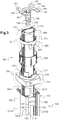
- a central part of the spacer element 200 forms with the mounting walls a sleeve which extends, in the frame 110, along the longitudinal axis X ( figure 3 ).
- the central part here comprises for this purpose two walls extending vis-à-vis, parallel to one another between the two mounting walls.
- This sleeve accommodates the telescopic 170 pole ( figure 3 ) of the support device for the framework 110.
- the pole 170 is more precisely introduced into the sleeve formed by the central part of the spacer element 200 located near the front end of the frame 100, that is to say near the end frame closest to the ceiling.
- the cross section of the sleeve delimited by the central part of the spacer element 200 has for this purpose a shape similar to that of the cross section of the pole 170.
- This cross section here has an H shape.
- the pole 170 as shown in the figures 1 and 4 , comprises a longitudinal hollow blade 171 provided, along its longitudinal edges, longitudinal side wings 172 which extend on either side of the longitudinal hollow blade 171, substantially perpendicular to the latter ( figures 3 and 4 ).
- a lateral groove 172A is formed in the external face of each lateral wing 172 of the pole 170. This groove 172A extends longitudinally along the pole 170 and opens towards the outside of the pole 170.
- Each groove 172A of the pole 170 extends in the middle of each side wing 172.
- Each groove 172A also has a T-section which widens towards its bottom, so that the longitudinal opening delimited by the outlet of the groove 172A, on the external face of the side wing 172, is bordered by two re-entrant wall elements 172B ( figure 4 ).
- the internal transverse dimensions of the sleeve formed by the central part 220 of the spacer element 200 are substantially equal, except for a clearance, to the external dimensions of this pole 170, so as to allow the sliding of the pole 170 in the sleeve. .
- the pole 170 is connected to a platform 180 provided with means allowing its attachment to a horizontal wall located above the ground and advantageously to the ceiling (see figure 3 ).
- the platform 180 is a rigid metal plate. More precisely, as shown in figure 3 , this platform 180 comprises a flat part for fixing to the ceiling, in the shape of an H, with four fixing lugs 182 extending, on either side of a rigid central trunk, perpendicular to the longitudinal axis X of the column 100 when the frame 110 and the pole 170 are fixed on this platform 180.
- the fixing lugs 182 each comprise an orifice 181 for the passage of fixing means on the ceiling, such as screws. They are applied against the ceiling.
- This platform 180 also comprises a part of cooperation with the pole 170, comprising a tongue 183 which is bent at 90 ° relative to the rigid central trunk of the fixing part, so as to extend parallel to the longitudinal axis X of column 100 ( figure 3 ) when the frame 110 and the pole 170 are fixed on this platform 180.
- This tongue 183 is inserted into the longitudinal hollow blade 171 of perch 170 ( figures 1 to 4 ).
- zones 184 in relief are adapted to cooperate with the pole 170 to guide the tongue 183 in the longitudinal hollow blade 171.
- the column supporting device preferably comprises a portion of adjustable height along the longitudinal axis of the column.
- the column 100 comprises for example a compressible part, adapted to be reversibly compressed, which is interposed between the front end of the pole and the ceiling.
- This compressible part allows the column to be easily supported between the two chosen walls, and a rapid adaptation of the height of the column to the distance separating these two walls.
- This compressible part can include any means known to those skilled in the art. It may in particular be a compression spring or another type of spring, for example a leaf spring, one or more spring washers or one or more wave washers, for example of the Ondufil® spring washer type. with inverted turns. It may also be a rubber ring of the Silentbloc® type, or an element comprising an air cushion, in particular an air cylinder.
- a compression spring or another type of spring for example a leaf spring, one or more spring washers or one or more wave washers, for example of the Ondufil® spring washer type. with inverted turns. It may also be a rubber ring of the Silentbloc® type, or an element comprising an air cushion, in particular an air cylinder.
- a compression spring 190 is interposed between the front end of the pole 170, facing the ceiling, and the ceiling.
- the compression spring 190 is interposed between the fixing part of the platform 180 and the front end of the pole 170. It is for this purpose threaded around the part of the tongue 183 of the platform. -form 180 which protrudes out of the pole 170.
- the device for resting the column 100 comprises a first cam surface 301 integral with said frame 110, a second cam surface 302 associated with said pole 170, and a locking ring 330 arranged to cooperate with the first and second cam surfaces 301, 302 in order to move the pole 170 relative to the frame 110 during the rotation of said locking ring 330 about the longitudinal axis X of the column 100 (see figure 3 ).
- this arrangement makes it possible to simplify the manufacture and use of the bearing device by avoiding the cooperation of threaded surfaces and by eliminating tedious screwing / unscrewing steps.
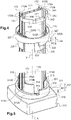
- said first cam surface 301 belongs to a first ring 310 integral with a cover 311 covering the front end of the frame 110 through which the pole 170 projects.
- the cover 311 forms a single piece with the first ring 310.
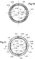
- the cover 311 is shown more particularly on the figures 5 , 8 , 9 and 15 to 19 .
- the cover 311 comprises a front plate 312, the shape of which is similar to that of the section of the frame 110, that is to say substantially square, surrounded at the rear by a falling side wall 313 which is applied. around the outer face of the front end of the frame 110.
- the front plate 312 of the cover 311 has a central circular opening 314 allowing the passage of the pole 170 ( figures 15 and 16 ).
- This central opening 314 of central axis Y1 is bordered at the front by the first ring 310 which, overall, rises substantially perpendicularly to the front plate 312 and has a free end section forming the cam surface 301.
- this first ring 310 is produced in practice by a double cylindrical wall comprising an outer wall 310A and an inner wall 310B concentric around the central axis Y1.
- the outer wall 310A rises from the front plate 312, parallel to the central axis Y1.
- the inner wall 310B extends inside the outer wall 310A.
- the two outer walls 310A and inner 310B have a height, measured along the central axis Y1, variable and are connected by an intermediate wall 310C which forms the free end section of the first ring 310, the external face of which forms the first cam surface 301.
- This first cam surface therefore has an annular shape.
- the central axis Y1 of its central opening 314 coincides with the longitudinal axis X of the column 100. Furthermore, the first cam surface 301 is then facing forward.
- This first cam surface 301 forms two half-turns of a first helix winding around said central axis Y1. It thus has an overall helical shape over at least part of its circumference. The first cam surface thus extends around the central axis Y1 and over a non-zero height along this central axis Y1.
- the first cam surface 301 rises continuously from a first height H1 to a second height H2 on the contour of the first ring 310 corresponding to a half-turn, ie 180 °.
- the first cam surface 301 then comprises a first straight step to drop sharply from the second height H2 to the first height H1.
- This first cam surface 301 then rises again continuously from the first height H1 to the second height H2 on the contour of the first ring 310 corresponding to the other half-turn, ie 180 °, in the same direction of course.
- the first cam surface 301 then comprises a second straight step to drop sharply from the second height H2 to the first height H1.
- Each pin 314A is adapted to cooperate with the lateral grooves 172A formed in each lateral wing 172 of the pole 170 ( figure 5 ).
- each pin 314A is partially housed in the lateral groove 172A of the pole 170, so as to slide in the longitudinal opening of this lateral groove 172A when the pole 170 slides in the central part 220 of the spacers 200 of the frame 110.
- legs 315 extend forward when the cover 311 is attached to the front end of the frame 110.
- Each tab 315 forms a cylindrical wall portion which extends in the extension of the internal wall 310B of the first ring 310.
- Each tab 315 comprises a longitudinal edge provided with a longitudinal rib 314B which projects inwardly. of the first ring 310, parallel to the pin 314A (see figures 9 , 15 and 16 ).
- the two ribs 314B of a pair of tabs 315 frame one of the side wings 172 of the pole 170. They participate in guiding the sliding of the pole 170.
- the first ring 310 is fixed via the cover 311 to the end of the frame 110 and is integral with the latter: it can neither pivot nor slide relative to this frame 110. It is therefore locked in pivoting and in sliding on the frame 110.
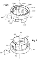
- Said second cam surface 302 belongs to a second ring 320 mounted on said pole 170.
- the second ring 320 is shown more particularly on the figures 4 , 6 , 7 , 10 to 14 .
- This second ring 320 is produced in practice by a cylindrical double wall comprising an outer wall 320A and an inner wall 320B concentric about a central axis Y2 of this second ring 320 ( figures 13 and 14 ).
- the two outer walls 320A and inner 320B are connected by an intermediate wall 320C which forms the edge of the second ring 320 and whose outer face forms the second cam surface 302.
- This second cam surface therefore has an annular shape.
- the outer wall 320A is delimited between a first rear circular edge forming the base of the second ring 320 and extending in a plane perpendicular to the central axis Y2, and the intermediate wall 320C which carries the second cam surface 302.
- the second cam surface 302 is then turned rearward. It extends vis-à-vis the first cam surface 301.
- This second cam surface 302 forms two half-turns of a second helix winding around said central axis Y2 ( figures 12 to 14 ).
- the second cam surface thus extends around the central axis Y2 and over a non-zero height along this central axis Y2.
- Said internal 320B and external 320A walls have for this purpose a variable height, measured along the central axis Y2.
- the second cam surface 302 rises continuously from a third height H3 to a fourth height H4 when following the contour of the second ring 320 corresponding to a half-turn, ie 180 °.
- the second cam surface 302 then includes a first straight step to drop sharply from the fourth height H4 to the third height H3.
- This second cam surface 302 then rises again continuously from the third height H3 to the fourth height H4 on the contour of the ring corresponding to the other half-turn, ie 180 °, traveled in the same direction .
- the second cam surface 302 then includes a second straight step to drop sharply from the fourth height H4 to the third height H3 ( figure 12 ).
- the latter carries a stud 329 ( figures 4 and 12 ) which protrudes backwards when the second ring is attached to the pole 170.
- These tabs 325 form a cylindrical wall portion which extends in the extension of the internal wall 320B of the second ring 320.
- ribs 324B which project inwardly from the second ring 320, lengthwise parallel to the central axis Y2. and in height parallel to a diameter of the second ring 320.
- These ribs 324B are arranged so as to frame the side wing 172 of the pole 170 when the latter passes through the second ring 320, in a similar manner to the ribs 314B of the first ring 310 ( figure 4 ).
- first and second rings 310, 320 are respectively in place on the frame 110 and the pole 170, they are arranged so that the first and second steps of the first and second cam surfaces 301, 302 face each other.
- first and second cam surfaces 301, 302 wind in opposite directions, from the same angular position around the longitudinal axis X of column 100.
- the helices of the first and second cam surfaces 301, 302 are identical except for the direction of winding.
- the outer walls 310A, 320A are identical.
- the first and third heights H1 and H3 are equal, and the second and fourth heights H2 and H4 are equal.
- the first and second cam surfaces 301, 302 are here mirror images of one another.
- the respective dimensions of the legs 315, 325 of the first and second rings 310, 320 are such that they fit into each other when the two rings 310, 320 are mounted on the frame 110 and the pole 170. They are contiguous and together form a cylindrical wall.
- the respective heights of the legs 315 of the first ring 310 and of the legs 325 of the second ring 320, along the central axes Y1, Y2 of the two rings 310, 320, are such that these legs remain at least partially nested in each other during of the rotation of the locking ring 330.
- the longitudinal edges of the tabs 315, 325 of the first and second rings 310, 320 bear against each other to prevent any rotation of the second ring 320 relative to the first ring 310.
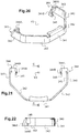
- the second ring 320 further comprises means of cooperation with the pole 170, in the form of a flange 340.
- This flange 340 is more particularly shown in the figures. figures 3 , 4 , 20, 21 and 22 .
- the flange is made of steel.
- It is in the form of a metal strip shaped so as to be able to be inserted into a cylindrical groove 326 of the second ring 320, delimited between the outer walls 320A and inner 320B of this second ring 320.
- the flange 340 extends generally along a semicircle. It has here more precisely the shape of a half-octagon. Here, it is an octagonal base half cylinder with a central axis Y3. It thus comprises a central segment 341, two intermediate segments 342 arranged around the central segment 341 as well as two end segments 343. These different segments extend along mean planes parallel to the central axis Y3.
- the two end segments 343 extend at rest substantially parallel to one another. They further include, at their free end, a return 344 folded towards the inside of the flange 340, in the form of a hook.
- the return 344 comprises a first part 344A which extends in a plane substantially perpendicular to the end segment 343, inclined with respect to the central axis Y3, and a second part 344B folded towards the central segment 341 of the flange 340. From this second part 344B extends, in the direction of the end segment 343 carrying the return 344, a point 345.
- the internal wall 320B of the second ring 320 further comprises here two diametrically opposed slots 327 ( figures 4 , 6 , 7 , 10 and 11 ).
- the cylindrical groove 326 formed between the outer 320A and inner 320B walls of the second ring 320 therefore communicates with the central opening of the second ring 320 through these slots 327.
- Each slot 327 is located midway between the guide ribs 324B which extend from the internal face of the internal wall 320B facing towards the central opening of the second ring 320.
- each slot 327 extends opposite one of the lateral grooves 172A of the lateral wings 172 of the pole 170.
- the returns 344 pass through the slots 327, so that the second part 344B of this return 344, provided with the point 345, extends in outside the cylindrical groove 326, and fits into the lateral groove 172A of the pole 170 ( figure 4 ).
- the points 345 hook onto the internal faces of the re-entrant walls 172B of the lateral groove 172A.
- the spikes 345 of the steel flange 340 claw the internal faces of the aluminum pole 170.
- the flange 340 thus forms a stop for the second ring 320, the sliding of which along the pole 170 towards its front end is blocked by the flange 340.
- the second ring 320 is thus blocked in sliding forward and in pivoting around. perch 170.
- the second ring can be fixedly mounted on the pole by any means known to those skilled in the art. It can for example be screwed onto the pole.
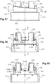
- the locking ring 330 is more particularly shown on the figures 23 to 26 .
- This ring comprises a cylindrical sleeve 331 with a central axis Y4, adapted to surround said first and second rings 310, 320 when the locking ring 330 is mounted on the column 100.
- the central axis Y4 of the sleeve 331 coincides with the longitudinal axis X of the column 100 when the latter is attached to said column 100.
- the internal face 331B of the sleeve 331 oriented towards the central axis Y4 bears in relief and facing each other, that is to say diametrically opposed, at least two elements of cooperation with said first and second cam surfaces.
- the shape of the cam surfaces is then adjusted accordingly, for example three-thirds of a propeller turn or four-quarter turn of the propeller.
- Each cooperation element comprises two opposite bearing surfaces, arranged at a non-zero distance from one another along the central axis Y4 of the sleeve 331, parallel to this central axis Y4 and arranged each in contact with one of said cam surfaces.
- Each cooperation element may optionally include two distinct reliefs each carrying one of these bearing surfaces.
- the internal face 331B of the sleeve 331 oriented towards the central axis Y4 bears in relief and facing each other two uprights 336 mutually parallel and parallel to the central axis Y4. They extend over part of the height of the internal face 331B of the sleeve 331.
- These uprights 336 here constitute said cooperation elements.
- Each upright 336 has two opposite ends adapted to rest respectively on the first and second cam surfaces 301, 302 of the first and second rings 310, 320 when the locking ring 330 is mounted on the column 100, between said first and second rings 310, 320.
- the opposite ends of the uprights 336 have a rounded shape for this purpose. They constitute said bearing surfaces of the cooperation elements constituted by the uprights.
- the two uprights 336 are connected by a rib 334 which extends around the circumference of the internal face 331B of the sleeve 331.
- This rib has a T-shape here ( figure 25 and 26 ).
- the sleeve 331 also carries here, on its external face 331A, two ribs 333 in relief which are positioned in line with the uprights 336 carried by the internal face 331B of the sleeve 331. These ribs 333 facilitate the handling of the locking ring 330 by the installer and constitute visual cues of the position of the uprights 336 of the internal face 331B of the sleeve 331.
- the external face 331A of the sleeve 331 also comprises ridges 332 which extend longitudinally, that is to say in a direction parallel to the central axis Y4 of the locking ring 330.
- the ridges 332 are located on two diametrically opposed zones of the external face 331A of the sleeve 331, each covering an angular sector of approximately 100 ° and they extend over the entire height of the locking ring 330. They improve the grip. hand of the locking ring 330 by the installer (see figure 23 ).
- said first and second rings 310, 320 are here respectively fixed on the frame 110 and associated the pole 170 so that the places of the first and second rings 310, 320 where the height of the outer wall 310A, 320A is minimum or maximum face each other ( figure 3 ).
- the gap between the first and second cam surfaces 301, 302 therefore varies between a minimum gap, at the locations where the outer walls 310A, 320A of the two rings 310, 320 have a maximum height H2, H4, and a maximum gap, at the locations places where the outer walls 310A, 320A of the two rings 310, 320 have a minimum height H1, H3.
- the uprights 336 are housed between the first and second cam surfaces 301, 302, at the places where the gap between the cam surfaces 301, 302 is maximum.
- each post 336 contact the cam surfaces 301, 302.
- the pads 319, 329 projecting from the cam surfaces 301, 302 then come in pairs in abutment against one another and the free end of the rear legs 325 of the second ring 320 rests on the shoulder 318 of the internal wall 310B of the first ring 310.
- the first and second rings 310, 320 are then, along the longitudinal axis X, as close as possible to one another.
- the second ring 320 is blocked between the locking ring 330 and the flange 340, in contact with these two elements.
- the pole 170 is in a low position, in which the length of the pole 170 projecting out of the frame is the smallest, and the compression spring 190 is relaxed (see figure 1 ).
- the second ring 320 in abutment against the flange 340 fixed on the pole 170, carries with it the pole 170, which slides in the frame 110 so as to move away from this frame 110, and approach the ceiling or the support wall if the latter is different from the ceiling.
- the pole 170 is then integral with the second ring 320 when the latter is moved forward, that is to say towards the support wall.
- the pole 170 and the second ring 320 are integral in sliding forward.
- the maximum distance between the pole 170 and the frame 110 when pivoting the locking ring 330 is equal to the sum of the differences between H2 and H1, on the one hand, and between H3 and H4, d 'somewhere else.
- this separation distance is 18 millimeters, each height difference between H2 and H1, on the one hand, and between H3 and H4, on the other hand, being equal to 9 millimeters.
- the pole 170 At the end of the travel of the locking ring 330, in a second angular position of the locking ring corresponding to the figure 2 , the pole 170 is in a high position, in which the length of the pole projecting out of the frame is the greatest, and the compression spring 190 is compressed ( figure 2 ). The length of the pole 170 projecting from the frame 110 is increased by the spacing distance defined above.
- the angular travel of the locking ring 330 is limited by the abutment of the opposite ends of each upright 336 with the studs 319, 329 facing each other.
- the angular amplitude of pivoting of the locking ring 330 is thus here limited to 170 °.
- the pivoting stroke of the locking ring can be limited to an angle value of between 80 and 170 °.
- the different elements of the column 100 are positioned relative to each other and the framework 110 is assembled.
- the cover 311 is attached to the front end of the frame 110, the pole 170 is inserted into the frame 110, via the central opening 314 of the first ring 310.
- the locking 330 and the second ring 320 comprising the flange 340.
- These elements of the resting device 300 are positioned vertically with respect to each other such that, in the first angular position of the locking ring 330, the spring of compression 190 is relaxed.
- the installer pulls the pole 170 until the platform 180 is in contact with the ceiling, then he fixes the second ring 320 on the pole 170 by means of the flange 340.
- the flange 340 is positioned on the pole 170 as a function of the height between the front end of the frame 110 and the support wall of the column 100, so as to block the second ring 320 between the locking ring 330 and the flange 340 in the first angular position.
- the pole 170 is integral with the second ring 320, in particular, integral in pivoting and sliding.
- the installer only has to manually grab the locking ring 330 and turn it 170 ° clockwise.
- the installer unlocks its fixing by turning the locking ring 170 ° counterclockwise.
- the spring 190 relaxes and the column 100 can be dismantled.
- the pole 170 is then secured to the second ring 320 sliding rearwardly, that is to say towards the ground, due to the weight of the pole 170.
- the whole of the bearing device 300 can be masked by a false ceiling, not shown, which comes in contact with the front end of the frame 110.
- the installer can optionally fix the platform 180 to the ceiling, as well as the foot of the column to the ground (not shown).
- the column according to the invention can extend between any two walls.
- the column can have a shape parallelepiped with a base of any quadrilateral shape, for example hexagonal or octagonal and that the framework of the column has more than two cheeks, for example three or four cheeks, delimiting between them more than two conduits, for example three or four conduits.
Landscapes
- Engineering & Computer Science (AREA)
- Architecture (AREA)
- Civil Engineering (AREA)
- Structural Engineering (AREA)
- Mutual Connection Of Rods And Tubes (AREA)
- Clamps And Clips (AREA)
- Installation Of Indoor Wiring (AREA)
Claims (9)
- Säule (100) als Halterung für mindestens ein Elektrogerät und/oder den Kanal für Kabel oder Leiter für den Transport von Energie, die sich entlang einer Längsachse (X) erstreckt und ein längliches Gerüst (110), das wenigstens einen Kanal begrenzt, und eine Vorrichtung (300) zum Einklemmen des Gerüsts (110) zwischen zwei Wandungen aufweist, die eine Teleskopstange (170) aufweist, wobei die Vorrichtung (300) zum Einklemmen eine mit dem Gerüst (110) fest verbundene erste Nockenfläche (301) und eine zur Stange (170) gehörende zweite Nockenfläche (302) aufweist, wobei die erste und die zweite Nockenfläche ringförmig sind,
dadurch gekennzeichnet, daß die Teleskopstange (170) teilweise im Gerüst (110) angeordnet ist und sich ein Teil davon in Verlängerung des Gerüsts (110) erstreckt, und die Vorrichtung (300) zum Einklemmen einen Verriegelungsring (330) aufweist, der auf einer Innenseite zwei zur Längsachse (X) der Säule (100) parallele Nasen (336) aufweist, deren gegenüberliegende Enden dazu ausgelegt sind, gegen die erste (301) und zweite (302) Nockenfläche zu drücken, um die Stange (170) bei der Drehung des Verriegelungsrings (330) um die Längsachse (X) der Säule (100) gegenüber dem Gerüst (110) zu bewegen. - Säule (100) gemäß Anspruch 1, bei der die erste Nockenfläche (301) zu einem ersten Ring (310) gehört, der mit einem Deckel (311) fest verbunden ist, der das Ende des Gerüsts (110) abschließt, durch das die Stange (170) hervorragt.
- Säule (100) gemäß einem der Ansprüche 1 und 2, bei der die zweite Nockenfläche (302) zu einem an der Stange (170) befestigten zweiten Ring (320) gehört.
- Säule (100) gemäß einem der Ansprüche 1 bis 3, bei der die erste Nockenfläche (301) zwei Hälften eines sich um die Längsachse (X) windenden ersten Gewindegangs bildet.
- Säule (100) gemäß einem der Ansprüche 1 bis 4, bei der die zweite Nockenfläche (302) zwei Hälften eines sich um die Längsachse (X) windenden zweiten Gewindegangs bildet.
- Säule (100) gemäß den Ansprüchen 4 und 5, bei der sich der erste und der zweite Gewindegang von einer selben Winkelposition aus in entgegengesetzten Richtungen um die Längsachse (X) der Säule (100) erstrecken.
- Säule (100) gemäß einem der vorangehenden Ansprüche, bei der die gegenüberliegenden Enden jeder Nase (336) dazu ausgelegt sind, auf der ersten und der zweiten Nockenfläche (301, 302) zu gleiten, wenn der Verriegelungsring (330) um die Längsachse (X) der Säule (100) schwenkt.
- Säule (100) gemäß einem der vorangehenden Ansprüche, bei der auf der ersten und der zweiten Nockenfläche (301, 302) einander gegenüberliegende Erhebungen (319, 329) vorgesehen sind, die dazu ausgelegt sind, mit dem Verriegelungsring (330) zusammenzuwirken, um dessen Winkelbewegung zu begrenzen.
- Säule (100) gemäß einem der vorangehenden Ansprüche, bei der die Vorrichtung (300) zum Einklemmen außerdem eine Druckfeder (190) aufweist, die dazu bestimmt ist, zwischen dem freien Ende der Teleskopstange (170) und einer der Wandungen, zwischen denen die Säule (100) eingeklemmt ist, zu liegen.
Applications Claiming Priority (1)
| Application Number | Priority Date | Filing Date | Title |
|---|---|---|---|
| FR1662925A FR3060883B1 (fr) | 2016-12-20 | 2016-12-20 | Colonne pour le support d’au moins un appareillage electrique et/ou le cheminement de cables |
Publications (2)
| Publication Number | Publication Date |
|---|---|
| EP3340407A1 EP3340407A1 (de) | 2018-06-27 |
| EP3340407B1 true EP3340407B1 (de) | 2020-08-19 |
Family
ID=58501546
Family Applications (1)
| Application Number | Title | Priority Date | Filing Date |
|---|---|---|---|
| EP17207343.9A Active EP3340407B1 (de) | 2016-12-20 | 2017-12-14 | Säule als halterung für mindestens ein elektrogerät und/oder den kabelkanal |
Country Status (3)
| Country | Link |
|---|---|
| EP (1) | EP3340407B1 (de) |
| ES (1) | ES2822374T3 (de) |
| FR (1) | FR3060883B1 (de) |
Families Citing this family (1)
| Publication number | Priority date | Publication date | Assignee | Title |
|---|---|---|---|---|
| CN114156797B (zh) * | 2021-11-10 | 2023-12-12 | 国网冀北电力有限公司张家口供电公司 | 一种电缆防护装置 |
Family Cites Families (4)
| Publication number | Priority date | Publication date | Assignee | Title |
|---|---|---|---|---|
| DE29615033U1 (de) * | 1996-08-29 | 1998-01-02 | Tehalit GmbH, 67716 Heltersberg | Energiesäule |
| FR2824430B1 (fr) * | 2001-05-04 | 2003-06-13 | Vinco Amenagement | Element de support pour la reception de cables electriques |
| WO2006034513A1 (en) * | 2004-09-20 | 2006-03-30 | Raymond Mazzullo | Power supply system |
| DE102008001461B4 (de) * | 2008-04-29 | 2017-04-06 | Alwin Hoff | Befestigungssockel für Energiesäulen oder Stehleuchten |
-
2016
- 2016-12-20 FR FR1662925A patent/FR3060883B1/fr not_active Expired - Fee Related
-
2017
- 2017-12-14 ES ES17207343T patent/ES2822374T3/es active Active
- 2017-12-14 EP EP17207343.9A patent/EP3340407B1/de active Active
Non-Patent Citations (1)
| Title |
|---|
| None * |
Also Published As
| Publication number | Publication date |
|---|---|
| FR3060883A1 (fr) | 2018-06-22 |
| ES2822374T3 (es) | 2021-04-30 |
| EP3340407A1 (de) | 2018-06-27 |
| FR3060883B1 (fr) | 2019-05-17 |
Similar Documents
| Publication | Publication Date | Title |
|---|---|---|
| FR3000308A1 (fr) | Module d'appareillage electrique amovible, boite electrique d'accueil d'un tel module d'appareillage et procede de remplacement d'un tel module d'appareillage | |
| EP0224290A1 (de) | Bauart einer abdeckbaren Bedachung | |
| EP3340407B1 (de) | Säule als halterung für mindestens ein elektrogerät und/oder den kabelkanal | |
| FR2984029A1 (fr) | Structure de support d'un appareil electrique de commande ou de protection electrique d'une cellule electrique moyenne tension | |
| EP2017211B1 (de) | Vorrichtung zum Abwickeln von aufgewickelten Kabelrollen | |
| EP0223680A2 (de) | Hänger für Unterdecke | |
| FR3115809A1 (fr) | Support d’arbre de volet roulant, installation de fermeture ou de protection solaire comprenant un tel support et procédé d’assemblage associé | |
| EP0791552B1 (de) | Spule zum Abwickeln von Wicklungen aus Schläuchen, Profilen oder dergleichen, insbesondere aus Kunststoffmaterial | |
| EP3095350A1 (de) | Vorrichtung zum einhängen eines paneels in eine tragstruktur | |
| EP2515391B1 (de) | Mehrfachgeräteblock, der mit einem verschiebbaren Zubehörteil ausgestattet ist | |
| EP0290335A1 (de) | Aufwickelvorrichtung, insbesondere für elektrische Kabel | |
| EP2715894B1 (de) | Zugangsklappe für elektrogeräte | |
| EP2515390B1 (de) | Mehrfachgeräteblock, der mit Mitteln zur Befestigung an der Wand ausgestattet ist | |
| EP2456031B1 (de) | Elektrische Installation, die ein verschiebbares Gerät in einer Wandöffnung enthält | |
| FR2954683A1 (fr) | Presentoir d'exposition et/ou de rangement | |
| FR3043853A1 (fr) | Bague de reception d'une boite electrique a encastrer dans une paroi murale | |
| EP2422416B1 (de) | Höheneinstellbare bodendose | |
| EP0958640A1 (de) | Versorgungssäule | |
| FR2620754A1 (fr) | Poteau pour la realisation de clotures | |
| BE886570A (fr) | Escalier a pas variables. | |
| FR2579686A1 (fr) | Dispositif d'assemblage d'un profil bandeau avec un autre element tel qu'un autre profil perpendiculaire ou un element d'accrochage | |
| FR2757694A1 (fr) | Dispositif de verrouillage pour la mise en place d'une perche de distribution electrique, et perche de distribution ainsi verrouillee | |
| EP2434599A1 (de) | Elektrisches verschiebbares Zubehör, das in eine Wandöffnung eingebaut ist | |
| FR2758349A1 (fr) | Structure pour cloison amovible | |
| FR3033604A1 (fr) | Systeme de deux profiles associes pour ossature |
Legal Events
| Date | Code | Title | Description |
|---|---|---|---|
| PUAI | Public reference made under article 153(3) epc to a published international application that has entered the european phase |
Free format text: ORIGINAL CODE: 0009012 |
|
| STAA | Information on the status of an ep patent application or granted ep patent |
Free format text: STATUS: THE APPLICATION HAS BEEN PUBLISHED |
|
| AK | Designated contracting states |
Kind code of ref document: A1 Designated state(s): AL AT BE BG CH CY CZ DE DK EE ES FI FR GB GR HR HU IE IS IT LI LT LU LV MC MK MT NL NO PL PT RO RS SE SI SK SM TR |
|
| AX | Request for extension of the european patent |
Extension state: BA ME |
|
| STAA | Information on the status of an ep patent application or granted ep patent |
Free format text: STATUS: REQUEST FOR EXAMINATION WAS MADE |
|
| 17P | Request for examination filed |
Effective date: 20181122 |
|
| RBV | Designated contracting states (corrected) |
Designated state(s): AL AT BE BG CH CY CZ DE DK EE ES FI FR GB GR HR HU IE IS IT LI LT LU LV MC MK MT NL NO PL PT RO RS SE SI SK SM TR |
|
| GRAP | Despatch of communication of intention to grant a patent |
Free format text: ORIGINAL CODE: EPIDOSNIGR1 |
|
| STAA | Information on the status of an ep patent application or granted ep patent |
Free format text: STATUS: GRANT OF PATENT IS INTENDED |
|
| RIC1 | Information provided on ipc code assigned before grant |
Ipc: H02G 3/04 20060101AFI20200304BHEP |
|
| INTG | Intention to grant announced |
Effective date: 20200319 |
|
| GRAS | Grant fee paid |
Free format text: ORIGINAL CODE: EPIDOSNIGR3 |
|
| GRAA | (expected) grant |
Free format text: ORIGINAL CODE: 0009210 |
|
| STAA | Information on the status of an ep patent application or granted ep patent |
Free format text: STATUS: THE PATENT HAS BEEN GRANTED |
|
| AK | Designated contracting states |
Kind code of ref document: B1 Designated state(s): AL AT BE BG CH CY CZ DE DK EE ES FI FR GB GR HR HU IE IS IT LI LT LU LV MC MK MT NL NO PL PT RO RS SE SI SK SM TR |
|
| REG | Reference to a national code |
Ref country code: CH Ref legal event code: EP |
|
| REG | Reference to a national code |
Ref country code: DE Ref legal event code: R096 Ref document number: 602017021867 Country of ref document: DE |
|
| REG | Reference to a national code |
Ref country code: AT Ref legal event code: REF Ref document number: 1305043 Country of ref document: AT Kind code of ref document: T Effective date: 20200915 |
|
| REG | Reference to a national code |
Ref country code: IE Ref legal event code: FG4D Free format text: LANGUAGE OF EP DOCUMENT: FRENCH |
|
| REG | Reference to a national code |
Ref country code: LT Ref legal event code: MG4D |
|
| REG | Reference to a national code |
Ref country code: NL Ref legal event code: MP Effective date: 20200819 |
|
| PG25 | Lapsed in a contracting state [announced via postgrant information from national office to epo] |
Ref country code: PT Free format text: LAPSE BECAUSE OF FAILURE TO SUBMIT A TRANSLATION OF THE DESCRIPTION OR TO PAY THE FEE WITHIN THE PRESCRIBED TIME-LIMIT Effective date: 20201221 Ref country code: LT Free format text: LAPSE BECAUSE OF FAILURE TO SUBMIT A TRANSLATION OF THE DESCRIPTION OR TO PAY THE FEE WITHIN THE PRESCRIBED TIME-LIMIT Effective date: 20200819 Ref country code: HR Free format text: LAPSE BECAUSE OF FAILURE TO SUBMIT A TRANSLATION OF THE DESCRIPTION OR TO PAY THE FEE WITHIN THE PRESCRIBED TIME-LIMIT Effective date: 20200819 Ref country code: BG Free format text: LAPSE BECAUSE OF FAILURE TO SUBMIT A TRANSLATION OF THE DESCRIPTION OR TO PAY THE FEE WITHIN THE PRESCRIBED TIME-LIMIT Effective date: 20201119 Ref country code: GR Free format text: LAPSE BECAUSE OF FAILURE TO SUBMIT A TRANSLATION OF THE DESCRIPTION OR TO PAY THE FEE WITHIN THE PRESCRIBED TIME-LIMIT Effective date: 20201120 Ref country code: NO Free format text: LAPSE BECAUSE OF FAILURE TO SUBMIT A TRANSLATION OF THE DESCRIPTION OR TO PAY THE FEE WITHIN THE PRESCRIBED TIME-LIMIT Effective date: 20201119 Ref country code: SE Free format text: LAPSE BECAUSE OF FAILURE TO SUBMIT A TRANSLATION OF THE DESCRIPTION OR TO PAY THE FEE WITHIN THE PRESCRIBED TIME-LIMIT Effective date: 20200819 Ref country code: FI Free format text: LAPSE BECAUSE OF FAILURE TO SUBMIT A TRANSLATION OF THE DESCRIPTION OR TO PAY THE FEE WITHIN THE PRESCRIBED TIME-LIMIT Effective date: 20200819 |
|
| REG | Reference to a national code |
Ref country code: AT Ref legal event code: MK05 Ref document number: 1305043 Country of ref document: AT Kind code of ref document: T Effective date: 20200819 |
|
| PG25 | Lapsed in a contracting state [announced via postgrant information from national office to epo] |
Ref country code: NL Free format text: LAPSE BECAUSE OF FAILURE TO SUBMIT A TRANSLATION OF THE DESCRIPTION OR TO PAY THE FEE WITHIN THE PRESCRIBED TIME-LIMIT Effective date: 20200819 Ref country code: PL Free format text: LAPSE BECAUSE OF FAILURE TO SUBMIT A TRANSLATION OF THE DESCRIPTION OR TO PAY THE FEE WITHIN THE PRESCRIBED TIME-LIMIT Effective date: 20200819 Ref country code: LV Free format text: LAPSE BECAUSE OF FAILURE TO SUBMIT A TRANSLATION OF THE DESCRIPTION OR TO PAY THE FEE WITHIN THE PRESCRIBED TIME-LIMIT Effective date: 20200819 Ref country code: RS Free format text: LAPSE BECAUSE OF FAILURE TO SUBMIT A TRANSLATION OF THE DESCRIPTION OR TO PAY THE FEE WITHIN THE PRESCRIBED TIME-LIMIT Effective date: 20200819 Ref country code: IS Free format text: LAPSE BECAUSE OF FAILURE TO SUBMIT A TRANSLATION OF THE DESCRIPTION OR TO PAY THE FEE WITHIN THE PRESCRIBED TIME-LIMIT Effective date: 20201219 |
|
| PG25 | Lapsed in a contracting state [announced via postgrant information from national office to epo] |
Ref country code: DK Free format text: LAPSE BECAUSE OF FAILURE TO SUBMIT A TRANSLATION OF THE DESCRIPTION OR TO PAY THE FEE WITHIN THE PRESCRIBED TIME-LIMIT Effective date: 20200819 Ref country code: CZ Free format text: LAPSE BECAUSE OF FAILURE TO SUBMIT A TRANSLATION OF THE DESCRIPTION OR TO PAY THE FEE WITHIN THE PRESCRIBED TIME-LIMIT Effective date: 20200819 Ref country code: RO Free format text: LAPSE BECAUSE OF FAILURE TO SUBMIT A TRANSLATION OF THE DESCRIPTION OR TO PAY THE FEE WITHIN THE PRESCRIBED TIME-LIMIT Effective date: 20200819 Ref country code: SM Free format text: LAPSE BECAUSE OF FAILURE TO SUBMIT A TRANSLATION OF THE DESCRIPTION OR TO PAY THE FEE WITHIN THE PRESCRIBED TIME-LIMIT Effective date: 20200819 Ref country code: EE Free format text: LAPSE BECAUSE OF FAILURE TO SUBMIT A TRANSLATION OF THE DESCRIPTION OR TO PAY THE FEE WITHIN THE PRESCRIBED TIME-LIMIT Effective date: 20200819 |
|
| REG | Reference to a national code |
Ref country code: ES Ref legal event code: FG2A Ref document number: 2822374 Country of ref document: ES Kind code of ref document: T3 Effective date: 20210430 |
|
| REG | Reference to a national code |
Ref country code: DE Ref legal event code: R097 Ref document number: 602017021867 Country of ref document: DE |
|
| PG25 | Lapsed in a contracting state [announced via postgrant information from national office to epo] |
Ref country code: AT Free format text: LAPSE BECAUSE OF FAILURE TO SUBMIT A TRANSLATION OF THE DESCRIPTION OR TO PAY THE FEE WITHIN THE PRESCRIBED TIME-LIMIT Effective date: 20200819 Ref country code: AL Free format text: LAPSE BECAUSE OF FAILURE TO SUBMIT A TRANSLATION OF THE DESCRIPTION OR TO PAY THE FEE WITHIN THE PRESCRIBED TIME-LIMIT Effective date: 20200819 |
|
| PLBE | No opposition filed within time limit |
Free format text: ORIGINAL CODE: 0009261 |
|
| STAA | Information on the status of an ep patent application or granted ep patent |
Free format text: STATUS: NO OPPOSITION FILED WITHIN TIME LIMIT |
|
| PG25 | Lapsed in a contracting state [announced via postgrant information from national office to epo] |
Ref country code: SK Free format text: LAPSE BECAUSE OF FAILURE TO SUBMIT A TRANSLATION OF THE DESCRIPTION OR TO PAY THE FEE WITHIN THE PRESCRIBED TIME-LIMIT Effective date: 20200819 |
|
| 26N | No opposition filed |
Effective date: 20210520 |
|
| REG | Reference to a national code |
Ref country code: CH Ref legal event code: PL |
|
| PG25 | Lapsed in a contracting state [announced via postgrant information from national office to epo] |
Ref country code: SI Free format text: LAPSE BECAUSE OF FAILURE TO SUBMIT A TRANSLATION OF THE DESCRIPTION OR TO PAY THE FEE WITHIN THE PRESCRIBED TIME-LIMIT Effective date: 20200819 Ref country code: MC Free format text: LAPSE BECAUSE OF FAILURE TO SUBMIT A TRANSLATION OF THE DESCRIPTION OR TO PAY THE FEE WITHIN THE PRESCRIBED TIME-LIMIT Effective date: 20200819 |
|
| PG25 | Lapsed in a contracting state [announced via postgrant information from national office to epo] |
Ref country code: LU Free format text: LAPSE BECAUSE OF NON-PAYMENT OF DUE FEES Effective date: 20201214 Ref country code: IE Free format text: LAPSE BECAUSE OF NON-PAYMENT OF DUE FEES Effective date: 20201214 |
|
| PG25 | Lapsed in a contracting state [announced via postgrant information from national office to epo] |
Ref country code: LI Free format text: LAPSE BECAUSE OF NON-PAYMENT OF DUE FEES Effective date: 20201231 Ref country code: CH Free format text: LAPSE BECAUSE OF NON-PAYMENT OF DUE FEES Effective date: 20201231 |
|
| PG25 | Lapsed in a contracting state [announced via postgrant information from national office to epo] |
Ref country code: TR Free format text: LAPSE BECAUSE OF FAILURE TO SUBMIT A TRANSLATION OF THE DESCRIPTION OR TO PAY THE FEE WITHIN THE PRESCRIBED TIME-LIMIT Effective date: 20200819 Ref country code: MT Free format text: LAPSE BECAUSE OF FAILURE TO SUBMIT A TRANSLATION OF THE DESCRIPTION OR TO PAY THE FEE WITHIN THE PRESCRIBED TIME-LIMIT Effective date: 20200819 Ref country code: CY Free format text: LAPSE BECAUSE OF FAILURE TO SUBMIT A TRANSLATION OF THE DESCRIPTION OR TO PAY THE FEE WITHIN THE PRESCRIBED TIME-LIMIT Effective date: 20200819 |
|
| PG25 | Lapsed in a contracting state [announced via postgrant information from national office to epo] |
Ref country code: MK Free format text: LAPSE BECAUSE OF FAILURE TO SUBMIT A TRANSLATION OF THE DESCRIPTION OR TO PAY THE FEE WITHIN THE PRESCRIBED TIME-LIMIT Effective date: 20200819 |
|
| GBPC | Gb: european patent ceased through non-payment of renewal fee |
Effective date: 20211214 |
|
| PG25 | Lapsed in a contracting state [announced via postgrant information from national office to epo] |
Ref country code: GB Free format text: LAPSE BECAUSE OF NON-PAYMENT OF DUE FEES Effective date: 20211214 |
|
| P01 | Opt-out of the competence of the unified patent court (upc) registered |
Effective date: 20230519 |
|
| PGFP | Annual fee paid to national office [announced via postgrant information from national office to epo] |
Ref country code: DE Payment date: 20251126 Year of fee payment: 9 |
|
| PGFP | Annual fee paid to national office [announced via postgrant information from national office to epo] |
Ref country code: IT Payment date: 20251119 Year of fee payment: 9 |
|
| PGFP | Annual fee paid to national office [announced via postgrant information from national office to epo] |
Ref country code: FR Payment date: 20251119 Year of fee payment: 9 |
|
| PGFP | Annual fee paid to national office [announced via postgrant information from national office to epo] |
Ref country code: BE Payment date: 20251119 Year of fee payment: 9 |
|
| PGFP | Annual fee paid to national office [announced via postgrant information from national office to epo] |
Ref country code: ES Payment date: 20260102 Year of fee payment: 9 |