EP3340407A1 - Column for supporting at least one electrical appliance and/or routing of cables - Google Patents
Column for supporting at least one electrical appliance and/or routing of cables Download PDFInfo
- Publication number
- EP3340407A1 EP3340407A1 EP17207343.9A EP17207343A EP3340407A1 EP 3340407 A1 EP3340407 A1 EP 3340407A1 EP 17207343 A EP17207343 A EP 17207343A EP 3340407 A1 EP3340407 A1 EP 3340407A1
- Authority
- EP
- European Patent Office
- Prior art keywords
- column
- ring
- pole
- frame
- longitudinal axis
- Prior art date
- Legal status (The legal status is an assumption and is not a legal conclusion. Google has not performed a legal analysis and makes no representation as to the accuracy of the status listed.)
- Granted
Links
Images


Classifications
-
- H—ELECTRICITY
- H02—GENERATION; CONVERSION OR DISTRIBUTION OF ELECTRIC POWER
- H02G—INSTALLATION OF ELECTRIC CABLES OR LINES, OR OF COMBINED OPTICAL AND ELECTRIC CABLES OR LINES
- H02G3/00—Installations of electric cables or lines or protective tubing therefor in or on buildings, equivalent structures or vehicles
- H02G3/02—Details
- H02G3/04—Protective tubing or conduits, e.g. cable ladders or cable troughs
- H02G3/0493—Service poles
Definitions
- the present invention relates to a column for supporting at least one electrical equipment and / or the routing of cables or conductors for energy transport according to the preamble of claim 1.
- the invention finds a particularly advantageous application for the production of a vertical column to be fixed between the floor and the ceiling of a room.
- Such columns are placed in large areas, such as landscaped offices, and are held vertically between the floor and the ceiling. They can also be in the form of posts whose height is such that their summit reaches the level of an office tray.
- These columns can support electrical equipment such as power outlets, switches, fuse holders, disconnectors, circuit breakers, or computer equipment such as computer jacks, or telephone equipment such as telephone sockets.
- the invention proposes a new column comprising a support device simple to manufacture and implement by the user.
- the invention relates to a column according to claim 1.
- the front side of the parts described will correspond to the one facing the ceiling and the back side will correspond to that facing the floor.
- a column 100 Partially represented, on the Figures 1 and 2 , a column 100 according to the invention for the support of electrical equipment (not shown) and the routing of cable or conductors necessary for the serving of said apparatus.
- this column 100 can support all kinds of electrical equipment, including equipment powered by strong current such as sockets and switches, but also equipment powered by low current, such as computer and telephone equipment.
- This column 100 is intended to be supported between two walls. It comprises for this purpose a support device between two walls.
- This is particularly a vertical column, intended to be placed between the floor and the ceiling of a room.
- It can also for example be placed in abutment between the ground and a horizontal wall such as the horizontal plate of a desk.
- Column 100 comprises a framework 110 elongated along a longitudinal axis X.
- This framework 110 here has a generally parallelepiped shape, substantially square base, with four opposite major faces parallel in pairs.
- the bearing device 300 of this framework 110 comprises in particular a telescopic pole 170 partially housed in said framework 110 and a portion of which extends in the extension of said framework 110.
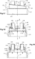
- the pole 170 comprises a lower portion slidably housed in the frame 110 and an upper part which projects out of the frame 110 through one end of the frame 110 (see FIG. Figures 1 to 3 ).
- the pole 170 protrudes through the front end of the frame 110, intended to be oriented towards the ceiling.
- the frame 110 comprises at least two cheeks 120 ( Figures 1, 2 and 3 ) of elongate shape along the longitudinal axis X, having, along their longitudinal free edges 121, mounting means adapted to receive directly or indirectly at least one electrical equipment housed between said cheeks.
- said mounting means may be adapted to directly receive complementary mounting means provided on the base of each apparatus or means for mounting a support for mounting such apparatus.
- the frame 110 further comprises at least two separate spacer members 200 connecting the cheeks 120 to each other, the two spacer members 200 being spaced apart from each other along said longitudinal axis, a distance greater than or equal to the height of one of the spacer elements 200.
- the spacer elements 200 hold the two cheeks 120 together, separated from each other by the same distance equal to the width of the spacer element 200 ( Figures 1 and 2 ).
- the spacer members 200 are formed of discrete and separate individual pieces spaced apart from one another as previously mentioned.
- the two cheeks 120 delimit, with said spacer elements 200, at least one duct for housing the electrical equipment or devices and the housing of cables or conductors necessary for the service of each apparatus.
- each duct is adapted to accommodate a plurality of electrical equipment.
- the cheeks 120 form two opposite main faces of the frame 110 and define two ducts which each open on one of the other two opposite main faces of the frame 110.
- the cheeks 120 thus form the lateral wings delimiting each duct, while the spacer elements 200 form a bottom of these ducts.
- the two ducts are thus here arranged back to back. They open each by a longitudinal opening 140 extending along the longitudinal axis X of the column 100. Each longitudinal opening 140 is delimited by two free edges 121 facing the two cheeks 120 (see FIG. Figures 1 to 3 ).
- Each of the longitudinal openings 140 of said ducts is intended to be closed by cover sections (here, not shown) which extend between the facades of electrical equipment reported in the ducts.
- said spacer members 200 form a discontinuous bottom for the conduits.
- the two ducts communicate with each other.
- the column 100 has a greater capacity for receiving electrical equipment and electrical cables than conventional columns already known.
- the two spacer members 200 of the frame 110 of the column 100 are here each arranged near one of the longitudinal ends of the frame 110.
- One of the two spacer elements 200 is disposed near a first longitudinal end of the column 100, for example its front end intended to be arranged close to the ceiling, while the other spacer element 200 is disposed near the other longitudinal end of the column 100, for example its rear end intended to be disposed close to the ground.
- a third spacer element disposed near the middle of the column.
- the maximum number of spacer members depends on the height of the spacer members and the total height of the column.
- the spacer elements are preferably distributed regularly along the frame 110, that is to say spaced apart from each other by the same predetermined distance.
- the frame 110 is between 50 centimeters and 4 meters high along the longitudinal axis X, for example about 2.5 meters.
- Each spacer element 200 measures a few centimeters in height along the longitudinal axis X.
- each spacer element 200 preferably has a height H measured along the longitudinal axis of the column of between 1 and 20 centimeters, preferably between 2 and 10 centimeters, for example equal to 4 centimeters ( figure 1 ).
- Each flange 120 comprises a generally rectangular flank 121A, elongate along the longitudinal axis X of the column 100.
- Each flank 121A here has a slightly arched profile for a purely aesthetic question.
- Each cheek 120 comprises, along the two longitudinal edges of its flank 121A, two parallel returns 121B which extend generally perpendicularly to the flank 121A ( Figures 1 to 3 ).
- each cheek 120 When the cheeks 120 are connected by the spacer elements 200 (see figure 3 ), the returns 121B of each cheek 120 are oriented towards the inside of the column 100.
- a return 121B of one of the cheeks 120 extends towards a return 121B of the other cheek 120.
- the inner face of the flank 121A carries a fastening structure 122 profiled along the longitudinal axis X of the column.
- This attachment structure 122 serves for mounting the cover sections (not shown) to close the longitudinal opening 140 of each conduit of the column 100. It also serves to mount the various electrical equipment (not shown) in the ducts of the column 100.
- the electrical equipment is mounted on supports latched on this attachment structure 122, so that the front of said apparatus appears through the longitudinal opening 140 of the conduit housing the equipment. These devices then locally close this longitudinal opening 140.
- each electrical equipment mechanism clings directly to the attachment structure 122.
- the lid sections here not shown, have an elongated shape and are intended to close the longitudinal openings 140 ducts where no electrical equipment is installed. Thus, the four faces of the column 100 are closed and the electrical safety is ensured.
- lid sections each comprise a substantially rectangular closure panel provided with latching means on the attachment structure 122.
- Each cheek 120 also comprises, on its internal face turned towards the inside of the column 100, means for mounting the spacer element 200, adapted to cooperate with retention with complementary mounting means of each spacer element 200.
- each spacer member 200 are located on two opposite mounting walls of said spacer member.
- a central part of the spacer element 200 forms with the mounting walls a sleeve which extends, in the frame 110, along the longitudinal axis X ( figure 3 ).
- the central portion here comprises for this purpose two walls extending vis-a-vis, parallel to each other between the two mounting walls.
- This sleeve accommodates the telescopic pole 170 ( figure 3 ) of the support device of the frame 110.
- the pole 170 is more precisely introduced into the sleeve formed by the central part of the spacer element 200 located near the front end of the frame 100, that is to say near the end the frame closest to the ceiling.
- the transverse section of the sleeve delimited by the central part of the spacer element 200 has for this purpose a shape similar to that of the transverse section of the pole 170.
- This transverse section here has a shape in H.
- the pole 170 as shown on the figures 1 and 4 , comprises a longitudinal hollow blade 171 provided, along its longitudinal edge, longitudinal side wings 172 which extend on either side of the longitudinal hollow blade 171, substantially perpendicular thereto ( figures 3 and 4 ).
- a lateral groove 172A is formed in the outer face of each lateral wing 172 of the pole 170. This groove 172A extends longitudinally along the pole 170 and opens towards the outside of the pole 170.
- Each groove 172A of the pole 170 extends in the middle of each lateral wing 172.
- Each groove 172A also has a T-section which widens towards its bottom, so that the longitudinal opening defined by the opening of the groove 172A, on the outer face of the side wing 172, is lined with two reentrant wall members 172B ( figure 4 ).
- the internal transverse dimensions of the sleeve formed by the central portion 220 of the spacer element 200 are substantially equal, with a clearance, to the external dimensions of this pole 170, so as to allow the sliding of the pole 170 in the sleeve .
- the pole 170 is connected to a platform 180 provided with means for attachment to a horizontal wall above the floor and preferably to the ceiling (see figure 3 ).
- the platform 180 is a rigid metal plate. More specifically, as shown in figure 3 , this platform 180 comprises a flat H-shaped mounting part on the ceiling, with four fixing lugs 182 extending, on either side of a rigid central trunk, perpendicular to the longitudinal axis. X of the column 100 when the frame 110 and the pole 170 are fixed on this platform 180.
- the fixing lugs 182 each comprise an orifice 181 for the passage of fixing means on the ceiling, such as screws. They are applied against the ceiling.
- This platform 180 also comprises a cooperation part with the pole 170, comprising a tongue 183 which is bent at 90 ° with respect to the rigid central trunk of the fixing part, so as to extend parallel to the longitudinal axis X from column 100 ( figure 3 ) when the frame 110 and the pole 170 are fixed on this platform 180.
- This tongue 183 is inserted into the longitudinal hollow blade 171 of perch 170 ( Figures 1 to 4 ).
- zones 184 in relief are adapted to cooperate with the pole 170 to guide the tongue 183 in the longitudinal hollow blade 171.
- the support device of the column preferably comprises an adjustable height portion along the longitudinal axis of the column.
- the column 100 comprises for example a squeezable portion, adapted to be reversibly compressed, which is interposed between the front end of the pole and the ceiling.
- This compressible part allows easy support of the column between the two walls chosen, and rapid adaptation of the height of the column to the distance separating these two walls.
- This compressible part may include any means known to those skilled in the art. It may especially be a compression spring or another type of spring, for example a leaf spring, one or more spring washers or one or more corrugated washers, for example of the Ondufil® spring washer type inverted turns. It may also be a rubber ring of the Silentbloc® type, or an element comprising an air cushion, in particular an air cylinder.
- a compression spring or another type of spring for example a leaf spring, one or more spring washers or one or more corrugated washers, for example of the Ondufil® spring washer type inverted turns. It may also be a rubber ring of the Silentbloc® type, or an element comprising an air cushion, in particular an air cylinder.
- a compression spring 190 is interposed between the front end of the pole 170, facing the ceiling, and the ceiling.
- the compression spring 190 is interposed between the fixing portion of the platform 180 and the front end of the pole 170. It is for this purpose threaded around the portion of the tongue 183 of the plate 180 which protrudes out of pole 170.
- the support device of the column 100 comprises a first cam surface 301 integral with said framework 110, a second cam surface 302 associated with said pole 170, and a locking ring 330 arranged to cooperate with the first and second cam surfaces 301, 302 to move the boom 170 relative to the frame 110 upon rotation of said locking ring 330 about the longitudinal axis X of the column 100 (see figure 3 ).
- this arrangement allows simplification of manufacture and implementation of the support device by avoiding the cooperation of threaded surfaces and eliminating tedious screwing / unscrewing steps.
- said first camming surface 301 belongs to a first ring 310 secured to a cover 311 which caps the front end of the frame 110 through which the pole 170 projects.
- the lid 311 forms a single piece with the first ring 310.
- the lid 311 is shown more particularly on the figures 5 , 8 , 9 and 15 to 19 .
- the lid 311 has a front plate 312 whose shape is similar to that of the section of the frame 110, that is to say substantially square, surrounded at the rear by a falling side wall 313 that comes to apply around the outer face of the front end of the frame 110.
- the front plate 312 of the lid 311 has a central opening 314 circular allowing the passage of the pole 170 ( Figures 15 and 16 ).
- This central opening 314 of central axis Y1 is bordered at the front by the first ring 310 which, as a whole, rises substantially perpendicular to the front plate 312 and has an end free edge forming the cam surface 301.
- this first ring 310 is made in practice by a cylindrical double wall comprising an outer wall 310A and an inner wall 310B concentric around the central axis Y1.
- the outer wall 310A rises from the front plate 312, parallel to the central axis Y1.
- the inner wall 310B extends inside the outer wall 310A.
- the two outer walls 310A and inner 310B have a height, measured along the central axis Y1, variable and are connected by an intermediate wall 310C which forms the free end portion of the first ring 310, the outer face forms the first cam surface 301.
- This first cam surface therefore has an annular shape.
- the central axis Y1 of its central opening 314 coincides with the longitudinal axis X of the column 100.
- the first cam surface 301 is then turned forward.
- This first cam surface 301 forms two half-turns of a first helix winding around said central axis Y1. It thus has a generally helical shape on at least a portion of its circumference. The first cam surface thus extends around the central axis Y1 and on a non-zero height along this central axis Y1.
- the first cam surface 301 rises continuously from a first height H1 to a second height H2 on the contour of the first ring 310 corresponding to a half turn, ie 180 °.
- the first cam surface 301 then comprises a first right step to fall suddenly from the second height H2 to the first height H1.
- This first cam surface 301 then rises again continuously from the first height H1 to the second height H2 on the contour of the first ring 310 corresponding to the other half-turn, ie 180 °, in the same direction. course.
- the first cam surface 301 then comprises a second right step to fall suddenly from the second height H2 to the first height H1.
- the latter carries a stud 319 ( figure 5 ) which protrudes forwardly when the lid 311 is attached to the front end of the frame 110 ( figures 5 and 8 ).
- Each pin 314A is adapted to cooperate with the lateral grooves 172A formed in each lateral wing 172 of the pole 170 (FIG. figure 5 ).
- each pin 314A is partially housed in the lateral groove 172A of the pole 170 so as to slide in the longitudinal opening of this lateral groove 172A when the pole 170 slides in the central portion 220 of the spacers 200 of the frame 110.
- the inner face of the inner wall 310B, turned towards the central opening 314 of the first ring 310 forms a shoulder 318 ( figure 19 ).
- Each tab 315 forms a cylindrical wall portion which extends in the extension of the inner wall 310B of the first ring 310.
- Each tab 315 comprises a longitudinal edge provided with a longitudinal rib 314B which projects inwardly of the first ring 310, parallel to the pin 314A (see figures 9 , 15 and 16 ).
- the two ribs 314B of a pair of legs 315 surround one of the lateral wings 172 of pole 170. They participate in guiding the sliding of the pole 170.
- the first ring 310 is fixed via the lid 311 to the end of the frame 110 and is integral therewith: it can not pivot or slide relative to this frame 110. It is thus locked in pivoting and in sliding on the frame 110.
- Said second cam surface 302 belongs to a second ring 320 mounted on said pole 170.
- the second ring 320 is represented more particularly on the figures 4 , 6 , 7 , 10 to 14 .
- This second ring 320 is made in practice by a cylindrical double wall comprising an outer wall 320A and an inner wall 320B concentric around a central axis Y2 of this second ring 320 ( Figures 13 and 14 ). Both outer 320A and inner 320B walls are connected by an intermediate wall 320C which forms the edge of the second ring 320 and whose outer face forms the second cam surface 302.
- This second cam surface therefore has an annular shape.
- the outer wall 320A is delimited between a first rear circular edge forming the base of the second ring 320 and extending in a plane perpendicular to the central axis Y2, and the intermediate wall 320C which carries the second cam surface 302.
- the second cam surface 302 is then turned rearward. It extends vis-à-vis the first cam surface 301.
- This second cam surface 302 forms two half-turns of a second helix winding around said central axis Y2 ( Figures 12 to 14 ).
- the second cam surface thus extends around the central axis Y2 and on a non-zero height along this central axis Y2.
- said inner walls 320B and outer walls 320A have a variable height, measured along the central axis Y2.
- the second cam surface 302 continuously rises from a third height H3 to a fourth height H4 when following the contour of the second ring 320 corresponding to a half turn, ie 180 °.
- the second cam surface 302 then comprises a first right step to fall suddenly from the fourth height H4 at the third height H3.
- This second cam surface 302 then rises again continuously from the third height H3 to the fourth height H4 on the contour of the ring corresponding to the other half-turn, ie 180 °, traveled in the same direction .
- the second cam surface 302 then comprises a second right step to fall suddenly from the fourth height H4 to the third height H3 ( figure 12 ).
- the latter carries a stud 329 ( figures 4 and 12 ) which protrudes rearwardly when the second ring is attached to the pole 170.
- These lugs 325 form a cylindrical wall portion which extends in the extension of the inner wall 320B of the second ring 320.
- ribs 324B which project inwardly from the second ring 320, in length parallel to the central axis Y2 and in height parallel to a diameter of the second ring 320. These ribs 324B are arranged to frame the lateral wing 172 of the pole 170 when it passes through the second ring 320, similarly to the ribs 314B of the first ring 310 ( figure 4 ).
- first and second rings 310, 320 are respectively in place on the frame 110 and the pole 170, they are arranged such that the first and second steps of the first and second cam surfaces 301, 302 face each other.
- said first and second cam surfaces 301, 302 are wound in opposite directions from the same angular position around the longitudinal axis X of the column 100.
- the propellers of the first and second cam surfaces 301, 302 are identical in the direction of the winding close.
- the outer walls 310A, 320A are identical.
- the first and third heights H1 and H3 are equal, and the second and fourth heights H2 and H4 are equal.
- the first and second cam surfaces 301, 302 are the mirror images of each other.
- the respective dimensions of the tabs 315, 325 of the first and second rings 310, 320 are such that they interlock with each other when the two rings 310, 320 are mounted on the frame 110 and the pole 170. They are joined together and together form a cylindrical wall.
- the respective heights of the tabs 315 of the first ring 310 and the tabs 325 of the second ring 320, along the central axes Y1, Y2 of the two rings 310, 320, are such that these tabs remain at least partially nested within each other during the rotation of the locking ring 330.
- the longitudinal edges of the tabs 315, 325 of the first and second rings 310, 320 bear against each other to prevent any rotation of the second ring 320 relative to the first ring 310.
- the second ring 320 further comprises means of cooperation with the pole 170, in the form of a flange 340.
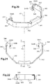
- This flange 340 is more particularly represented on the figures 3 , 4 , 20, 21 and 22 .
- the flange is made of steel.
- It is in the form of a metal strip shaped so as to be inserted into a cylindrical groove 326 of the second ring 320 delimited between the outer 320A and inner 320B walls of the second ring 320.
- the flange 340 extends generally along a semicircle. It presents here more precisely the shape of a half-octagon. Here, it is a semi-base octagonal cylinder and central axis Y3. It thus comprises a central segment 341, two intermediate segments 342 disposed around the central segment 341 as well as two end segments 343. These different segments extend in parallel planes parallel to the central axis Y3.
- the two end segments 343 extend at rest substantially parallel to each other. They further comprise, at their free end, a return 344 folded towards the inside of the flange 340, in the form of a hook.
- the return 344 includes a first portion 344A which extends in a plane substantially perpendicular to the end segment 343, inclined relative to the central axis Y3, and a second portion 344B folded towards the central segment 341 of the flange 340. From this second portion 344B extends, in the direction of the end segment 343 carrying the return 344, a tip 345.
- the inner wall 320B of the second ring 320 furthermore comprises two diametrically opposed slots 327 ( figures 4 , 6 , 7 , 10 and 11 ).
- the cylindrical groove 326 formed between the outer walls 320A and inner 320B of the second ring 320 thus communicates with the central opening of the second ring 320 through these slots 327.
- Each slot 327 is located midway between the guide ribs 324B which extend from the inner face of the inner wall 320B facing the central opening of the second ring 320.
- each slot 327 extends vis-à-vis one of the lateral grooves 172A of the lateral wings 172 of the pole 170.
- the returns 344 pass through the slots 327, so that the second portion 344B of this return 344, provided with the tip 345, extends into outside the cylindrical groove 326, and is housed in the lateral groove 172A of the pole 170 ( figure 4 ).
- the tips 345 are hooked on the internal faces of the reentrant walls 172B of the lateral groove 172A.
- the tips 345 of the steel flange 340 scratch the inner faces of the pole 170 aluminum.
- the flange 340 thus forms a stop for the second ring 320, whose sliding along the pole 170 towards its front end is blocked by the flange 340.
- the second ring 320 is thus locked forwardly sliding and pivoting around of the pole 170.
- the second ring can be fixedly mounted on the pole by any means known to those skilled in the art. It can for example be screwed on the pole.
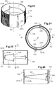
- the locking ring 330 is more particularly represented on the Figures 23 to 26 .
- This ring comprises a cylindrical sleeve 331 of central axis Y4, adapted to surround said first and second rings 310, 320 when the locking ring 330 is mounted on the column 100.
- the central axis Y4 of the sleeve 331 coincides with the longitudinal axis X of the column 100 when the latter is attached to said column 100.
- the inner face 331B of the sleeve 331 oriented towards the central axis Y4 bears in relief and in facing relation, that is to say diametrically opposed, at least two elements of cooperation with said first and second cam surfaces.
- a greater number of cooperation elements distributed regularly along the inner face 331B of the sleeve 331 could be provided, for example three or four cooperation elements.
- the shape of the cam surfaces is then adjusted accordingly, for example three-thirds of a helix revolution or four-quarters of a helix revolution.
- Each cooperation element comprises two opposite bearing surfaces, arranged at a non-zero distance from each other along the central axis Y4 of the sleeve 331, parallel to this central axis Y4 and arranged each in contact with one of said cam surfaces.
- Each cooperation element may optionally comprise two distinct reliefs each carrying one of these bearing surfaces.
- the inner face 331B of the sleeve 331 oriented towards the central axis Y4 bears in relief and vis-à-vis two uprights 336 parallel to each other and parallel to the central axis Y4. They extend over part of the height of the inner face 331B of the sleeve 331. These amounts 336 here constitute said elements of cooperation.
- Each upright 336 has two opposite ends adapted to bear respectively on the first and second cam surfaces 301, 302 of the first and second rings 310, 320 when the locking ring 330 is mounted on the column 100, between said first and second rings 310, 320.
- the opposite ends of the uprights 336 have for this purpose a rounded shape. They constitute said bearing surfaces of the cooperation elements constituted by the amounts.
- the two uprights 336 are connected by a rib 334 which extends on the circumference of the inner face 331B of the sleeve 331.
- This rib has here a T-shape ( figure 25 and 26 ).
- the sleeve 331 also bears here, on its outer face 331A, two raised ribs 333 which are positioned in line with the uprights 336 carried by the inner face 331B of the sleeve 331. These ribs 333 facilitate the manipulation of the locking ring 330 by the installer and constitute visual references of the position of the uprights 336 of the inner face 331B of the sleeve 331.
- the outer face 331A of the sleeve 331 also comprises grooves 332 which extend longitudinally, that is to say according to a direction parallel to the central axis Y4 of the locking ring 330.
- the ridges 332 are located on two diametrically opposed zones of the outer face 331A of the sleeve 331, each covering an angular sector of about 100 ° and they extend over the entire height of the locking ring 330. They improve the grip of hand of the locking ring 330 by the installer (see figure 23 ).
- said first and second rings 310, 320 are here respectively fixed on the frame 110 and associated the pole 170 so that the locations of the first and second rings 310, 320 where the height of the outer wall 310A, 320A is minimum or maximum face each other ( figure 3 ).
- the difference between the first and second cam surfaces 301, 302 thus varies between a minimum distance, at the locations where the outer walls 310A, 320A of the two rings 310, 320 have a maximum height H2, H4, and a maximum gap, places where the outer walls 310A, 320A of the two rings 310, 320 have a minimum height H1, H3.
- each post 336 The rounded surfaces of the opposite ends of each post 336 are in contact with the cam surfaces 301, 302.
- the first and second rings 310, 320 are then, along the longitudinal axis X, as close as possible to one another.
- the second ring 320 is locked between the locking ring 330 and the flange 340, in contact with these two elements.
- the pole 170 is in a low position, in which the length of the pole 170 protruding from the frame is the smallest, and the compression spring 190 is relaxed (see figure 1 ).
- the second ring 320 in abutment against the flange 340 fixed on the perch 170, carries with it the pole 170, which slides in the frame 110 so as to deviate from this frame 110, and move closer to the ceiling or the support wall if it is different from the ceiling.
- the pole 170 is then secured to the second ring 320 when it is moved forward, that is to say towards the support wall.
- the pole 170 and the second ring 320 are fast sliding forward.
- the maximum spacing distance of the pole 170 relative to the frame 110 during the pivoting of the locking ring 330 is equal to the sum of the differences between H2 and H1, on the one hand, and between H3 and H4, d 'somewhere else.
- this spacing distance is 18 millimeters, each difference in height between H2 and H1, on the one hand, and between H3 and H4, on the other hand, being equal to 9 millimeters.
- the pole 170 At the end of the stroke of the locking ring 330, in a second angular position of the locking ring corresponding to the figure 2 , the pole 170 is in a high position, in which the length of the pole protruding from the frame is the largest, and the compression spring 190 is compressed ( figure 2 ).
- the length of the boom 170 projecting from the frame 110 is increased by the spacing distance defined above.
- the angular travel of the locking ring 330 is limited by the abutment of the opposite ends of each upright 336 with the pads 319, 329 facing each other.
- the angular amplitude of pivoting of the locking ring 330 is here limited to 170 °.
- the pivoting stroke of the locking ring may be limited to an angle value of between 80 and 170 °.
- the different elements of the column 100 are positioned relative to each other and the frame 110 is assembled.
- the cover 311 is attached to the front end of the frame 110, the pole 170 is inserted into the frame 110 via the central opening 314 of the first ring 310.
- the ring of 330 and the second ring 320 comprising the flange 340.
- These elements of the bearing device 300 are positioned vertically relative to each other so that, in the first angular position of the locking ring 330, the spring of compression 190 is relaxed.
- the installer pulls the pole 170 until the platform 180 is in contact with the ceiling, then he fixes the second ring 320 on the pole 170 by means of the flange 340.
- the flange 340 is positioned on the pole 170 as a function of the height between the front end of the frame 110 and the support wall of the column 100, so as to block the second ring 320 between the locking ring 330 and the flange 340 in the first angular position.
- the pole 170 is secured to the second ring 320, in particular, integral in pivoting and sliding.
- the installer only has to manually enter the locking ring 330 and rotate it by 170 ° clockwise.
- the installer unlocks the fastener by rotating the locking ring by 170 ° counter-clockwise.
- the spring 190 relaxes and the column 100 can be disassembled.
- the pole 170 is then secured to the second ring 320 sliding backwards, that is to say towards the ground, because of the weight of the pole 170.
- the assembly of the support device 300 can be masked by an unrepresented false ceiling arriving touching the front end of the frame 110.
- the installer may optionally attach the platform 180 to the ceiling, as well as the foot of the column on the floor (not shown).
- the column according to the invention can extend between any two walls.
- the column has a shape parallelepipedic with a base of any quadrilateral shape, for example hexagonal or octagonal and that the frame of the column has more than two cheeks, for example three or four cheeks, defining between them more than two ducts, for example three or four ducts.
Landscapes
- Engineering & Computer Science (AREA)
- Architecture (AREA)
- Civil Engineering (AREA)
- Structural Engineering (AREA)
- Mutual Connection Of Rods And Tubes (AREA)
- Clamps And Clips (AREA)
- Installation Of Indoor Wiring (AREA)
Abstract
L'invention concerne une colonne (100) pour le support d'appareillage électrique, et/ou le cheminement de câbles ou de conducteurs de transport d'énergie, s'étendant selon un axe longitudinal (X) et comportant une ossature (110) allongée délimitant au moins un conduit, et un dispositif de mise en appui (300) de cette ossature entre deux parois, comprenant une perche (170) télescopique partiellement logée dans ladite ossature et dont une partie s'étend dans le prolongement de ladite ossature. Selon l'invention, ledit dispositif de mise en appui comprend une première surface de came (301) solidaire de ladite ossature (110), une deuxième surface de came (302) associée à ladite perche (170), et une bague de verrouillage (330) agencée pour coopérer avec les première et deuxième surfaces de came afin de déplacer la perche par rapport à l'ossature lors de la rotation de ladite bague de verrouillage autour de l'axe longitudinal de la colonne.The invention relates to a column (100) for the support of electrical equipment, and / or the routing of cables or transmission conductors, extending along a longitudinal axis (X) and comprising a framework (110). elongated housing delimiting at least one duct, and a support device (300) for this framework between two walls, comprising a telescopic pole (170) partially housed in said frame and a part of which extends in the extension of said frame. According to the invention, said support device comprises a first cam surface (301) integral with said frame (110), a second cam surface (302) associated with said pole (170), and a locking ring ( 330) arranged to cooperate with the first and second cam surfaces to move the boom relative to the frame upon rotation of said locking ring about the longitudinal axis of the column.
Description
La présente invention concerne une colonne pour le support d'au moins un appareillage électrique et/ou le cheminement de câbles ou de conducteurs de transport d'énergie conforme au préambule de la revendication 1.The present invention relates to a column for supporting at least one electrical equipment and / or the routing of cables or conductors for energy transport according to the preamble of claim 1.
L'invention trouve une application particulièrement avantageuse pour la réalisation d'une colonne verticale à fixer entre le sol et le plafond d'une pièce.The invention finds a particularly advantageous application for the production of a vertical column to be fixed between the floor and the ceiling of a room.
De telles colonnes sont placées dans des pièces de grande surface, telles que des bureaux paysagers, et sont maintenues verticalement entre le plancher et le plafond. Elles peuvent également se présenter sous la forme de potelets dont la hauteur est telle que leur sommet arrive au niveau d'un plateau de bureau.Such columns are placed in large areas, such as landscaped offices, and are held vertically between the floor and the ceiling. They can also be in the form of posts whose height is such that their summit reaches the level of an office tray.
Ces colonnes permettent de supporter des appareillages électriques comme des prises de courant, des interrupteurs, des porte-fusibles, des sectionneurs, des disjoncteurs, ou des appareillages informatiques tels que des prises informatiques, ou encore des appareillages téléphoniques tels que des prises de téléphone.These columns can support electrical equipment such as power outlets, switches, fuse holders, disconnectors, circuit breakers, or computer equipment such as computer jacks, or telephone equipment such as telephone sockets.
Elles permettent également le cheminement des câbles ou des fils conducteurs auxquels lesdits appareillages sont connectés. Ces câbles ou fils conducteurs proviennent du sol ou du plafond et sont reçus à l'intérieur de ces colonnes dans des conduits de cheminement de câbles ou fils conducteurs.They also allow the routing of cables or wires to which said devices are connected. These cables or conductors son come from the ground or the ceiling and are received inside these columns in ducts of cables or wires.
On connaît déjà notamment des documents
Ces solutions sont relativement longues et fastidieuses à mettre en oeuvre en raison du vissage/dévissage nécessaire.These solutions are relatively long and tedious to implement because of the necessary screwing / unscrewing.
On connaît en outre des documents
Ces solutions présentent l'inconvénient d'être techniquement complexes.These solutions have the disadvantage of being technically complex.
Enfin, on connaît du document
Afin de remédier aux différents inconvénients de l'état de la technique, l'invention propose une nouvelle colonne comprenant un dispositif de mise en appui simple à fabriquer et à mettre en oeuvre par l'utilisateur.In order to remedy the various disadvantages of the state of the art, the invention proposes a new column comprising a support device simple to manufacture and implement by the user.
Plus particulièrement, l'invention concerne une colonne conforme à la revendication 1.More particularly, the invention relates to a column according to claim 1.
D'autres caractéristiques non limitatives et avantageuses de la colonne conforme à l'invention, prises individuellement ou selon toutes les combinaisons techniquement possibles, sont énoncées dans les revendications 2 à 10.Other non-limiting and advantageous features of the column according to the invention, taken individually or in any technically possible combination, are set forth in
La description qui va suivre en regard des dessins annexés, donnés à titre d'exemples non limitatifs, fera bien comprendre en quoi consiste l'invention et comment elle peut être réalisée.The following description with reference to the accompanying drawings, given as non-limiting examples, will make it clear what the invention consists of and how it can be achieved.
Sur les dessins annexés :
- la
figure 1 est une vue schématique en perspective de la colonne selon l'invention dans laquelle la bague de verrouillage est dans une première position angulaire de déverrouillage, - la
figure 2 est une vue schématique en perspective de la colonne selon l'invention dans laquelle la bague de verrouillage est dans une deuxième position angulaire de verrouillage, - la
figure 3 est une vue schématique partielle en perspective similaire auxfigures 1 et 2 , dans laquelle les éléments du dispositif de mise en appui sont éclatés, - la
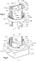
figure 4 est une vue schématique agrandie du détail D1 de lafigure 3 , - la
figure 5 est une vue schématique agrandie du détail D2 de lafigure 3 , - la
figure 6 est une vue schématique en perspective de dessus du deuxième anneau du dispositif de mise en appui de lafigure 5 , - la
figure 7 est une vue schématique en perspective de dessous du deuxième anneau du dispositif de mise en appui de lafigure 5 , - la
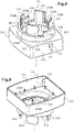
figure 8 est une vue schématique en perspective de dessus du premier anneau du dispositif de mise en appui, - la
figure 9 est une vue schématique en perspective de dessous du premier anneau du dispositif de mise en appui, - la
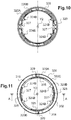
figure 10 est une vue schématique de dessus du deuxième anneau de lafigure 6 , - la
figure 11 est une vue schématique de dessous du deuxième anneau de lafigure 6 , - la
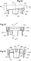
figure 12 est une vue schématique de profil du deuxième anneau de lafigure 6 , - la
figure 13 est une vue schématique en coupe selon le plan A-A de lafigure 11 , - la
figure 14 est une vue schématique en coupe selon le plan B-B de lafigure 13 , - la
figure 15 est une vue schématique de dessous du premier anneau de lafigure 8 , - la
figure 16 est une vue schématique de dessus du premier anneau de lafigure 8 , - la
figure 17 est une vue schématique de profil du premier anneau de lafigure 8 , - la
figure 18 est une vue schématique en coupe selon le plan A'-A' de lafigure 16 , - la
figure 19 est une vue schématique en coupe selon le plan B'-B' de lafigure 18 , - la
figure 20 est une vue schématique en perspective d'un élément de fixation du deuxième anneau du dispositif de mise en appui, - la
figure 21 est une vue schématique de dessus de l'élément de fixation du deuxième anneau de lafigure 20 , - la
figure 22 est une vue schématique en coupe selon le plan C-C de lafigure 21 , - la
figure 23 est une vue schématique en perspective de la bague de verrouillage du dispositif de mise en appui, - la
figure 24 est une vue schématique de dessus de la bague de verrouillage de lafigure 23 , - la
figure 25 est une vue en coupe selon le plan D-D de lafigure 24 , et - la
figure 26 est une vue en coupe selon le plan E-E de lafigure 25 .
- the
figure 1 is a schematic perspective view of the column according to the invention in which the locking ring is in a first unlocking angular position, - the
figure 2 is a schematic perspective view of the column according to the invention in which the locking ring is in a second locking angular position, - the
figure 3 is a partial schematic view in perspective similar toFigures 1 and 2 in which the elements of the support device are exploded, - the
figure 4 is an enlarged schematic view of the detail D1 of thefigure 3 , - the
figure 5 is an enlarged schematic view of detail D2 of thefigure 3 , - the
figure 6 is a schematic perspective view from above of second ring of the support device of thefigure 5 , - the
figure 7 is a schematic perspective view from below of the second ring of the support device of thefigure 5 , - the
figure 8 is a diagrammatic perspective view from above of the first ring of the support device, - the
figure 9 is a schematic perspective view from below of the first ring of the support device, - the
figure 10 is a schematic view from above of the second ring of thefigure 6 , - the
figure 11 is a schematic bottom view of the second ring of thefigure 6 , - the
figure 12 is a schematic profile view of the second ring of thefigure 6 , - the
figure 13 is a schematic sectional view according to the plane AA of thefigure 11 , - the
figure 14 is a schematic sectional view along the plane BB of thefigure 13 , - the
figure 15 is a schematic view from below of the first ring of thefigure 8 , - the
figure 16 is a schematic view from above of the first ring of thefigure 8 , - the
figure 17 is a schematic profile view of the first ring of thefigure 8 , - the
figure 18 is a schematic sectional view along the plane A'-A 'of thefigure 16 , - the
figure 19 is a schematic sectional view along the plane B'-B 'of thefigure 18 , - the
figure 20 is a schematic perspective view of a fixing element of the second ring of the support device, - the
figure 21 is a schematic view from above of the fastening element of the second ring of thefigure 20 , - the
figure 22 is a schematic sectional view along the plane CC of thefigure 21 , - the
figure 23 is a schematic perspective view of the ring of locking of the support device, - the
figure 24 is a schematic view from above of the locking ring of thefigure 23 , - the
figure 25 is a sectional view along the plane DD of thefigure 24 , and - the
figure 26 is a sectional view according to the EE plan of thefigure 25 .
Dans la suite, le côté avant des pièces décrites correspondra à celui orienté vers le plafond et le côté arrière correspondra à celui orienté vers le sol.In the following, the front side of the parts described will correspond to the one facing the ceiling and the back side will correspond to that facing the floor.
On a représenté partiellement, sur les
Bien entendu, cette colonne 100 peut supporter toute sorte d'appareillages électriques, notamment des appareillages alimentés par du courant fort comme des prises de courant et des interrupteurs, mais aussi des appareillages alimentés par du courant faible, comme des appareillages informatiques et téléphoniques.Of course, this
Cette colonne 100 est destinée à être mise en appui entre deux parois. Elle comporte à cet effet un dispositif de mise en appui entre deux parois.This
Il s'agit notamment d'une colonne verticale, destinée à être mise en appui entre le sol et le plafond d'une pièce.This is particularly a vertical column, intended to be placed between the floor and the ceiling of a room.
Elle peut également par exemple être mise en appui entre le sol et une paroi horizontale telle que la plaque horizontale d'un bureau.It can also for example be placed in abutment between the ground and a horizontal wall such as the horizontal plate of a desk.
La colonne 100 comprend une ossature 110 allongée selon un axe longitudinal X. Cette ossature 110 présente ici une forme globalement parallélépipédique, de base sensiblement carrée, avec quatre faces principales opposées parallèles deux à deux.
Elle est réalisée avantageusement en matière métallique telle que de l'aluminium.It is advantageously made of metallic material such as aluminum.
Le dispositif de mise en appui 300 de cette ossature 110 comprend notamment une perche 170 télescopique partiellement logée dans ladite ossature 110 et dont une partie s'étend dans le prolongement de ladite ossature 110.The
Plus précisément, la perche 170 comprend une partie inférieure logée à coulissement dans l'ossature 110 et une partie supérieure qui fait saillie hors de l'ossature 110 à travers une extrémité de l'ossature 110 (voir
Ici, la perche 170 fait saillie à travers l'extrémité avant de l'ossature 110, destinée à être orientée en direction du plafond.Here, the
L'ossature 110 comprend au moins deux joues 120 (
En effet, lesdits moyens de montage peuvent être adaptés à recevoir directement des moyens de montage complémentaires prévus sur le socle de chaque appareillage ou des moyens de montage d'un support destiné au montage de tels appareillages.Indeed, said mounting means may be adapted to directly receive complementary mounting means provided on the base of each apparatus or means for mounting a support for mounting such apparatus.
Ici, l'ossature 110 comprend en outre au moins deux éléments d'entretoise 200 distincts reliant les joues 120 entre elles, les deux éléments d'entretoise 200 étant espacés l'un de l'autre, le long dudit axe longitudinal, d'une distance supérieure ou égale à la hauteur de l'un des éléments d'entretoise 200.Here, the
Les éléments d'entretoise 200 maintiennent les deux joues 120 ensemble, écartées entre elles d'une même distance égale à la largeur de l'élément d'entretoise 200 (
Les éléments d'entretoise 200 sont formées de pièces individuelles distinctes et séparées, disposées à distance les unes des autres, comme mentionné précédemment.The
Ces pièces sont réalisées par moulage d'une matière plastique rigide ou métallique.These parts are made by molding a rigid plastic or metal material.
Les deux joues 120 délimitent, avec lesdits éléments d'entretoise 200, au moins un conduit pour le logement du ou des appareillages électriques ainsi que le logement des câbles ou conducteurs nécessaires à la desserte de chaque appareillage.The two
En pratique, de préférence, chaque conduit est adapté à accueillir une pluralité d'appareillages électrique.In practice, preferably, each duct is adapted to accommodate a plurality of electrical equipment.
Ici, les joues 120 forment deux faces principales opposées de l'ossature 110 et délimitent deux conduits qui s'ouvrent chacune sur l'une des deux autres faces principales opposées de l'ossature 110.Here, the
Les joues 120 forment ainsi les ailes latérales délimitant chaque conduit, tandis que les éléments d'entretoise 200 forment un fond de ces conduits.The
Les deux conduits sont ainsi ici disposés dos à dos. Ils s'ouvrent chacun par une ouverture longitudinale 140 s'étendant selon l'axe longitudinal X de la colonne 100. Chaque ouverture longitudinale 140 est délimitée par deux bords libres 121 en vis-à-vis des deux joues 120 (voir
Chacune des ouvertures longitudinales 140 desdits conduits est destinée à être fermée par des tronçons de couvercle (ici, non représentés) qui s'étendent entre les façades des appareillages électriques rapportés dans les conduits.Each of the
Plus précisément, ici, lesdits éléments d'entretoise 200 forment un fond discontinu pour les conduits.More specifically, here, said
Ainsi, sur une grande partie de leur longueur, les deux conduits communiquent entre eux.Thus, over a large part of their length, the two ducts communicate with each other.
L'absence de fond sur une grande partie de la longueur du conduit, le long de l'axe longitudinal X de la colonne 100, permet de libérer de l'espace à l'intérieur de la colonne 100, pour un même volume externe global de la colonne.The absence of a bottom over a large part of the length of the duct, along the longitudinal axis X of the
Ainsi, la colonne 100 présente une plus grande capacité d'accueil des appareillages électriques et des câbles électriques que les colonnes classiques déjà connues.Thus, the
Comme le montrent les
L'un des deux éléments d'entretoise 200 est disposé à proximité d'une première extrémité longitudinale de la colonne 100, par exemple son extrémité avant destinée à être disposée à proximité du plafond, tandis que l'autre élément d'entretoise 200 est disposé à proximité de l'autre extrémité longitudinale de la colonne 100, par exemple son extrémité arrière destinée à être disposé à proximité du sol.One of the two
En variante, on peut prévoir par exemple un troisième élément d'entretoise disposé à proximité du milieu de la colonne.Alternatively, there may be provided for example a third spacer element disposed near the middle of the column.
On peut également prévoir une pluralité d'éléments d'entretoise. Le nombre d'éléments d'entretoise maximal dépend de la hauteur des éléments d'entretoise et de la hauteur totale de la colonne.It is also possible to provide a plurality of spacer elements. The maximum number of spacer members depends on the height of the spacer members and the total height of the column.
Les éléments d'entretoise sont de préférence répartis régulièrement le long de l'ossature 110, c'est-à-dire espacés entre eux d'une même distance prédéterminée.The spacer elements are preferably distributed regularly along the
Préférentiellement, l'ossature 110 mesure entre 50 centimètres et 4 mètres de hauteur le long de l'axe longitudinal X, par exemple environ 2,5 mètres. Chaque élément d'entretoise 200 mesure quelques centimètres de hauteur selon l'axe longitudinal X.Preferably, the
En particulier, chaque élément d'entretoise 200 présente de préférence une hauteur H mesurée le long de l'axe longitudinal de la colonne comprise entre 1 et 20 centimètres, de préférence comprise entre 2 et 10 centimètres, par exemple égale à 4 centimètres (
Chaque joue 120 comporte un flanc 121A globalement rectangulaire, allongé selon l'axe longitudinal X de la colonne 100.Each
Chaque flanc 121A présente ici un profil légèrement arqué pour une question purement esthétique. Chaque joue 120 comporte, le long des deux bords longitudinaux de son flanc 121A, deux retours 121B parallèles qui s'étendent globalement perpendiculairement au flanc 121A (
Lorsque les joues 120 sont reliées par les éléments d'entretoise 200 (voir
Un retour 121B d'une des joues 120 s'étend en direction d'un retour 121B de l'autre joue 120.A
Les deux bords libres 121 des deux retours 121B en vis-à-vis délimitent les bords de l'ouverture longitudinale 140 d'un conduit formé par l'ossature 110.The two
A proximité de chaque retour 121B, la face interne du flanc 121A porte une structure d'accrochage 122 profilée le long de l'axe longitudinal X de la colonne.Near each
Cette structure d'accrochage 122 sert au montage des tronçons de couvercle (non représentés) pour fermer l'ouverture longitudinale 140 de chaque conduit de la colonne 100. Elle sert également au montage des divers appareillages électriques (non représentés) dans les conduits de la colonne 100.This
Généralement, les appareillages électriques sont montés sur des supports encliquetés sur cette structure d'accrochage 122, de telle sorte que l'avant desdits appareillages apparaisse au travers de l'ouverture longitudinale 140 du conduit accueillant les appareillages. Ces appareillages ferment alors localement cette ouverture longitudinale 140.Generally, the electrical equipment is mounted on supports latched on this
En variante, on peut également prévoir que le socle de chaque mécanisme d'appareillage électrique s'accroche directement à la structure d'accrochage 122.Alternatively, it is also possible that the base of each electrical equipment mechanism clings directly to the
Les tronçons de couvercle, ici, non représentés, présentent une forme allongée et sont destinés à fermer les ouvertures longitudinales 140 des conduits aux endroits où aucun appareillage électrique n'est installé. Ainsi, les quatre faces de la colonne 100 sont fermées et la sécurité électrique est assurée.The lid sections, here not shown, have an elongated shape and are intended to close the
Ces tronçons de couvercle comprennent chacun un panneau de fermeture sensiblement rectangulaire muni de moyens d'encliquetage sur la structure d'accrochage 122.These lid sections each comprise a substantially rectangular closure panel provided with latching means on the
Chaque joue 120 comprend également, sur sa face interne tournée vers l'intérieur de la colonne 100, des moyens de montage de l'élément d'entretoise 200, adaptés à coopérer à retenue avec des moyens de montage complémentaires de chaque élément d'entretoise 200.Each
Ici, il s'agit de moyens de montage par encliquetage.Here, it is snap mounting means.
Les moyens de montage complémentaires de chaque élément d'entretoise 200 sont situés sur deux parois de montage opposées de cet élément d'entretoise.The complementary mounting means of each
Une partie centrale de l'élément d'entretoise 200 forme avec les parois de montage un manchon qui s'étend, dans l'ossature 110, selon l'axe longitudinal X (
La partie centrale comporte ici à cet effet deux parois s'étendant en vis-à-vis, parallèlement l'une à l'autre entre les deux parois de montage.The central portion here comprises for this purpose two walls extending vis-a-vis, parallel to each other between the two mounting walls.
Ce manchon accueille la perche 170 télescopique (
La perche 170 est plus précisément introduite dans le manchon formé par la partie centrale de l'élément d'entretoise 200 situé à proximité de l'extrémité avant de l'ossature 100, c'est-à-dire à proximité de l'extrémité de l'ossature la plus proche du plafond.The
La section transverse du manchon délimité par la partie centrale de l'élément d'entretoise 200 présente à cette effet une forme semblable à celle de la section transverse de la perche 170.The transverse section of the sleeve delimited by the central part of the
Cette section transverse présente ici une forme en H.This transverse section here has a shape in H.
La perche 170, telle que représentée sur les
Une rainure latérale 172A est ménagée dans la face externe de chaque aile latérale 172 de la perche 170. Cette rainure 172A s'étend longitudinalement le long de la perche 170 et s'ouvre vers l'extérieur de la perche 170.A
Chaque rainure 172A de la perche 170 s'étend au milieu de chaque aile latérale 172. Chaque rainure 172A présente par ailleurs une section en T qui s'élargit vers son fond, de telle sorte que l'ouverture longitudinale délimitée par le débouché de la rainure 172A, sur la face externe de l'aile latérale 172, est bordée de deux éléments de paroi rentrants 172B (
Les dimensions transverses internes du manchon formé par la partie centrale 220 de l'élément d'entretoise 200 sont sensiblement égales, à un jeu près, aux dimensions externes de cette perche 170, de sorte à autoriser le coulissement de la perche 170 dans le manchon.The internal transverse dimensions of the sleeve formed by the central portion 220 of the
A son extrémité avant, située à l'extérieur de l'ossature 110, la perche 170 est raccordée à une plate-forme 180 pourvue de moyens permettant sa fixation à une paroi horizontale située au-dessus du sol et avantageusement au plafond (voir
La plate-forme 180 est une plaque métallique rigide. Plus précisément, comme le montre la
Les pattes de fixation 182 comprennent chacune un orifice 181 pour le passage de moyens de fixation sur le plafond, tels que des vis. Elles sont appliquées contre le plafond.The fixing lugs 182 each comprise an
Cette plate-forme 180 comprend également une partie de coopération avec la perche 170, comprenant une languette 183 qui est pliée à 90° par rapport au tronc central rigide de la partie de fixation, de manière à s'étendre parallèlement à l'axe longitudinal X de la colonne 100 (
Cette languette 183 est insérée dans la lame creuse longitudinale 171 de la perche 170 (
Elle comporte, à proximité de son extrémité libre, deux zones 184 en relief sur l'une des faces de la languette 183, qui s'étendent perpendiculairement à l'axe longitudinal de la languette 183 et donc à l'axe longitudinal X de la colonne 100 lorsque la languette 183 est reçue dans la perche 170 (
Ces zones 184 en relief sont adaptées à coopérer avec la perche 170 pour guider la languette 183 dans la lame creuse longitudinale 171.These
Le dispositif de mise en appui de la colonne comprend de préférence une partie de hauteur ajustable le long de l'axe longitudinal de la colonne.The support device of the column preferably comprises an adjustable height portion along the longitudinal axis of the column.
Plus précisément, la colonne 100 comprend par exemple une partie comprimable, adaptée à être comprimée de manière réversible, qui est interposée entre l'extrémité avant de la perche et le plafond. Cette partie comprimable permet la mise en appui facile de la colonne entre les deux parois choisies, et une adaptation rapide de la hauteur de la colonne à la distance séparant ces deux parois.Specifically, the
Cette partie comprimable peut comprendre tout moyen connu de l'Homme du métier. Il peut notamment s'agir d'un ressort de compression ou d'un autre type de ressort, par exemple un ressort à lames, d'une ou plusieurs rondelles élastiques ou une ou plusieurs rondelles ondulées, par exemple du type rondelle élastique Ondufil® à spires inversées. Il peut également s'agir d'un anneau en caoutchouc du type Silentbloc®, ou d'un élément comportant un coussin d'air, notamment un vérin à air.This compressible part may include any means known to those skilled in the art. It may especially be a compression spring or another type of spring, for example a leaf spring, one or more spring washers or one or more corrugated washers, for example of the Ondufil® spring washer type inverted turns. It may also be a rubber ring of the Silentbloc® type, or an element comprising an air cushion, in particular an air cylinder.
En variante, il est possible de prévoir des moyens de fixation de la languette à différentes hauteurs dans la lame creuse longitudinale de la perche, par exemple par vissage, pour permettre la mise en appui de la colonne entre les deux parois choisie, et l'adaptation de la hauteur de la colonne à la distance séparant ces deux parois.Alternatively, it is possible to provide means for fixing the tongue at different heights in the longitudinal hollow blade of the pole, for example by screwing, to allow the support of the column between the two walls chosen, and the adaptation of the height of the column to the distance separating these two walls.
Ici, comme le montrent les
Plus précisément, ici, le ressort de compression 190 est interposé entre la partie de fixation de la plate-forme 180 et l'extrémité avant de la perche 170. Il est à cet effet enfilé autour de la partie de la languette 183 de la plate-forme 180 qui fait saillie hors de la perche 170.More specifically, here, the
De manière remarquable, le dispositif de mise en appui de la colonne 100, comprend une première surface de came 301 solidaire de ladite ossature 110, une deuxième surface de came 302 associée à ladite perche 170, et une bague de verrouillage 330 agencée pour coopérer avec les première et deuxième surfaces de came 301, 302 afin de déplacer la perche 170 par rapport à l'ossature 110 lors de la rotation de ladite bague de verrouillage 330 autour de l'axe longitudinal X de la colonne 100 (voir
Comme expliqué par la suite, cet agencement permet une simplification de fabrication et de mise en oeuvre du dispositif de mise en appui en évitant la coopération de surfaces filetées et en supprimant des étapes de vissage/dévissage fastidieuses.As explained later, this arrangement allows simplification of manufacture and implementation of the support device by avoiding the cooperation of threaded surfaces and eliminating tedious screwing / unscrewing steps.
Plus précisément, ici, comme le montre la
Le couvercle 311 est représenté plus particulièrement sur les
Le couvercle 311 comporte une plaque avant 312 dont la forme est similaire à celle de la section de l'ossature 110, c'est-à-dire sensiblement carrée, entourée à l'arrière par une paroi latérale tombante 313 qui vient s'appliquer autour de la face externe de l'extrémité avant de l'ossature 110.The
La plaque avant 312 du couvercle 311 comporte une ouverture centrale 314 circulaire autorisant le passage de la perche 170 (
Cette ouverture centrale 314 d'axe central Y1 est bordée à l'avant par le premier anneau 310 qui, globalement, s'élève sensiblement perpendiculairement à la plaque avant 312 et présente une tranche libre d'extrémité formant la surface de came 301.This
Comme le montre les
Les deux parois externe 310A et interne 310B présentent une hauteur, mesurée le long de l'axe central Y1, variable et sont reliées par une paroi intermédiaire 310C qui forme la tranche libre d'extrémité du premier anneau 310 dont la face externe forme la première surface de came 301. Cette première surface de came présente donc une forme annulaire.The two
Lorsque le couvercle 311 est rapporté à l'extrémité avant de l'ossature 110, l'axe central Y1 de son ouverture central 314 vient en coïncidence avec l'axe longitudinal X de la colonne 100. En outre, la première surface de came 301 est alors tournée vers l'avant.When the
Cette première surface de came 301 forme deux demi-tours d'une première hélice s'enroulant autour dudit axe central Y1. Elle présente ainsi globalement une forme hélicoïdale sur au moins une partie de sa circonférence. La première surface de came s'étend ainsi autour de l'axe central Y1 et sur une hauteur non nulle le long de cet axe central Y1.This
En d'autres termes, comme le montre mieux la
A chaque extrémité la plus haute, là où la première surface de came 301 s'élève à la deuxième hauteur H2, celle-ci porte un plot 319 (
A partir de la paroi interne 310B du premier anneau 310, s'étendent des pions 314A de centrage et de guidage de la perche 170 (
Plus précisément, il s'agit de deux pions 314A diamétralement opposés qui font saillie vers l'axe central Y1, dans un plan perpendiculaire à cet axe central Y1.More precisely, it consists of two diametrically
Chaque pion 314A est adapté à coopérer avec les rainures latérales 172A ménagées dans chaque aile latérale 172 de la perche 170 (
Plus précisément, comme le montre la
La face interne de la paroi interne 310B, tournée vers l'ouverture centrale 314 du premier anneau 310 forme un épaulement 318 (
Dans le prolongement de la paroi interne 310B du premier anneau 310, à partir de cet épaulement 318, s'étendent des pattes 315, vers l'avant lorsque le couvercle 311 est rapporté à l'extrémité avant de l'ossature 110.In the extension of the
Elles sont au nombre de quatre, réparties régulièrement autour de l'axe central Y1 de manière à entourer deux à deux les ailes latérales 172 de la perche 170 lorsque celle-ci est introduite dans l'ossature 110.They are four in number, regularly distributed about the central axis Y1 so as to surround in pairs the
Chaque patte 315 forme une portion de paroi cylindrique qui s'étend dans le prolongement de la paroi interne 310B du premier anneau 310. Chaque patte 315 comprend un bord longitudinal muni d'une nervure longitudinale 314B qui s'étend en saillie vers l'intérieur du premier anneau 310, parallèlement au pion 314A (voir
La présence de ces nervures 314B, ainsi que la forme globalement carrée du couvercle 311 auquel est attaché le premier anneau 310 assurent que celui-ci ne pivote ni autour de la perche 170, ni autour de l'ossature 110 lorsque le couvercle 311 est rapporté à l'extrémité avant de l'ossature 110.The presence of these
Le premier anneau 310 est fixé via le couvercle 311 à l'extrémité de l'ossature 110 et est solidaire de celle-ci : il ne peut ni pivoter, ni coulisser par rapport à cette ossature 110. Il est donc bloqué en pivotement et en coulissement sur l'ossature 110.The
Ladite deuxième surface de came 302 appartient à un deuxième anneau 320 monté sur ladite perche 170.Said
Le deuxième anneau 320 est représenté plus particulièrement sur les
Ce deuxième anneau 320 est réalisé en pratique par une double paroi cylindrique comprenant une paroi externe 320A et une paroi interne 320B concentriques autour d'un axe central Y2 de ce deuxième anneau 320 (
Cette deuxième surface de came présente donc une forme annulaire.This second cam surface therefore has an annular shape.
La paroi externe 320A est délimitée entre un premier bord circulaire arrière formant la base du deuxième anneau 320 et s'étendant dans un plan perpendiculaire à l'axe central Y2, et la paroi intermédiaire 320C qui porte la deuxième surface de came 302.The
Lorsque le deuxième anneau 320 est monté sur la perche 170 qui est reçue dans l'ossature 110, son axe central Y2 vient en coïncidence avec l'axe longitudinal X de la colonne 100.When the
En outre, la deuxième surface de came 302 est alors tournée vers l'arrière. Elle s'étend en vis-à-vis de la première surface de came 301.In addition, the
Cette deuxième surface de came 302 forme deux demi-tours d'une deuxième hélice s'enroulant autour dudit axe central Y2 (
Elle présente ainsi globalement une forme hélicoïdale sur au moins une partie de sa circonférence. La deuxième surface de came s'étend ainsi autour de l'axe central Y2 et sur une hauteur non nulle le long de cet axe central Y2.It thus has a generally helical shape on at least a portion of its circumference. The second cam surface thus extends around the central axis Y2 and on a non-zero height along this central axis Y2.
Lesdites parois internes 320B et externe 320A présentent à cet effet une hauteur variable, mesurée le long de l'axe central Y2.For said purpose, said
En d'autres termes, comme le montrent mieux les
A chaque extrémité la plus haute, là où la deuxième surface de came 302 s'élève à la quatrième hauteur H4, celle-ci porte un plot 329 (
Dans le prolongement de la paroi interne 320B du deuxième anneau 320 s'étendent des pattes 325, vers l'arrière lorsque le deuxième anneau 320 est fixé sur la perche 170.In the extension of the
Elles sont au nombre de quatre et sont réparties régulièrement autour de l'axe central Y2 du deuxième anneau 320, de manière à être insérées entre les pattes 315 s'étendant vers l'avant du premier anneau 310.They are four in number and are regularly distributed around the central axis Y2 of the
Ces pattes 325 forment une portion de paroi cylindrique qui s'étend dans le prolongement de la paroi interne 320B du deuxième anneau 320.These
Il est également prévu, en saillie de la face interne de la paroi interne 320B du deuxième anneau 320, des nervures de guidage 324B qui s'étendent en saillie vers l'intérieur du deuxième anneau 320, en longueur parallèlement à l'axe central Y2 et en hauteur parallèlement à un diamètre du deuxième anneau 320. Ces nervures 324B sont disposées de manière à encadrer l'aile latérale 172 de la perche 170 lorsque celle-ci passe à travers le deuxième anneau 320, de manière similaire aux nervures 314B du premier anneau 310 (
Elles participent au guidage du coulissement de la perche 170. En outre, elles interdisent tout pivotement du deuxième anneau 320 autour de la perche 170. Le deuxième anneau 320 est bloqué en pivotement autour de la perche 170.They participate in guiding the sliding of the
Lorsque les premier et deuxième anneaux 310, 320 sont respectivement en place sur l'ossature 110 et la perche 170, ils sont agencés de telle sorte que les première et deuxième marches des première et deuxième surfaces de came 301, 302 se font face.When the first and
En conséquence, les plots 319, 329 prévus en saillie de chaque surface de came 301, 302, se font face aux endroits où la première et la deuxième surfaces de came 301, 302 s'élèvent à la deuxième et à la quatrième hauteurs H2, H4.Consequently, the
En outre, lesdites première et deuxième surfaces de came 301, 302 s'enroulent selon des sens opposés, à partir d'une même position angulaire autour de l'axe longitudinal X de la colonne 100.In addition, said first and second cam surfaces 301, 302 are wound in opposite directions from the same angular position around the longitudinal axis X of the
Ici, les hélices des première et deuxième surfaces de came 301, 302 sont identiques au sens de l'enroulement près.Here, the propellers of the first and second cam surfaces 301, 302 are identical in the direction of the winding close.
En conséquence, les différences entre les hauteurs H2 et H1, d'une part, et H3 et H4, d'autre part, sont égales.As a result, the differences between the heights H2 and H1, on the one hand, and H3 and H4, on the other hand, are equal.
Ici, les parois externes 310A, 320A sont identiques. En conséquence, les première et troisième hauteurs H1 et H3 sont égales, et les deuxième et quatrième hauteurs H2 et H4 sont égales.Here, the
Les première et deuxième surfaces de came 301, 302 sont ici les images miroir l'une de l'autre.The first and second cam surfaces 301, 302 here are the mirror images of each other.
Les dimensions respectives des pattes 315, 325 des premier et deuxième anneaux 310, 320 sont telles qu'elles s'imbriquent les unes dans les autres lorsque les deux anneaux 310, 320 sont montés sur l'ossature 110 et la perche 170. Elles sont jointives et forment ensemble une paroi cylindrique.The respective dimensions of the
Les hauteurs respectives des pattes 315 du premier anneau 310 et des pattes 325 du deuxième anneau 320, le long des axes centraux Y1, Y2 des deux anneaux 310, 320, sont telles que ces pattes restent au moins partiellement imbriquées les unes dans les autres lors de la rotation de la bague de verrouillage 330.The respective heights of the
Les bords longitudinaux des pattes 315, 325 des premier et deuxième anneaux 310, 320 s'appuient les uns contre les autres pour empêcher toute rotation du deuxième anneau 320 par rapport au premier anneau 310.The longitudinal edges of the
En outre, la coopération de ces pattes 315, 325 lors du coulissement de la perche 170, actionné, comme expliqué plus loin, par la rotation de la bague de verrouillage 330, confère de la rigidité à l'ensemble du dispositif de mise en appui 300.In addition, the cooperation of these
Le deuxième anneau 320 comprend en outre des moyens de coopération avec la perche 170, sous la forme d'une bride 340. Cette bride 340 est plus particulièrement représentée sur les
Elle est réalisée dans une matière présentant une dureté supérieure à celle de la matière de la perche. Ici, par exemple, la bride est réalisée en acier.It is made of a material having a hardness superior to that of the material of the pole. Here, for example, the flange is made of steel.
Elle se présente sous la forme d'une bande métallique conformée de manière à pouvoir être insérée dans une gorge cylindrique 326 du deuxième anneau 320, délimitée entre les parois externe 320A et interne 320B de ce deuxième anneau 320.It is in the form of a metal strip shaped so as to be inserted into a
La bride 340 s'étend globalement le long d'un demi-cercle. Elle présente ici plus précisément la forme d'un demi-octogone. Ici, il s'agit d'un demi-cylindre de base octogonal et d'axe central Y3. Elle comprend ainsi un segment central 341, deux segments intermédiaires 342 disposés autour du segment central 341 ainsi que deux segments d'extrémité 343. Ces différents segments s'étendent selon des plans moyens parallèles à l'axe central Y3.The
Les deux segments d'extrémité 343 s'étendent au repos sensiblement parallèlement l'un à l'autre. Ils comportent en outre, à leur extrémité libre, un retour 344 replié vers l'intérieur de la bride 340, en forme de crochet.The two
Plus précisément, le retour 344 comporte une première partie 344A qui s'étend dans un plan sensiblement perpendiculaire au segment d'extrémité 343, incliné par rapport à l'axe central Y3, et une deuxième partie 344B repliée en direction du segment central 341 de la bride 340. A partir de cette deuxième partie 344B s'étend, en direction du segment d'extrémité 343 portant le retour 344, une pointe 345.More specifically, the
La paroi interne 320B du deuxième anneau 320 comporte en outre ici deux fentes 327 diamétralement opposées (
Chaque fente 327 est située à mi-chemin entre les nervures de guidage 324B qui s'étendent à partir de la face interne de la paroi interne 320B tournée vers l'ouverture centrale du deuxième anneau 320.Each
Ainsi, lorsque le deuxième anneau 320 est en place autour de la perche 170, chaque fente 327 s'étend en vis-à-vis de l'une des rainures latérales 172A des ailes latérales 172 de la perche 170.Thus, when the
Lorsque la bride 340 est mise en place dans la gorge cylindrique 326 du deuxième anneau 320, les retours 344 traversent les fentes 327, de manière à ce que la deuxième partie 344B de ce retour 344, muni de la pointe 345, s'étend en dehors de la gorge cylindrique 326, et se loge dans la rainure latérale 172A de la perche 170 (
La bride 340 forme ainsi une butée pour le deuxième anneau 320, dont le coulissement le long de la perche 170 vers son extrémité avant est bloqué par la bride 340. Le deuxième anneau 320 est ainsi bloqué en coulissement vers l'avant et en pivotement autour de la perche 170.The
En outre, lorsque le deuxième anneau 320 est en place sur la perche 170, celui-ci est également bloqué en coulissement vers l'arrière par la bague de verrouillage 330.In addition, when the
En variante, le deuxième anneau peut être monté fixement sur la perche par tout moyen connu de l'Homme du métier. Il peut par exemple être vissé sur la perche.Alternatively, the second ring can be fixedly mounted on the pole by any means known to those skilled in the art. It can for example be screwed on the pole.
La bague de verrouillage 330 est plus particulièrement représentée sur les
Cette bague comprend un manchon 331 cylindrique d'axe central Y4, adapté à entourer lesdits premier et deuxième anneaux 310, 320 lorsque la bague de verrouillage 330 est montée sur la colonne 100.This ring comprises a
L'axe central Y4 du manchon 331 est confondu avec l'axe longitudinal X de la colonne 100 lorsque celui-ci est rapporté sur ladite colonne 100.The central axis Y4 of the
De manière générale, la face interne 331B du manchon 331 orientée vers l'axe central Y4 porte en relief et en vis-à-vis, c'est-à-dire diamétralement opposés, au moins deux éléments de coopération avec lesdites première et deuxième surfaces de came.In general, the
En variante, on pourrait prévoir un plus grand nombre d'éléments de coopération répartis régulièrement le long de la face interne 331B du manchon 331, par exemple trois ou quatre éléments de coopération. La forme des surfaces de came est alors ajustée en conséquence, par exemple trois tiers de tour d'hélice ou quatre quarts de tour d'hélice.As a variant, a greater number of cooperation elements distributed regularly along the
Chaque élément de coopération comporte deux surfaces d'appui opposées, disposées à une distance non nulle l'une de l'autre le long de l'axe central Y4 du manchon 331, parallèlement à cet axe central Y4 et disposée chacune en contact avec l'une desdites surfaces de came. Chaque élément de coopération peut éventuellement comporter deux reliefs distincts portant chacun l'une de ces surfaces d'appui.Each cooperation element comprises two opposite bearing surfaces, arranged at a non-zero distance from each other along the central axis Y4 of the
Ici, la face interne 331B du manchon 331 orientée vers l'axe central Y4 porte en relief et en vis-à-vis deux montants 336 parallèles entre eux et parallèles à l'axe central Y4. Ils s'étendent sur une partie de la hauteur de la face interne 331B du manchon 331. Ces montants 336 constituent ici lesdits éléments de coopération.Here, the
Chaque montant 336 comporte deux extrémités opposées adaptées à s'appuyer respectivement sur les première et deuxième surfaces de came 301, 302 des premier et deuxième anneaux 310, 320 lorsque la bague de verrouillage 330 est montée sur la colonne 100, entre lesdits premier et deuxième anneaux 310, 320. Les extrémités opposées des montants 336 présentent à cet effet une forme arrondie. Elles constituent lesdites surfaces d'appui des éléments de coopération constitués par les montants.Each
Ici, les deux montants 336 sont reliés par une nervure 334 qui s'étend sur la circonférence de la face interne 331B du manchon 331.Here, the two
Cette nervure présente ici une forme en T (
Le manchon 331 porte en outre ici, sur sa face externe 331A, deux nervures 333 en relief qui sont positionnées au droit des montants 336 portés par la face interne 331B du manchon 331. Ces nervures 333 facilitent la manipulation de la bague de verrouillage 330 par l'installateur et constituent des repères visuels de la position des montants 336 de la face interne 331B du manchon 331. La face externe 331A du manchon 331 comprend également des stries 332 qui s'étendent longitudinalement, c'est-à-dire selon une direction parallèle à l'axe central Y4 de la bague de verrouillage 330.The
Les stries 332 se trouvent sur deux zones diamétralement opposées de la face externe 331A du manchon 331, couvrant chacune un secteur angulaire d'environ 100° et elles s'étendent sur toute la hauteur de la bague de verrouillage 330. Elles améliorent la prise en main de la bague de verrouillage 330 par l'installateur (voir
Comme le montre la
L'écart entre les première et deuxième surfaces de came 301, 302 varie donc entre un écart minimal, aux endroits où les parois externes 310A, 320A des deux anneaux 310, 320 présentent une hauteur maximale H2, H4, et un écart maximal, aux endroits où les parois externes 310A, 320A des deux anneaux 310, 320 présentent une hauteur minimale H1, H3.The difference between the first and second cam surfaces 301, 302 thus varies between a minimum distance, at the locations where the
Dans une première position angulaire de la bague de verrouillage 330 correspondant à la
Les surfaces arrondies des extrémités opposées de chaque montant 336 sont en contact avec les surfaces de came 301, 302.The rounded surfaces of the opposite ends of each
Les plots 319, 329 s'étendant en saillie des surfaces de came 301, 302 viennent alors par paire en butée l'un contre l'autre et l'extrémité libre des pattes arrière 325 du deuxième anneau 320 prend appui sur l'épaulement 318 de la paroi interne 310B du premier anneau 310.The
Les premier et deuxième anneaux 310, 320 sont alors, selon l'axe longitudinal X, au plus près possible l'un de l'autre.The first and
Le deuxième anneau 320 est bloqué entre la bague de verrouillage 330 et la bride 340, au contact de ces deux éléments.The
Dans cette première position angulaire, la bride 340 est plaquée dans la gorge 326 du deuxième anneau 320 sous l'effet du poids de la perche 170.In this first angular position, the
La perche 170 est dans une position basse, dans laquelle la longueur de la perche 170 faisant saillie hors de l'ossature est la plus petite, et le ressort de compression 190 est détendu (voir
Lorsque la bague de verrouillage 330 est pivotée dans le sens horaire à partir de cette première position, les formes arrondies des extrémités opposées des montants 336 glissent sur les surfaces de came 301, 302. Comme l'écart entre les surfaces de came 301, 302 se réduit au fur et à mesure de la rotation de la bague de verrouillage 330, le deuxième anneau 320 est repoussé vers le plafond (ou la paroi d'appui si celle-ci est différente du plafond) pour permettre le passage des montants 336 entre les deux surfaces de came 301, 302.When the
Le deuxième anneau 320, en butée contre la bride 340 fixée sur la perche 170, entraîne avec lui la perche 170, qui coulisse dans l'ossature 110 de manière à s'écarter de cette ossature 110, et se rapprocher du plafond ou de la paroi d'appui si celle-ci est différente du plafond.The
La perche 170 est alors solidaire du deuxième anneau 320 lorsque celui-ci est déplacé vers l'avant, c'est-à-dire vers la paroi d'appui. La perche 170 et le deuxième anneau 320 sont solidaires en coulissement vers l'avant.The
La distance maximale d'écartement de la perche 170 par rapport à l'ossature 110 lors du pivotement de la bague de verrouillage 330 est égale à la somme des différences entre H2 et H1, d'une part, et entre H3 et H4, d'autre part.The maximum spacing distance of the
Ici, cette distance d'écartement est de 18 millimètres, chaque différence de hauteur entre H2 et H1, d'une part, et entre H3 et H4, d'autre part, étant égale à 9 millimètres.Here, this spacing distance is 18 millimeters, each difference in height between H2 and H1, on the one hand, and between H3 and H4, on the other hand, being equal to 9 millimeters.
A la fin de la course de la bague de verrouillage 330, dans une deuxième position angulaire de la bague de verrouillage correspondant à la
La course angulaire de la bague de verrouillage 330 est limitée par la butée des extrémités opposées de chaque montant 336 avec les plots 319, 329 se faisant face. L'amplitude angulaire de pivotement de la bague de verrouillage 330 est ainsi ici limitée à 170°.The angular travel of the
En variante, la course en pivotement de la bague de verrouillage peut être limitée à une valeur d'angle comprise entre 80 et 170°.Alternatively, the pivoting stroke of the locking ring may be limited to an angle value of between 80 and 170 °.
Dans la deuxième position angulaire de la bague de verrouillage 330, la mise en appui de la colonne 100 est assurée par la pression exercée par le ressort de compression 190 vers le sol sur l'ossature 110, par l'intermédiaire de la perche 170.In the second angular position of the
Ainsi, les différents éléments de la colonne 100 sont positionnés les uns par rapport aux et l'ossature 110 est assemblée.Thus, the different elements of the
Le couvercle 311 est rapporté sur l'extrémité avant de l'ossature 110, la perche 170 est insérée dans l'ossature 110, via l'ouverture centrale 314 du premier anneau 310.The
Sur la perche 170 sont positionnés successivement la bague de verrouillage 330 et le deuxième anneau 320 comportant la bride 340. Ces éléments du dispositif de mise en appui 300 sont positionnés verticalement les uns par rapport aux autres de telle sorte que, dans la première position angulaire de la bague de verrouillage 330, le ressort de compression 190 est détendu. Après avoir positionné la colonne à l'endroit prévu, l'installateur tire la perche 170 jusqu'à ce que la plate-forme 180 soit en contact avec le plafond, puis il fixe le deuxième anneau 320 sur la perche 170 au moyen de la bride 340.On the
La bride 340 est positionnée sur la perche 170 en fonction de la hauteur entre l'extrémité avant de l'ossature 110 et la paroi d'appui de la colonne 100, de manière à bloquer le deuxième anneau 320 entre la bague de verrouillage 330 et la bride 340 dans la première position angulaire.The
En pratique, la perche 170 est solidaire du deuxième anneau 320, en particulier, solidaire en pivotement et en coulissement.In practice, the
Ensuite, l'installateur n'a plus qu'à saisir manuellement la bague de verrouillage 330 et la faire tourner de 170° dans le sens horaire.Then, the installer only has to manually enter the
Ce faisant, il écarte la perche 170 de l'ossature 110 de la distance d'écartement prédéterminée et comprime le ressort de compression 190.In doing so, it separates the
Il verrouille ainsi la fixation de la colonne 100 par la pression appliquée vers le sol par le ressort de compression 190 sur la perche 170 et donc l'ossature 110.It thus locks the fixing of the
Pour démonter la colonne 100, l'installateur déverrouille sa fixation en faisant tourner la bague de verrouillage de 170° dans le sens anti-horaire. Le ressort 190 se détend et la colonne 100 peut être démontée.To dismantle the
La perche 170 est alors solidaire du deuxième anneau 320 en coulissement vers l'arrière, c'est-à-dire vers le sol, en raison du poids de la perche 170.The
L'ensemble du dispositif de mise en appui 300 peut être masqué par un faux plafond non représenté arrivant à effleurement de l'extrémité avant de l'ossature 110.The assembly of the
L'installateur peut éventuellement fixer la plate-forme 180 au plafond, ainsi que le pied de la colonne au sol (non représenté).The installer may optionally attach the
En variante, la colonne selon l'invention peut s'étendre entre deux parois quelconques.Alternatively, the column according to the invention can extend between any two walls.
En variante, on peut prévoir que la colonne présente une forme parallélépipédique avec une base de forme quadrilatère quelconque, par exemple hexagonale ou octogonale et que l'ossature de la colonne comporte plus de deux joues, par exemple trois ou quatre joues, délimitant entre elles plus de deux conduits, par exemple trois ou quatre conduits.Alternatively, it can be provided that the column has a shape parallelepipedic with a base of any quadrilateral shape, for example hexagonal or octagonal and that the frame of the column has more than two cheeks, for example three or four cheeks, defining between them more than two ducts, for example three or four ducts.
Claims (10)
caractérisé en ce que ledit dispositif de mise en appui (300) comprend une première surface de came (301) solidaire de ladite ossature (110), une deuxième surface de came (302) associée à ladite perche (170), et une bague de verrouillage (330) agencée pour coopérer avec les première (301) et deuxième (302) surfaces de came afin de déplacer la perche (170) par rapport à l'ossature (110) lors de la rotation de ladite bague de verrouillage (330) autour de l'axe longitudinal (X) de la colonne (100).Column (100) for the support of electrical equipment, and / or the routing of cables or transmission conductors, extending along a longitudinal axis (X) and having an elongated framework (110) delimiting at least one conduit, and a device for supporting (300) this framework (110) between two walls, comprising a telescopic pole (170) partially housed in said frame (110) and a portion of which extends in the extension of said frame (110)
characterized in that said biasing device (300) comprises a first cam surface (301) integral with said frame (110), a second cam surface (302) associated with said pole (170), and a cam ring (30) lock (330) arranged to cooperate with the first (301) and second (302) cam surfaces to move the boom (170) relative to the frame (110) upon rotation of said lock ring (330) around the longitudinal axis (X) of the column (100).
Applications Claiming Priority (1)
| Application Number | Priority Date | Filing Date | Title |
|---|---|---|---|
| FR1662925A FR3060883B1 (en) | 2016-12-20 | 2016-12-20 | COLUMN FOR SUPPORTING AT LEAST ONE ELECTRICAL EQUIPMENT AND / OR THE CABLE ROUTING |
Publications (2)
| Publication Number | Publication Date |
|---|---|
| EP3340407A1 true EP3340407A1 (en) | 2018-06-27 |
| EP3340407B1 EP3340407B1 (en) | 2020-08-19 |
Family
ID=58501546
Family Applications (1)
| Application Number | Title | Priority Date | Filing Date |
|---|---|---|---|
| EP17207343.9A Active EP3340407B1 (en) | 2016-12-20 | 2017-12-14 | Column for supporting at least one electrical appliance and/or routing of cables |
Country Status (3)
| Country | Link |
|---|---|
| EP (1) | EP3340407B1 (en) |
| ES (1) | ES2822374T3 (en) |
| FR (1) | FR3060883B1 (en) |
Cited By (1)
| Publication number | Priority date | Publication date | Assignee | Title |
|---|---|---|---|---|
| CN114156797A (en) * | 2021-11-10 | 2022-03-08 | 国网冀北电力有限公司张家口供电公司 | Cable protection device |
Citations (4)
| Publication number | Priority date | Publication date | Assignee | Title |
|---|---|---|---|---|
| EP0828326A2 (en) * | 1996-08-29 | 1998-03-11 | Tehalit GmbH | Energy column |
| FR2824430A1 (en) * | 2001-05-04 | 2002-11-08 | Vinco Amenagement | Office cable management unit having support with inner spoke/outer hollow tube holding electrical cables and upper gripping jaws desk fixing. |
| WO2006034513A1 (en) * | 2004-09-20 | 2006-03-30 | Raymond Mazzullo | Power supply system |
| DE102008001461A1 (en) * | 2008-04-29 | 2009-11-12 | Hoff, Alwin, Dipl.-Ing. (FH) | Fastening base for use in e.g. double floor, in industry, has stand collar fixed at unfinished floor, supports projected from stand collar, and energy columns or floor lamps coupled at supports, which are height adjustable |
-
2016
- 2016-12-20 FR FR1662925A patent/FR3060883B1/en not_active Expired - Fee Related
-
2017
- 2017-12-14 ES ES17207343T patent/ES2822374T3/en active Active
- 2017-12-14 EP EP17207343.9A patent/EP3340407B1/en active Active
Patent Citations (4)
| Publication number | Priority date | Publication date | Assignee | Title |
|---|---|---|---|---|
| EP0828326A2 (en) * | 1996-08-29 | 1998-03-11 | Tehalit GmbH | Energy column |
| FR2824430A1 (en) * | 2001-05-04 | 2002-11-08 | Vinco Amenagement | Office cable management unit having support with inner spoke/outer hollow tube holding electrical cables and upper gripping jaws desk fixing. |
| WO2006034513A1 (en) * | 2004-09-20 | 2006-03-30 | Raymond Mazzullo | Power supply system |
| DE102008001461A1 (en) * | 2008-04-29 | 2009-11-12 | Hoff, Alwin, Dipl.-Ing. (FH) | Fastening base for use in e.g. double floor, in industry, has stand collar fixed at unfinished floor, supports projected from stand collar, and energy columns or floor lamps coupled at supports, which are height adjustable |
Cited By (2)
| Publication number | Priority date | Publication date | Assignee | Title |
|---|---|---|---|---|
| CN114156797A (en) * | 2021-11-10 | 2022-03-08 | 国网冀北电力有限公司张家口供电公司 | Cable protection device |
| CN114156797B (en) * | 2021-11-10 | 2023-12-12 | 国网冀北电力有限公司张家口供电公司 | A cable protection device |
Also Published As
| Publication number | Publication date |
|---|---|
| FR3060883A1 (en) | 2018-06-22 |
| EP3340407B1 (en) | 2020-08-19 |
| ES2822374T3 (en) | 2021-04-30 |
| FR3060883B1 (en) | 2019-05-17 |
Similar Documents
| Publication | Publication Date | Title |
|---|---|---|
| EP2511421A1 (en) | Quick-to-erect modular civil safety barrier | |
| EP3957817B1 (en) | Roller blind structure and assembly method thereof | |
| FR2984029A1 (en) | SUPPORT STRUCTURE OF AN ELECTRIC APPARATUS FOR CONTROLLING OR ELECTRICALLY PROTECTING A MEDIUM VOLTAGE ELECTRIC CELL | |
| EP3340407B1 (en) | Column for supporting at least one electrical appliance and/or routing of cables | |
| EP0223680A2 (en) | Hanger for a suspended ceiling | |
| FR3115809A1 (en) | Roller shutter shaft support, closing or solar protection installation comprising such a support and associated assembly method | |
| EP2456032B1 (en) | Device for storing electric cable | |
| WO2015075361A1 (en) | Switchgear mounting comprising a dogging accessory for attaching same to a wall box, associated dogging accessory, dogging assembly and electrical switchgear | |
| FR3017498A1 (en) | ELECTRICAL DEVICE WITH RECOVERY | |
| EP0791552B1 (en) | Reel for unwinding coils of tubes, profiles or the like, in particular made from plastic material | |
| EP2715894B1 (en) | Access hatch to electrical appliances | |
| EP2515391B1 (en) | Multi-appliance block provided with a translatably mobile connector | |
| EP0958640B1 (en) | Pole designed to be vertically positioned between the floor and the ceiling, especially to provide a workstation with power, and process for putting such a pole in position | |
| FR2954683A1 (en) | EXPOSURE AND / OR STORAGE DISPLAY | |
| WO2011012778A2 (en) | Electric floor box having means for rapid mounting of a connection module | |
| EP2320532B1 (en) | Device for installing a frame upright on the bottom of an electric box and electric box including such a device | |
| EP2422416B1 (en) | Height adjustable floor box | |
| EP2456031A1 (en) | Electric facility including switchgear translatably mounted in an opening made in a wall | |
| FR2579686A1 (en) | Device for assembling a fascia strip to another element such as another perpendicular profile or a fastening element | |
| FR2886930A1 (en) | Spool flange for unwinding electric power cable, has arrangement mounting carrying handle that is pivoted in direction to be embedded in slot, in utilization position, and in another direction for projecting from slot, in storage position | |
| FR3070712A1 (en) | MOTORIZED MOTORIZED DEVICE FOR MANEUVERING A MOBILE SCREEN WITH WINDABLE CANVAS OF A WINDOW COVER OR PROJECTION SCREEN DEVICE | |
| FR2758349A1 (en) | Structure for removable partition used especially in exhibitions | |
| FR2757694A1 (en) | Locking system for electricity distribution system vertical support | |
| EP2434598A1 (en) | Electric accessory mounted translatably mobile in an opening made in a wall | |
| EP2341589A1 (en) | Device for installing a frame upright on the bottom of an electric box and electric box including such a device |
Legal Events
| Date | Code | Title | Description |
|---|---|---|---|
| PUAI | Public reference made under article 153(3) epc to a published international application that has entered the european phase |
Free format text: ORIGINAL CODE: 0009012 |
|
| STAA | Information on the status of an ep patent application or granted ep patent |
Free format text: STATUS: THE APPLICATION HAS BEEN PUBLISHED |
|
| AK | Designated contracting states |
Kind code of ref document: A1 Designated state(s): AL AT BE BG CH CY CZ DE DK EE ES FI FR GB GR HR HU IE IS IT LI LT LU LV MC MK MT NL NO PL PT RO RS SE SI SK SM TR |
|
| AX | Request for extension of the european patent |
Extension state: BA ME |
|
| STAA | Information on the status of an ep patent application or granted ep patent |
Free format text: STATUS: REQUEST FOR EXAMINATION WAS MADE |
|
| 17P | Request for examination filed |
Effective date: 20181122 |
|
| RBV | Designated contracting states (corrected) |
Designated state(s): AL AT BE BG CH CY CZ DE DK EE ES FI FR GB GR HR HU IE IS IT LI LT LU LV MC MK MT NL NO PL PT RO RS SE SI SK SM TR |
|
| GRAP | Despatch of communication of intention to grant a patent |
Free format text: ORIGINAL CODE: EPIDOSNIGR1 |
|
| STAA | Information on the status of an ep patent application or granted ep patent |
Free format text: STATUS: GRANT OF PATENT IS INTENDED |
|
| RIC1 | Information provided on ipc code assigned before grant |
Ipc: H02G 3/04 20060101AFI20200304BHEP |
|
| INTG | Intention to grant announced |
Effective date: 20200319 |
|
| GRAS | Grant fee paid |
Free format text: ORIGINAL CODE: EPIDOSNIGR3 |
|
| GRAA | (expected) grant |
Free format text: ORIGINAL CODE: 0009210 |
|
| STAA | Information on the status of an ep patent application or granted ep patent |
Free format text: STATUS: THE PATENT HAS BEEN GRANTED |
|
| AK | Designated contracting states |
Kind code of ref document: B1 Designated state(s): AL AT BE BG CH CY CZ DE DK EE ES FI FR GB GR HR HU IE IS IT LI LT LU LV MC MK MT NL NO PL PT RO RS SE SI SK SM TR |
|
| REG | Reference to a national code |
Ref country code: CH Ref legal event code: EP |
|
| REG | Reference to a national code |
Ref country code: DE Ref legal event code: R096 Ref document number: 602017021867 Country of ref document: DE |
|
| REG | Reference to a national code |
Ref country code: AT Ref legal event code: REF Ref document number: 1305043 Country of ref document: AT Kind code of ref document: T Effective date: 20200915 |
|
| REG | Reference to a national code |
Ref country code: IE Ref legal event code: FG4D Free format text: LANGUAGE OF EP DOCUMENT: FRENCH |
|
| REG | Reference to a national code |
Ref country code: LT Ref legal event code: MG4D |
|
| REG | Reference to a national code |
Ref country code: NL Ref legal event code: MP Effective date: 20200819 |
|
| PG25 | Lapsed in a contracting state [announced via postgrant information from national office to epo] |
Ref country code: PT Free format text: LAPSE BECAUSE OF FAILURE TO SUBMIT A TRANSLATION OF THE DESCRIPTION OR TO PAY THE FEE WITHIN THE PRESCRIBED TIME-LIMIT Effective date: 20201221 Ref country code: LT Free format text: LAPSE BECAUSE OF FAILURE TO SUBMIT A TRANSLATION OF THE DESCRIPTION OR TO PAY THE FEE WITHIN THE PRESCRIBED TIME-LIMIT Effective date: 20200819 Ref country code: HR Free format text: LAPSE BECAUSE OF FAILURE TO SUBMIT A TRANSLATION OF THE DESCRIPTION OR TO PAY THE FEE WITHIN THE PRESCRIBED TIME-LIMIT Effective date: 20200819 Ref country code: BG Free format text: LAPSE BECAUSE OF FAILURE TO SUBMIT A TRANSLATION OF THE DESCRIPTION OR TO PAY THE FEE WITHIN THE PRESCRIBED TIME-LIMIT Effective date: 20201119 Ref country code: GR Free format text: LAPSE BECAUSE OF FAILURE TO SUBMIT A TRANSLATION OF THE DESCRIPTION OR TO PAY THE FEE WITHIN THE PRESCRIBED TIME-LIMIT Effective date: 20201120 Ref country code: NO Free format text: LAPSE BECAUSE OF FAILURE TO SUBMIT A TRANSLATION OF THE DESCRIPTION OR TO PAY THE FEE WITHIN THE PRESCRIBED TIME-LIMIT Effective date: 20201119 Ref country code: SE Free format text: LAPSE BECAUSE OF FAILURE TO SUBMIT A TRANSLATION OF THE DESCRIPTION OR TO PAY THE FEE WITHIN THE PRESCRIBED TIME-LIMIT Effective date: 20200819 Ref country code: FI Free format text: LAPSE BECAUSE OF FAILURE TO SUBMIT A TRANSLATION OF THE DESCRIPTION OR TO PAY THE FEE WITHIN THE PRESCRIBED TIME-LIMIT Effective date: 20200819 |
|
| REG | Reference to a national code |
Ref country code: AT Ref legal event code: MK05 Ref document number: 1305043 Country of ref document: AT Kind code of ref document: T Effective date: 20200819 |
|
| PG25 | Lapsed in a contracting state [announced via postgrant information from national office to epo] |
Ref country code: NL Free format text: LAPSE BECAUSE OF FAILURE TO SUBMIT A TRANSLATION OF THE DESCRIPTION OR TO PAY THE FEE WITHIN THE PRESCRIBED TIME-LIMIT Effective date: 20200819 Ref country code: PL Free format text: LAPSE BECAUSE OF FAILURE TO SUBMIT A TRANSLATION OF THE DESCRIPTION OR TO PAY THE FEE WITHIN THE PRESCRIBED TIME-LIMIT Effective date: 20200819 Ref country code: LV Free format text: LAPSE BECAUSE OF FAILURE TO SUBMIT A TRANSLATION OF THE DESCRIPTION OR TO PAY THE FEE WITHIN THE PRESCRIBED TIME-LIMIT Effective date: 20200819 Ref country code: RS Free format text: LAPSE BECAUSE OF FAILURE TO SUBMIT A TRANSLATION OF THE DESCRIPTION OR TO PAY THE FEE WITHIN THE PRESCRIBED TIME-LIMIT Effective date: 20200819 Ref country code: IS Free format text: LAPSE BECAUSE OF FAILURE TO SUBMIT A TRANSLATION OF THE DESCRIPTION OR TO PAY THE FEE WITHIN THE PRESCRIBED TIME-LIMIT Effective date: 20201219 |
|
| PG25 | Lapsed in a contracting state [announced via postgrant information from national office to epo] |
Ref country code: DK Free format text: LAPSE BECAUSE OF FAILURE TO SUBMIT A TRANSLATION OF THE DESCRIPTION OR TO PAY THE FEE WITHIN THE PRESCRIBED TIME-LIMIT Effective date: 20200819 Ref country code: CZ Free format text: LAPSE BECAUSE OF FAILURE TO SUBMIT A TRANSLATION OF THE DESCRIPTION OR TO PAY THE FEE WITHIN THE PRESCRIBED TIME-LIMIT Effective date: 20200819 Ref country code: RO Free format text: LAPSE BECAUSE OF FAILURE TO SUBMIT A TRANSLATION OF THE DESCRIPTION OR TO PAY THE FEE WITHIN THE PRESCRIBED TIME-LIMIT Effective date: 20200819 Ref country code: SM Free format text: LAPSE BECAUSE OF FAILURE TO SUBMIT A TRANSLATION OF THE DESCRIPTION OR TO PAY THE FEE WITHIN THE PRESCRIBED TIME-LIMIT Effective date: 20200819 Ref country code: EE Free format text: LAPSE BECAUSE OF FAILURE TO SUBMIT A TRANSLATION OF THE DESCRIPTION OR TO PAY THE FEE WITHIN THE PRESCRIBED TIME-LIMIT Effective date: 20200819 |
|
| REG | Reference to a national code |
Ref country code: ES Ref legal event code: FG2A Ref document number: 2822374 Country of ref document: ES Kind code of ref document: T3 Effective date: 20210430 |
|
| REG | Reference to a national code |
Ref country code: DE Ref legal event code: R097 Ref document number: 602017021867 Country of ref document: DE |
|
| PG25 | Lapsed in a contracting state [announced via postgrant information from national office to epo] |
Ref country code: AT Free format text: LAPSE BECAUSE OF FAILURE TO SUBMIT A TRANSLATION OF THE DESCRIPTION OR TO PAY THE FEE WITHIN THE PRESCRIBED TIME-LIMIT Effective date: 20200819 Ref country code: AL Free format text: LAPSE BECAUSE OF FAILURE TO SUBMIT A TRANSLATION OF THE DESCRIPTION OR TO PAY THE FEE WITHIN THE PRESCRIBED TIME-LIMIT Effective date: 20200819 |
|
| PLBE | No opposition filed within time limit |
Free format text: ORIGINAL CODE: 0009261 |
|
| STAA | Information on the status of an ep patent application or granted ep patent |
Free format text: STATUS: NO OPPOSITION FILED WITHIN TIME LIMIT |
|
| PG25 | Lapsed in a contracting state [announced via postgrant information from national office to epo] |
Ref country code: SK Free format text: LAPSE BECAUSE OF FAILURE TO SUBMIT A TRANSLATION OF THE DESCRIPTION OR TO PAY THE FEE WITHIN THE PRESCRIBED TIME-LIMIT Effective date: 20200819 |
|
| 26N | No opposition filed |
Effective date: 20210520 |
|
| REG | Reference to a national code |
Ref country code: CH Ref legal event code: PL |
|
| PG25 | Lapsed in a contracting state [announced via postgrant information from national office to epo] |
Ref country code: SI Free format text: LAPSE BECAUSE OF FAILURE TO SUBMIT A TRANSLATION OF THE DESCRIPTION OR TO PAY THE FEE WITHIN THE PRESCRIBED TIME-LIMIT Effective date: 20200819 Ref country code: MC Free format text: LAPSE BECAUSE OF FAILURE TO SUBMIT A TRANSLATION OF THE DESCRIPTION OR TO PAY THE FEE WITHIN THE PRESCRIBED TIME-LIMIT Effective date: 20200819 |
|
| PG25 | Lapsed in a contracting state [announced via postgrant information from national office to epo] |
Ref country code: LU Free format text: LAPSE BECAUSE OF NON-PAYMENT OF DUE FEES Effective date: 20201214 Ref country code: IE Free format text: LAPSE BECAUSE OF NON-PAYMENT OF DUE FEES Effective date: 20201214 |
|
| PG25 | Lapsed in a contracting state [announced via postgrant information from national office to epo] |
Ref country code: LI Free format text: LAPSE BECAUSE OF NON-PAYMENT OF DUE FEES Effective date: 20201231 Ref country code: CH Free format text: LAPSE BECAUSE OF NON-PAYMENT OF DUE FEES Effective date: 20201231 |
|
| PG25 | Lapsed in a contracting state [announced via postgrant information from national office to epo] |
Ref country code: TR Free format text: LAPSE BECAUSE OF FAILURE TO SUBMIT A TRANSLATION OF THE DESCRIPTION OR TO PAY THE FEE WITHIN THE PRESCRIBED TIME-LIMIT Effective date: 20200819 Ref country code: MT Free format text: LAPSE BECAUSE OF FAILURE TO SUBMIT A TRANSLATION OF THE DESCRIPTION OR TO PAY THE FEE WITHIN THE PRESCRIBED TIME-LIMIT Effective date: 20200819 Ref country code: CY Free format text: LAPSE BECAUSE OF FAILURE TO SUBMIT A TRANSLATION OF THE DESCRIPTION OR TO PAY THE FEE WITHIN THE PRESCRIBED TIME-LIMIT Effective date: 20200819 |
|
| PG25 | Lapsed in a contracting state [announced via postgrant information from national office to epo] |
Ref country code: MK Free format text: LAPSE BECAUSE OF FAILURE TO SUBMIT A TRANSLATION OF THE DESCRIPTION OR TO PAY THE FEE WITHIN THE PRESCRIBED TIME-LIMIT Effective date: 20200819 |
|
| GBPC | Gb: european patent ceased through non-payment of renewal fee |
Effective date: 20211214 |
|
| PG25 | Lapsed in a contracting state [announced via postgrant information from national office to epo] |
Ref country code: GB Free format text: LAPSE BECAUSE OF NON-PAYMENT OF DUE FEES Effective date: 20211214 |
|
| P01 | Opt-out of the competence of the unified patent court (upc) registered |
Effective date: 20230519 |
|
| PGFP | Annual fee paid to national office [announced via postgrant information from national office to epo] |
Ref country code: DE Payment date: 20251126 Year of fee payment: 9 |
|
| PGFP | Annual fee paid to national office [announced via postgrant information from national office to epo] |
Ref country code: IT Payment date: 20251119 Year of fee payment: 9 |
|
| PGFP | Annual fee paid to national office [announced via postgrant information from national office to epo] |
Ref country code: FR Payment date: 20251119 Year of fee payment: 9 |
|
| PGFP | Annual fee paid to national office [announced via postgrant information from national office to epo] |
Ref country code: BE Payment date: 20251119 Year of fee payment: 9 |
|
| PGFP | Annual fee paid to national office [announced via postgrant information from national office to epo] |
Ref country code: ES Payment date: 20260102 Year of fee payment: 9 |