EP0828078A2 - Spiralverdichter - Google Patents
Spiralverdichter Download PDFInfo
- Publication number
- EP0828078A2 EP0828078A2 EP97304903A EP97304903A EP0828078A2 EP 0828078 A2 EP0828078 A2 EP 0828078A2 EP 97304903 A EP97304903 A EP 97304903A EP 97304903 A EP97304903 A EP 97304903A EP 0828078 A2 EP0828078 A2 EP 0828078A2
- Authority
- EP
- European Patent Office
- Prior art keywords
- scroll
- peripheral surface
- eccentric bush
- oil supply
- eccentric
- Prior art date
- Legal status (The legal status is an assumption and is not a legal conclusion. Google has not performed a legal analysis and makes no representation as to the accuracy of the status listed.)
- Granted
Links
Images


Classifications
-
- F—MECHANICAL ENGINEERING; LIGHTING; HEATING; WEAPONS; BLASTING
- F04—POSITIVE - DISPLACEMENT MACHINES FOR LIQUIDS; PUMPS FOR LIQUIDS OR ELASTIC FLUIDS
- F04C—ROTARY-PISTON, OR OSCILLATING-PISTON, POSITIVE-DISPLACEMENT MACHINES FOR LIQUIDS; ROTARY-PISTON, OR OSCILLATING-PISTON, POSITIVE-DISPLACEMENT PUMPS
- F04C29/00—Component parts, details or accessories of pumps or pumping installations, not provided for in groups F04C18/00 - F04C28/00
- F04C29/02—Lubrication; Lubricant separation
- F04C29/028—Means for improving or restricting lubricant flow
-
- F—MECHANICAL ENGINEERING; LIGHTING; HEATING; WEAPONS; BLASTING
- F04—POSITIVE - DISPLACEMENT MACHINES FOR LIQUIDS; PUMPS FOR LIQUIDS OR ELASTIC FLUIDS
- F04C—ROTARY-PISTON, OR OSCILLATING-PISTON, POSITIVE-DISPLACEMENT MACHINES FOR LIQUIDS; ROTARY-PISTON, OR OSCILLATING-PISTON, POSITIVE-DISPLACEMENT PUMPS
- F04C18/00—Rotary-piston pumps specially adapted for elastic fluids
- F04C18/02—Rotary-piston pumps specially adapted for elastic fluids of arcuate-engagement type, i.e. with circular translatory movement of co-operating members, each member having the same number of teeth or tooth-equivalents
- F04C18/0207—Rotary-piston pumps specially adapted for elastic fluids of arcuate-engagement type, i.e. with circular translatory movement of co-operating members, each member having the same number of teeth or tooth-equivalents both members having co-operating elements in spiral form
- F04C18/0215—Rotary-piston pumps specially adapted for elastic fluids of arcuate-engagement type, i.e. with circular translatory movement of co-operating members, each member having the same number of teeth or tooth-equivalents both members having co-operating elements in spiral form where only one member is moving
-
- F—MECHANICAL ENGINEERING; LIGHTING; HEATING; WEAPONS; BLASTING
- F04—POSITIVE - DISPLACEMENT MACHINES FOR LIQUIDS; PUMPS FOR LIQUIDS OR ELASTIC FLUIDS
- F04C—ROTARY-PISTON, OR OSCILLATING-PISTON, POSITIVE-DISPLACEMENT MACHINES FOR LIQUIDS; ROTARY-PISTON, OR OSCILLATING-PISTON, POSITIVE-DISPLACEMENT PUMPS
- F04C23/00—Combinations of two or more pumps, each being of rotary-piston or oscillating-piston type, specially adapted for elastic fluids; Pumping installations specially adapted for elastic fluids; Multi-stage pumps specially adapted for elastic fluids
- F04C23/008—Hermetic pumps
Definitions
- the present invention relates to a scroll-type compressor having a mechanism for preventing seizure of bearing for an orbiting scroll.
- FIG. 8 In this figure, in a closed housing 8, a scroll-type compressing mechanism C is housed at the upper part thereof and an electric motor M at the lower part thereof. The compressing mechanism C is connected to the electric motor M via a rotating shaft 5 so as to be driven by the electric motor M.
- the scroll-type compressing mechanism C includes a fixed scroll 1, an orbiting scroll 2, a rotation checking mechanism 3 such as an Oldham's ring, which permits orbital motion of the orbiting scroll 2 but checks rotation thereof, a frame 6 to which the fixed scroll 1 is fastened, and an upper bearing 71, which pivotally supports the rotating shaft 5.
- the fixed scroll 1 has an end plate 11 and a spiral wrap 12 extending downward from the lower surface of the end plate 11.
- the end plate 11 is provided with a discharge port 13, which is formed by penetrating the end plate 11, and a discharge valve 17 for opening/closing the discharge port 13.
- the orbiting scroll 2 has an end plate 21 and a spiral wrap 22 extending upward from the upper surface of the end plate 21.
- the two spiral wraps 12 and 22 are lapped in the radial direction.
- an eccentric bush 54 is rotatably inserted via an orbiting bearing 73.
- an eccentric pin 53 protruding from the top end of the rotating shaft 5 is rotatably fitted.
- the frame 6 is fixed in the closed housing 8, and the thrust surface 65 formed on the upper surface of the frame 6 is in slidable contact with the lower surface of the orbiting scroll 2 so that the orbiting scroll 2 is supported by the frame 6.
- the thrust surface 65 is formed with an annular oil groove 66.
- a hole circular in transverse cross section formed at the center of the upper surface of the frame 6 is closed by the lower surface of the orbiting scroll 2, thereby defining an oil reservoir 61.
- a oil discharge hole 62 At the lower part of the inner wall surface of the frame 6, which defines the oil reservoir 61, is formed a oil discharge hole 62 so as to be inclined downward toward the outside in the radial direction.
- a positive-displacement oil pump 51 is installed at the lower end of the rotating shaft 5.
- a suction pipe 56 is connected to a suction port (not shown) of the oil pump 51, and the tip end thereof is open in an oil sump 81 at the bottom of the closed housing 8.
- a discharge port (not shown) of the oil pump 51 is connected to an oil supply hole 52 formed in the rotating shaft 5 in the axial direction.
- the orbiting scroll 2 By driving the electric motor M, the orbiting scroll 2 is driven via an orbital motion mechanism consisting of the rotating shaft 5, eccentric pin 53, eccentric bush 54, boss 23, etc.
- the orbiting scroll 2 performs orbital motion in the circular orbit with the orbiting radius while the rotation is checked by the rotation checking mechanism 3.
- suction gas enters the closed housing 8 through a suction pipe 82, being introduced into a suction passage 15 through a gas passage 85, and sucked into the aforesaid closed spaces 24.
- the suction gas reaches the central portion of the spiral wraps 12, 22 while being compressed as the volume of the closed space 24 is decreased by the orbital motion of the orbiting scroll 2, goes out through the discharge port 13, and enters the discharge cavity 14 by pushing and opening the discharge valve 17, being discharged from the discharge cavity 14 through a discharge pipe 83.
- the lubricating oil passes through the oil groove 66 to lubricate sliding parts such as the thrust surface 65 and the rotation checking mechanism 3. Also, some of the lubricating oil entering the oil reservoir 61 drops through the oil discharge hole 62, passes through a passage 9 formed between the outer periphery of the stator of the electric motor M and the closed housing 8, and then is stored in the oil sump 81.
- FIG. 9 is a view for illustrating the relationship between the eccentric bush 54 and the eccentric pin 53 in the above-described scroll-type compressor, being viewed from above
- FIG. 10 is a sectional view for illustrating the relationship, viewed from the side.
- a flat portion of the eccentric bush 54 shown in the figure abuts on a flat portion at the outer periphery of the eccentric pin 53, so that the eccentric bush 54 rotates integrally with the eccentric pin 53.
- the lubricating oil discharged from the oil supply hole 52 is supplied to an oil supply path 57 defined between the flat portion formed at the outer periphery of the eccentric bush 54 as shown in the figure and the orbiting bearing 73.
- Some of the lubricating oil is also supplied to a gap 58 formed between the outer periphery of the eccentric pin 53 necessary for the orbiting scroll 2 to perform orbital motion and the inner periphery of the eccentric bush 54, and is introduced from the gap 58 to the oil reservoir 61.
- the lubricating oil discharged from the oil supply hole 52 in the eccentric pin 53 is distributed to the oil supply path 57 and the gap 58.
- the lubricating oil going out from the oil supply hole 52 on the top end face of the eccentric pin 53 enters a concave 53a defined between the upper outer peripheral surface of the eccentric pin 53 and the inner peripheral edge of the eccentric bush 54. From the concave 53a, some of the lubricating oil flows toward the oil supply path 57, and some thereof enters the gap 58.
- the oil distributed to the oil supply path 57 is supplied to the orbiting bearing 73 having a high sliding speed, and the oil distributed to the gap 58 is supplied to the flat portion of the eccentric pin having a low sliding speed; however, most of the lubricating oil drops into the oil reservoir 61. Therefore, for the orbiting bearing 73 having a high sliding speed, the amount of oil in the oil supply path 57 is smaller than the necessary amount, so that there is a possibility for seizure of the bearing 73 to occur.
- the present invention was made in view of the above situation, and accordingly an object thereof is to provide a scroll-type compressor which solves the above problem and can supply sufficient lubricating oil without the occurrence of seizure of bearing.
- the present invention provides a scroll-type compressor comprising a closed housing having a gas inlet and outlet; a support frame fixed in the closed housing; a scroll-type compressing mechanism which has a fixed scroll and a orbiting scroll disposed above the support frame and engaging with each other, fastens the fixed scroll to the support frame, and supports the orbiting scroll by bringing the orbiting scroll into slidable contact with the support frame; a rotating shaft which is disposed below the scroll-type compressing mechanism, extends upward by penetrating the support frame, and is fitted in a boss of the orbiting scroll at an eccentric pin portion at the upper end via an eccentric bush and a bearing; an electric motor for driving the orbiting scroll via the rotating shaft; and an oil pump provided at the lower end of the rotating shaft, wherein a gap is formed between the outer peripheral surface of the eccentric pin portion and the inner peripheral surface of the eccentric bush to permit the orbiting motion of the orbiting scroll, the oil supply path extending in the axial direction is provided between the outer peripheral surface of the eccentric bush
- a part of the upper end face of the eccentric bush is formed with a protrusion extending upward in the axial direction from other flat portion of the upper end face of the eccentric bush on the upstream side with respect to the direction of rotation of the rotating shaft, with the peripheral end of an outer peripheral oil supply path on the upstream side with respect to the direction of rotation of the rotating shaft being substantially coincident with one end of the protrusion.
- the protrusion be formed substantially over a half of circumference of the upper end face of the eccentric pin portion.
- the upper end face of the eccentric bush is formed with an inner peripheral portion along the upper edge of the inner peripheral surface of the eccentric bush substantially over the whole circumference as a protrusion extending upward in the axial direction from the flat outer peripheral portion along the upper edge of the outer peripheral surface of the eccentric bush. If the protrusion is formed in such a manner, the lubricating oil flowing out of the oil supply hole at the upper end face of the eccentric bush goes beyond the protrusion under the action of centrifugal force, enters a concave formed consequently between the protrusion and the bearing, and is directed surely from here to the oil supply path, which contributes to the prevention of seizure of bearing.
- annular flat plate member is provided between the lower end face of the eccentric bush and the upper end face of the rotating shaft so as to cover the gap from the downside. Since the bottom of the gap is substantially closed by this flat plate member, the amount of lubricating oil entering this gap is at a constant minimum, so that the supply amount to the oil supply path increases further.
- the flow of lubricating oil into the gap between the outer periphery of the eccentric pin and the inner periphery of the eccentric bush, which is necessary for the orbiting scroll to perform the orbital motion, is limited. Therefore, the amount of lubricating oil supplied to the oil supply path for the orbiting bearing increases significantly, so that the seizure of the orbiting bearing and eccentric bush can be prevented effectively.
- the protrusion is formed substantially over a half of circumference of the upper end face of the eccentric bush, the lubricating oil striking the protrusion can be guided effectively to the oil supply path, so that the oil supply amount is further increased, which contributes to the prevention of seizure.
- the upper end face of the eccentric bush is formed with an inner peripheral portion along the upper edge of the inner peripheral surface of the eccentric bush substantially over the whole circumference as a protrusion extending upward in the axial direction from the flat outer peripheral portion along the upper edge of the outer peripheral surface of the eccentric bush, the oil supply amount to the oil supply path is further increased, so that the prevention of seizure can further be achieved.
- an annular flat plate member is provided between the lower end face of the eccentric bush and the upper end face of the rotating shaft so as to cover the gap between the outer peripheral surface of the eccentric pin portion and the inner peripheral surface of the eccentric bush from the downside, the lubricating oil does not substantially drop into an oil reservoir even if the lubricating oil flows into the gap. Therefore, the amount of lubricating oil entering the gap is at a minimum, so that the supply amount to the oil supply path is further increased, by which the seizure can be prevented more preferably.
- FIG. 1 is a longitudinal sectional view of a vertical scroll-type compressor having a mechanism for preventing seizure in accordance with a first embodiment of the present invention.
- a scroll-type compressing mechanism C is housed at the upper part thereof and an electric motor M at the lower or intermediate part thereof.
- the compressing mechanism C is connected to the electric motor M via a rotating shaft 5 so as to be driven by the electric motor M.
- the scroll-type compressing mechanism C includes a fixed scroll 1, an orbiting scroll 2, a rotation checking mechanism such as an Oldham's ring, which permits orbital motion of the orbiting scroll 2 but checks rotation thereof, a frame 6 to which the fixed scroll 1 is fastened, and an upper bearing 71, which pivotally supports the rotating shaft 5, as disclosed in Japanese Patent Provisional Publication No. 7-63174 (No. 63174/1995), for example.
- An example of the Oldham's ring is disclosed in Japanese Patent Provisional Publication No. 8-35495 (No. 35495/1996), for example.
- the fixed scroll 1 has an end plate 11 and a spiral wrap 12 extending downward from the lower surface of the end plate 11.
- the end plate 11 is provided with a discharge port 13, which is formed by penetrating the end plate 11, and a discharge valve 17 for opening/closing the discharge port 13.
- the orbiting scroll 2 has an end plate 21 and a spiral wrap 22 extending upward from the upper surface of the end plate 21.
- the two spiral wraps 12 and 22 are lapped in the radial direction.
- an eccentric bush 54 is rotatably inserted via an orbiting bearing (bearing) 73.
- an eccentric pin (eccentric pin portion) 53 protruding from the top end of the rotating shaft 5 so as to be off-centered with respect to the axis thereof is rotatably fitted.
- an eccentric pin (eccentric pin portion) 53 protruding from the top end of the rotating shaft 5 so as to be off-centered with respect to the axis thereof is rotatably fitted.
- the frame 6 is fixed in the closed housing 8, and the thrust surface 65 formed on the upper surface of the frame 6 is in slidable contact with the lower surface of the orbiting scroll 2 so that the orbiting scroll 2 is supported by the frame 6.
- the thrust surface 65 is formed with an annular oil groove 66.
- the top opening of a hole circular in transverse cross section formed at the center of the upper surface of the frame 6 is closed by the lower surface of the orbiting scroll 2, thereby defining an oil reservoir 61.
- an oil discharge hole 62 At the lower part of the hole inner wall surface of the frame 6, which defines the oil reservoir 61, is formed an oil discharge hole 62 so as to be inclined downward toward the outside in the radial direction.
- a positive-displacement oil pump 51 is installed at the lower end of the rotating shaft 5.
- a suction pipe 56 is connected to a suction port (not shown) of the oil pump 51, and the tip end thereof is open in an oil sump 81 at the bottom of the closed housing 8.
- a discharge port (not shown) of the oil pump 51 is connected to an oil supply hole 52 formed in the rotating shaft 5 in the axial direction. This oil supply hole 52 penetrates the rotating shaft 5 and extends upward, and also penetrates the eccentric pin 53 and is open at the tip end of the eccentric pin 53.
- the orbiting scroll 2 By driving the electric motor M, the orbiting scroll 2 is driven via an orbital motion mechanism consisting of the rotating shaft 5, eccentric pin 53, eccentric bush 54, boss 23, etc.
- the orbiting scroll 2 performs orbital motion in the circular orbit with the orbiting radius while the rotation is checked by the rotation checking mechanism 3.
- suction gas enters the closed housing 8 through a suction pipe (gas inlet) 82, being introduced into a suction passage 15 in the orbiting scroll 1 through a gas passage 85 formed in the frame 6, and sucked into the aforesaid closed spaces 24.
- the suction gas reaches the central portion of the spiral wraps 12, 22 while being compressed as the volume of the closed space 24 is decreased as known by the orbital motion of the orbiting scroll 2, goes out through the discharge port 13 formed in the end plate 11, and enters the discharge cavity 14 defined in the scroll-type compressing mechanism C by pushing and opening the discharge valve 17, being discharged to the outside through a discharge pipe (gas outlet) 83 connected to the scroll-type compressing mechanism C so as to communicate with the discharge cavity 14.
- the lubricating oil passes through the oil groove 66 to lubricate sliding parts such as the thrust surface 65 and the rotation checking mechanism 3. Also, some of the lubricating oil entering the oil reservoir 61 drops through the oil discharge hole 62, passes through a passage 9 formed between the outer periphery of the stator of the electric motor M and the closed housing 8, and is finally returned to the oil sump 81 and stored therein.
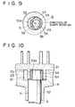
- FIG. 2 is a view for illustrating the relationship between the eccentric bush 54 and eccentric pin 53 in the above-described scroll-type compressor of the present invention, being viewed from above
- FIG. 3 is a sectional view for illustrating the relationship, viewed from the side.
- a part of the peripheral surface of the eccentric bush 54, which defines the inner peripheral surface or the hole 55, is formed as a flat portion 54a, and the flat portion 54a abuts on a flat portion 53b formed at a part of the outer peripheral surface of the eccentric pin 53, so that the eccentric bush 54 rotates integrally with the eccentric pin 53.
- a flat portion 54b is formed at the outer peripheral portion of the eccentric bush 54 opposing to the flat portion 54a substantially in the radial direction about 180° apart in the circumferential direction.
- This flat portion 54b defines an oil supply path (oil supply hole) 57 extending in the axial direction in cooperation with the orbiting bearing 73.
- the upper end of the oil supply path 57 is open at the upper end face of the eccentric bush 54 and the lower end thereof is open to the oil reservoir 61.
- the upper end face of the eccentric bush 54 is cut or removed to form a flat portion as indicated by 54d over the total wall thickness in the radial direction of the eccentric bush 54 from one end 54c of the flat portion 54b on the upstream side with respect to the direction of rotation of the rotating shaft 5 indicated by the arrow to a portion corresponding to the substantially intermediate position in the circumferential direction of the flat portion 54a (left side portion in FIG. 2), in other words, over an angular range of about 180° in the circumferential direction.
- the cut region is expanded as compared with FIG. 9.
- the lubricating oil discharged from the oil supply hole 52 at the upper end face of the eccentric bush 54 is not pushed toward the outer periphery of the eccentric bush 54 by a centrifugal force at the flat portion 54d, and is supplied efficiently to the oil supply path 57 by being blocked by bearing 73. Thereby, the amount of oil supplied to the oil supply path 57 is increased significantly.
- the upper end face of the eccentric bush 54 is not cut in nearly the same manner as in FIG. 9 from one end 54c of the flat portion 54b on the upstream side with respect to the direction of rotation of the rotating shaft 5 indicated by the arrow to a portion corresponding to the substantially intermediate position in the circumferential direction of the opposing flat portion 54a (right side portion in FIG.
- annular protrusion 54g is provided on the upper end face of the eccentric bush 54 along the whole upper edge of the inner periphery of the hole 55.
- the other portion on the upper end face is cut to form a flat portion (outer peripheral portion) 54h lower than the protrusion 54g (this flat portion defines an annular concave in consequence in cooperation with the surrounding orbiting bearing 73).
- the upper end face of this protrusion 54g is flush with the upper end face of the eccentric pin 53.
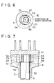
- FIGS. 6 and 7 only a configuration different from that of the first embodiment will be described.
- the whole of the upper end face of the eccentric bush 54 is made flat, so that the lubricating oil is allowed to flow into the gap 58.
- an annular flat plate (flat plate member) 59 with a suitable thickness and size is interposed between the lower end face of the eccentric bush 54 and the upper end shoulder 5a of the rotating shaft 5 so as to substantially cover the lower end of the gap 58.
- the lubricating oil flowing out of the oil supply hole 52 at the upper end face of the eccentric bush 54 part thereof flowing into the gap 58 is stored in the gap 58 without dropping into the oil reservoir 61.
- the lubricating oil is discharged upward from the gap 58, and supplied to the oil supply path 57 together with the lubricating oil released from the oil supply hole 52 to the upper end face of the eccentric bush 54.
- the discharge amount to the oil supply path 57 is increased significantly.
- the upper end face of the eccentric bush 54 is flush with the upper end face of the eccentric pin 53, but this is not always necessary. It may be terminated at a position below or above the upper end face of the eccentric pin 53.
Landscapes
- Engineering & Computer Science (AREA)
- Mechanical Engineering (AREA)
- General Engineering & Computer Science (AREA)
- Rotary Pumps (AREA)
- Applications Or Details Of Rotary Compressors (AREA)
Priority Applications (2)
| Application Number | Priority Date | Filing Date | Title |
|---|---|---|---|
| EP02023922A EP1277961B1 (de) | 1996-09-06 | 1997-07-04 | Spiralverdichter |
| EP02023923A EP1277962B1 (de) | 1996-09-06 | 1997-07-04 | Spiralverdichter |
Applications Claiming Priority (3)
| Application Number | Priority Date | Filing Date | Title |
|---|---|---|---|
| JP23673796 | 1996-09-06 | ||
| JP8236737A JP2915852B2 (ja) | 1996-09-06 | 1996-09-06 | スクロール型圧縮機 |
| JP236737/96 | 1996-09-06 |
Related Child Applications (2)
| Application Number | Title | Priority Date | Filing Date |
|---|---|---|---|
| EP02023923A Division EP1277962B1 (de) | 1996-09-06 | 1997-07-04 | Spiralverdichter |
| EP02023922A Division EP1277961B1 (de) | 1996-09-06 | 1997-07-04 | Spiralverdichter |
Publications (3)
| Publication Number | Publication Date |
|---|---|
| EP0828078A2 true EP0828078A2 (de) | 1998-03-11 |
| EP0828078A3 EP0828078A3 (de) | 1998-08-26 |
| EP0828078B1 EP0828078B1 (de) | 2003-06-04 |
Family
ID=17005045
Family Applications (3)
| Application Number | Title | Priority Date | Filing Date |
|---|---|---|---|
| EP02023922A Expired - Lifetime EP1277961B1 (de) | 1996-09-06 | 1997-07-04 | Spiralverdichter |
| EP02023923A Expired - Lifetime EP1277962B1 (de) | 1996-09-06 | 1997-07-04 | Spiralverdichter |
| EP97304903A Expired - Lifetime EP0828078B1 (de) | 1996-09-06 | 1997-07-04 | Spiralverdichter |
Family Applications Before (2)
| Application Number | Title | Priority Date | Filing Date |
|---|---|---|---|
| EP02023922A Expired - Lifetime EP1277961B1 (de) | 1996-09-06 | 1997-07-04 | Spiralverdichter |
| EP02023923A Expired - Lifetime EP1277962B1 (de) | 1996-09-06 | 1997-07-04 | Spiralverdichter |
Country Status (5)
| Country | Link |
|---|---|
| US (2) | US6012911A (de) |
| EP (3) | EP1277961B1 (de) |
| JP (1) | JP2915852B2 (de) |
| CN (1) | CN1078312C (de) |
| DE (3) | DE69732672T2 (de) |
Families Citing this family (19)
| Publication number | Priority date | Publication date | Assignee | Title |
|---|---|---|---|---|
| US6722228B1 (en) | 2000-12-28 | 2004-04-20 | Curt Wilkinson | Flywheel and method and apparatus for manufacturing flywheels |
| US6471499B1 (en) * | 2001-09-06 | 2002-10-29 | Scroll Technologies | Scroll compressor with lubrication directed to drive flat surfaces |
| KR100425740B1 (ko) * | 2002-02-09 | 2004-04-01 | 엘지전자 주식회사 | 스크롤 압축기의 마찰손실 저감장치 |
| US7044717B2 (en) | 2002-06-11 | 2006-05-16 | Tecumseh Products Company | Lubrication of a hermetic carbon dioxide compressor |
| CN100455804C (zh) * | 2002-11-20 | 2009-01-28 | 乐金电子(天津)电器有限公司 | 涡旋压缩机的减少磨损装置 |
| JP2005140066A (ja) * | 2003-11-10 | 2005-06-02 | Hitachi Ltd | 流体圧縮機 |
| KR100534571B1 (ko) * | 2003-12-16 | 2005-12-08 | 엘지전자 주식회사 | 스크롤 압축기의 슬라이드 부시 |
| US7556482B2 (en) * | 2005-06-29 | 2009-07-07 | Trane International Inc. | Scroll compressor with enhanced lubrication |
| JP4832040B2 (ja) * | 2005-09-20 | 2011-12-07 | 三洋電機株式会社 | 圧縮機 |
| US7901194B2 (en) * | 2008-04-09 | 2011-03-08 | Hamilton Sundstrand Corporation | Shaft coupling for scroll compressor |
| KR101849138B1 (ko) * | 2012-01-04 | 2018-04-16 | 엘지전자 주식회사 | 회전축 삽입부를 갖는 스크롤 압축기 및 그 제조방법 |
| CN103422981B (zh) * | 2012-05-21 | 2016-03-23 | 北京星旋世纪科技有限公司 | 星旋式流体机械及其应用的发动机和流体马达 |
| CN104343662B (zh) * | 2013-07-29 | 2018-02-16 | 青岛海尔智能技术研发有限公司 | 直线压缩机的供油方法、供油装置及直线压缩机 |
| US9453535B2 (en) | 2014-01-06 | 2016-09-27 | Hamilton Sundstrand Corporation | Oil retention and delivery system for a bearing |
| WO2016170615A1 (ja) * | 2015-04-22 | 2016-10-27 | 三菱電機株式会社 | スクロール圧縮機 |
| JP6550274B2 (ja) * | 2015-06-11 | 2019-07-24 | 株式会社ニッキ | 燃料供給装置 |
| CN110360103B (zh) * | 2019-07-17 | 2020-12-25 | 珠海格力节能环保制冷技术研究中心有限公司 | 涡旋压缩机、空调器及车辆 |
| CN114165437A (zh) * | 2020-09-11 | 2022-03-11 | 艾默生环境优化技术(苏州)有限公司 | 涡旋压缩机 |
| CN115875259A (zh) * | 2021-09-29 | 2023-03-31 | 艾默生环境优化技术(苏州)有限公司 | 涡旋压缩机 |
Family Cites Families (12)
| Publication number | Priority date | Publication date | Assignee | Title |
|---|---|---|---|---|
| JPS5865986A (ja) * | 1981-10-14 | 1983-04-19 | Hitachi Ltd | スクロ−ル圧縮機 |
| JPS60178988A (ja) * | 1984-02-24 | 1985-09-12 | Hitachi Ltd | スクロ−ル流体装置 |
| US5197868A (en) * | 1986-08-22 | 1993-03-30 | Copeland Corporation | Scroll-type machine having a lubricated drive bushing |
| US4997349A (en) * | 1989-10-05 | 1991-03-05 | Tecumseh Products Company | Lubrication system for the crank mechanism of a scroll compressor |
| JPH0826860B2 (ja) * | 1989-12-04 | 1996-03-21 | 三菱電機株式会社 | スクロール圧縮機 |
| JP2689659B2 (ja) * | 1989-12-04 | 1997-12-10 | 三菱電機株式会社 | スクロール圧縮機 |
| JPH0412186A (ja) | 1990-04-28 | 1992-01-16 | Mitsubishi Electric Corp | スクロール型流体装置 |
| DE69121026T2 (de) * | 1990-07-31 | 1996-12-19 | Copeland Corp | Schmiereinrichtung für Spiralmaschine |
| JP3175185B2 (ja) | 1991-04-25 | 2001-06-11 | ソニー株式会社 | 真空吸着装置および真空吸着装置の制御方法 |
| JP3175188B2 (ja) | 1991-05-10 | 2001-06-11 | ソニー株式会社 | 位置合わせマークの形成方法 |
| JP3137507B2 (ja) * | 1993-08-30 | 2001-02-26 | 三菱重工業株式会社 | スクロ−ル型流体機械 |
| JP3426720B2 (ja) * | 1994-07-26 | 2003-07-14 | 三菱重工業株式会社 | スクロール型圧縮機およびその製造方法 |
-
1996
- 1996-09-06 JP JP8236737A patent/JP2915852B2/ja not_active Expired - Lifetime
-
1997
- 1997-05-30 US US08/866,495 patent/US6012911A/en not_active Expired - Lifetime
- 1997-07-04 DE DE69732672T patent/DE69732672T2/de not_active Expired - Lifetime
- 1997-07-04 DE DE69730630T patent/DE69730630T2/de not_active Expired - Lifetime
- 1997-07-04 EP EP02023922A patent/EP1277961B1/de not_active Expired - Lifetime
- 1997-07-04 EP EP02023923A patent/EP1277962B1/de not_active Expired - Lifetime
- 1997-07-04 EP EP97304903A patent/EP0828078B1/de not_active Expired - Lifetime
- 1997-07-04 DE DE69722539T patent/DE69722539T2/de not_active Expired - Lifetime
- 1997-07-18 CN CN97114705A patent/CN1078312C/zh not_active Expired - Lifetime
-
1999
- 1999-12-17 US US09/464,819 patent/US6361296B1/en not_active Expired - Lifetime
Also Published As
| Publication number | Publication date |
|---|---|
| EP1277961A2 (de) | 2003-01-22 |
| DE69732672D1 (de) | 2005-04-07 |
| EP1277962B1 (de) | 2004-09-08 |
| DE69732672T2 (de) | 2005-12-29 |
| EP1277962A2 (de) | 2003-01-22 |
| US6012911A (en) | 2000-01-11 |
| EP1277961A3 (de) | 2003-03-19 |
| CN1176350A (zh) | 1998-03-18 |
| EP0828078A3 (de) | 1998-08-26 |
| DE69722539D1 (de) | 2003-07-10 |
| US6361296B1 (en) | 2002-03-26 |
| CN1078312C (zh) | 2002-01-23 |
| JP2915852B2 (ja) | 1999-07-05 |
| EP1277961B1 (de) | 2005-03-02 |
| DE69730630T2 (de) | 2005-09-15 |
| EP1277962A3 (de) | 2003-03-19 |
| EP0828078B1 (de) | 2003-06-04 |
| DE69722539T2 (de) | 2004-04-22 |
| DE69730630D1 (de) | 2004-10-14 |
| JPH1082383A (ja) | 1998-03-31 |
Similar Documents
| Publication | Publication Date | Title |
|---|---|---|
| US6012911A (en) | Scroll type compressor having an oil supply path for the eccentric bearing | |
| US6106254A (en) | Closed-type scroll compressor | |
| US5314316A (en) | Scroll apparatus with reduced inlet pressure drop | |
| KR101472819B1 (ko) | 정렬 특성이 있는 쉘을 가지는 컴프레서 | |
| US6106251A (en) | Scroll machine with reverse rotation sound attenuation | |
| EP0717192B1 (de) | Ölstandskontrollvorrichtung für kompressoren | |
| JPH05149269A (ja) | スクロール型流体機械 | |
| US5375986A (en) | Oil pump for a closed type compressor | |
| JPH05149274A (ja) | スクロール式圧縮機 | |
| JP3132347B2 (ja) | スクロール形流体機械 | |
| JP3207825B2 (ja) | スクロール型流体機械 | |
| JPH0942177A (ja) | スクロール圧縮機 | |
| JP2766291B2 (ja) | スクロール式圧縮機 | |
| JP7468428B2 (ja) | スクロール型圧縮機 | |
| JP2537544Y2 (ja) | 密閉型圧縮機の油ポンプ | |
| JP3128317B2 (ja) | スクロール圧縮機 | |
| JP3101442B2 (ja) | スクロール圧縮機の給油装置 | |
| JPH0949493A (ja) | スクロール圧縮機 | |
| JP3555273B2 (ja) | スクロール形流体機械 | |
| JPH08105392A (ja) | スクロール型圧縮機 | |
| JPH0771386A (ja) | スクロ−ル型流体機械 | |
| JP2003129974A (ja) | スクロール型圧縮機 | |
| JPH0861278A (ja) | 横置型スクロール圧縮機 | |
| JPH0771387A (ja) | 密閉型圧縮機の油ポンプ | |
| JPH08219061A (ja) | スクロール型コンプレッサ |
Legal Events
| Date | Code | Title | Description |
|---|---|---|---|
| PUAI | Public reference made under article 153(3) epc to a published international application that has entered the european phase |
Free format text: ORIGINAL CODE: 0009012 |
|
| AK | Designated contracting states |
Kind code of ref document: A2 Designated state(s): DE FR GB |
|
| AX | Request for extension of the european patent |
Free format text: AL;LT;LV;RO;SI |
|
| PUAL | Search report despatched |
Free format text: ORIGINAL CODE: 0009013 |
|
| AK | Designated contracting states |
Kind code of ref document: A3 Designated state(s): AT BE CH DE DK ES FI FR GB GR IE IT LI LU MC NL PT SE |
|
| AX | Request for extension of the european patent |
Free format text: AL;LT;LV;RO;SI |
|
| 17P | Request for examination filed |
Effective date: 19990129 |
|
| AKX | Designation fees paid |
Free format text: DE FR GB |
|
| RBV | Designated contracting states (corrected) |
Designated state(s): DE FR GB |
|
| 17Q | First examination report despatched |
Effective date: 20010921 |
|
| GRAH | Despatch of communication of intention to grant a patent |
Free format text: ORIGINAL CODE: EPIDOS IGRA |
|
| GRAH | Despatch of communication of intention to grant a patent |
Free format text: ORIGINAL CODE: EPIDOS IGRA |
|
| GRAA | (expected) grant |
Free format text: ORIGINAL CODE: 0009210 |
|
| AK | Designated contracting states |
Designated state(s): DE FR GB |
|
| REG | Reference to a national code |
Ref country code: GB Ref legal event code: FG4D |
|
| REF | Corresponds to: |
Ref document number: 69722539 Country of ref document: DE Date of ref document: 20030710 Kind code of ref document: P |
|
| REG | Reference to a national code |
Ref country code: GB Ref legal event code: 746 Effective date: 20031111 |
|
| ET | Fr: translation filed | ||
| PLBE | No opposition filed within time limit |
Free format text: ORIGINAL CODE: 0009261 |
|
| STAA | Information on the status of an ep patent application or granted ep patent |
Free format text: STATUS: NO OPPOSITION FILED WITHIN TIME LIMIT |
|
| 26N | No opposition filed |
Effective date: 20040305 |
|
| PGFP | Annual fee paid to national office [announced via postgrant information from national office to epo] |
Ref country code: FR Payment date: 20050708 Year of fee payment: 9 |
|
| REG | Reference to a national code |
Ref country code: FR Ref legal event code: ST Effective date: 20070330 |
|
| PG25 | Lapsed in a contracting state [announced via postgrant information from national office to epo] |
Ref country code: FR Free format text: LAPSE BECAUSE OF NON-PAYMENT OF DUE FEES Effective date: 20060731 |
|
| PGFP | Annual fee paid to national office [announced via postgrant information from national office to epo] |
Ref country code: GB Payment date: 20160629 Year of fee payment: 20 |
|
| PGFP | Annual fee paid to national office [announced via postgrant information from national office to epo] |
Ref country code: DE Payment date: 20160628 Year of fee payment: 20 |
|
| REG | Reference to a national code |
Ref country code: DE Ref legal event code: R071 Ref document number: 69722539 Country of ref document: DE |
|
| REG | Reference to a national code |
Ref country code: GB Ref legal event code: PE20 Expiry date: 20170703 |
|
| PG25 | Lapsed in a contracting state [announced via postgrant information from national office to epo] |
Ref country code: GB Free format text: LAPSE BECAUSE OF EXPIRATION OF PROTECTION Effective date: 20170703 |