EP0827258B1 - Device for supporting rotating shaft and small-sized motor - Google Patents
Device for supporting rotating shaft and small-sized motor Download PDFInfo
- Publication number
- EP0827258B1 EP0827258B1 EP97902684A EP97902684A EP0827258B1 EP 0827258 B1 EP0827258 B1 EP 0827258B1 EP 97902684 A EP97902684 A EP 97902684A EP 97902684 A EP97902684 A EP 97902684A EP 0827258 B1 EP0827258 B1 EP 0827258B1
- Authority
- EP
- European Patent Office
- Prior art keywords
- rotating shaft
- support member
- main body
- bracket main
- shaft support
- Prior art date
- Legal status (The legal status is an assumption and is not a legal conclusion. Google has not performed a legal analysis and makes no representation as to the accuracy of the status listed.)
- Expired - Lifetime
Links
- 230000002093 peripheral effect Effects 0.000 claims description 22
- 229920000106 Liquid crystal polymer Polymers 0.000 claims description 18
- 239000004977 Liquid-crystal polymers (LCPs) Substances 0.000 claims description 18
- 239000000463 material Substances 0.000 claims description 15
- 239000011347 resin Substances 0.000 claims description 11
- 229920005989 resin Polymers 0.000 claims description 11
- 238000001746 injection moulding Methods 0.000 claims description 7
- 230000001050 lubricating effect Effects 0.000 claims description 3
- 239000007787 solid Substances 0.000 claims description 2
- 239000000853 adhesive Substances 0.000 description 6
- 239000004519 grease Substances 0.000 description 5
- WABPQHHGFIMREM-UHFFFAOYSA-N lead(0) Chemical compound [Pb] WABPQHHGFIMREM-UHFFFAOYSA-N 0.000 description 5
- 239000000470 constituent Substances 0.000 description 4
- 239000000314 lubricant Substances 0.000 description 3
- 229910052751 metal Inorganic materials 0.000 description 3
- 239000002184 metal Substances 0.000 description 3
- 239000004734 Polyphenylene sulfide Substances 0.000 description 2
- 239000000945 filler Substances 0.000 description 2
- 239000000696 magnetic material Substances 0.000 description 2
- 229920000642 polymer Polymers 0.000 description 2
- 229920000069 polyphenylene sulfide Polymers 0.000 description 2
- -1 polytetrafluoroethylene Polymers 0.000 description 2
- 229910052761 rare earth metal Inorganic materials 0.000 description 2
- OKTJSMMVPCPJKN-UHFFFAOYSA-N Carbon Chemical compound [C] OKTJSMMVPCPJKN-UHFFFAOYSA-N 0.000 description 1
- 229930182556 Polyacetal Natural products 0.000 description 1
- 239000004952 Polyamide Substances 0.000 description 1
- 239000004642 Polyimide Substances 0.000 description 1
- 229910000831 Steel Inorganic materials 0.000 description 1
- 239000000654 additive Substances 0.000 description 1
- 229910045601 alloy Inorganic materials 0.000 description 1
- 239000000956 alloy Substances 0.000 description 1
- 230000015572 biosynthetic process Effects 0.000 description 1
- 239000000919 ceramic Substances 0.000 description 1
- 238000004891 communication Methods 0.000 description 1
- 229920001577 copolymer Polymers 0.000 description 1
- 230000006866 deterioration Effects 0.000 description 1
- 238000010586 diagram Methods 0.000 description 1
- 239000000428 dust Substances 0.000 description 1
- 239000003365 glass fiber Substances 0.000 description 1
- 229910002804 graphite Inorganic materials 0.000 description 1
- 239000010439 graphite Substances 0.000 description 1
- 238000009499 grossing Methods 0.000 description 1
- 239000004615 ingredient Substances 0.000 description 1
- 238000002347 injection Methods 0.000 description 1
- 239000007924 injection Substances 0.000 description 1
- 239000011256 inorganic filler Substances 0.000 description 1
- 229910003475 inorganic filler Inorganic materials 0.000 description 1
- 238000003780 insertion Methods 0.000 description 1
- 230000037431 insertion Effects 0.000 description 1
- 238000012423 maintenance Methods 0.000 description 1
- 238000004519 manufacturing process Methods 0.000 description 1
- 239000000155 melt Substances 0.000 description 1
- 239000007769 metal material Substances 0.000 description 1
- 238000000465 moulding Methods 0.000 description 1
- 239000000049 pigment Substances 0.000 description 1
- 229920002647 polyamide Polymers 0.000 description 1
- 229920000515 polycarbonate Polymers 0.000 description 1
- 239000004417 polycarbonate Substances 0.000 description 1
- 229920001721 polyimide Polymers 0.000 description 1
- 229920002959 polymer blend Polymers 0.000 description 1
- 229920006324 polyoxymethylene Polymers 0.000 description 1
- 229920001343 polytetrafluoroethylene Polymers 0.000 description 1
- 239000004810 polytetrafluoroethylene Substances 0.000 description 1
- 229910000938 samarium–cobalt magnet Inorganic materials 0.000 description 1
- 239000010935 stainless steel Substances 0.000 description 1
- 229910001220 stainless steel Inorganic materials 0.000 description 1
- 239000010959 steel Substances 0.000 description 1
- 229910052723 transition metal Inorganic materials 0.000 description 1
- 150000003624 transition metals Chemical class 0.000 description 1
- 238000004804 winding Methods 0.000 description 1
Images


Classifications
-
- H—ELECTRICITY
- H02—GENERATION; CONVERSION OR DISTRIBUTION OF ELECTRIC POWER
- H02K—DYNAMO-ELECTRIC MACHINES
- H02K5/00—Casings; Enclosures; Supports
- H02K5/04—Casings or enclosures characterised by the shape, form or construction thereof
- H02K5/16—Means for supporting bearings, e.g. insulating supports or means for fitting bearings in the bearing-shields
- H02K5/167—Means for supporting bearings, e.g. insulating supports or means for fitting bearings in the bearing-shields using sliding-contact or spherical cap bearings
- H02K5/1672—Means for supporting bearings, e.g. insulating supports or means for fitting bearings in the bearing-shields using sliding-contact or spherical cap bearings radially supporting the rotary shaft at both ends of the rotor
-
- H—ELECTRICITY
- H02—GENERATION; CONVERSION OR DISTRIBUTION OF ELECTRIC POWER
- H02K—DYNAMO-ELECTRIC MACHINES
- H02K5/00—Casings; Enclosures; Supports
- H02K5/04—Casings or enclosures characterised by the shape, form or construction thereof
- H02K5/08—Insulating casings
-
- H—ELECTRICITY
- H02—GENERATION; CONVERSION OR DISTRIBUTION OF ELECTRIC POWER
- H02K—DYNAMO-ELECTRIC MACHINES
- H02K5/00—Casings; Enclosures; Supports
- H02K5/04—Casings or enclosures characterised by the shape, form or construction thereof
- H02K5/14—Means for supporting or protecting brushes or brush holders
- H02K5/143—Means for supporting or protecting brushes or brush holders for cooperation with commutators
- H02K5/145—Fixedly supported brushes or brush holders, e.g. leaf or leaf-mounted brushes
-
- H—ELECTRICITY
- H02—GENERATION; CONVERSION OR DISTRIBUTION OF ELECTRIC POWER
- H02K—DYNAMO-ELECTRIC MACHINES
- H02K5/00—Casings; Enclosures; Supports
- H02K5/04—Casings or enclosures characterised by the shape, form or construction thereof
- H02K5/22—Auxiliary parts of casings not covered by groups H02K5/06-H02K5/20, e.g. shaped to form connection boxes or terminal boxes
- H02K5/225—Terminal boxes or connection arrangements
Definitions
- the present invention relates to a rotating shaft support member and a small motor equipped with the same.
- a motor has a casing, and a stator and a rotor installed in the casing; the rotor is rotatably supported by brackets installed at both ends of the casing.
- the rotating shaft of the rotor is supported by appropriate oil-retaining bearings composed of a sintered metal impregnated with, for example, 18 vol% of a lubricant, and the bearings are fitted in and fixed at the center inside the resinous brackets.
- brackets and bearings which are separate members, are assembled and the number of the components accordingly increases, requiring time and effort for the assembling operation, especially for positioning the bearings relative to the brackets.
- EP-A-0 168 743 discloses a rotating shaft support member for supporting a rotating shaft, said rotating shaft support member having a bracket main body.
- This bracket main body is provided with a bearing unit which rotatably supports an end of said rotating shaft and wherein the bearing unit has a bottomed shaft bore having an inner peripheral surface and a bottom surface which are in contact with the outer peripheral surface of the rotating shaft.
- This prior art document also describes a small motor comprising a casing with an end section equipped with said rotating shaft suppor member and further comprising a rotor which is rotatably supported by said rotating shaft support member and a stator provided on the outer peripheral section of said rotor.
- bracket main body and casing with a permanent magnet clipable means are used and through holes for passing a lead wire are provided in the bearing unit.
- the members of the small motor are composed of a resign material.
- Patent abstracts of Japan Vol. 012, No. 351 discloses a small motor comprising a rotor, a rotating shaft support member, rotating shaft, a bearing unit and a bracket main body.
- the prior art motor includes further a grease reservoir part in which grease is packed by using grease container wherein the grease is pressed in a direction of a bearing hole of said rotating shaft.
- the rotating shaft support member and the small motor including the bearing unit formed as claimed in claim 1 makes it possible to reduce the number of parts and to simplify the assembly operation.
- the bearing units of the bracket main body are composed of a resin having lubricating properties which is represented by a liquid crystal polymer
- the sliding resistance of the rotating shaft with respect to a shaft bore is reduced, enabling reduced loss in motor torque.
- composing the bearing units by using a liquid crystal polymer permits improved quietness while the motor is running, and better durability and better formability of the bearing units, and also makes it possible to obtain molded articles with extremely high dimensional accuracy of each component and especially of the inside diameter and depth of the shaft bore.
- the holding force for the lead wire passed through the through hole can be improved, allowing the lead wire from being slipped off.
- the small motor in accordance with the present invention can be applied to a pager unit, portable telephone, camera, portable tape recorder, etc.
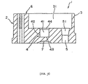
- a rotating shaft support member 1 is composed of a bracket main body 2 which is nearly circular.
- An outer peripheral wall 3 is provided on the outer periphery of the bracket main body 2; at the central portion of the bracket main body 2, a bearing unit 4 which rotatably supports an end of a rotating shaft 133 of a rotor 13 (see Fig. 3), which will be discussed later, is formed integrally with the bracket main body 2.
- the bearing unit 4 has a shaft bore 41 in which the rotating shaft 133 of the rotor 13 is inserted.
- the shaft bore 41 has an inner peripheral surface 42 in contact with the outer peripheral surface of the rotating shaft 13 and a bottom surface 43 abutting an end surface of the rotating shaft 133; it is opened to and in communication with a space 31 surrounded by the outer peripheral wall 3.
- the inner peripheral surface 42 constitutes a cylindrical surface, the inside diameter of which is almost constant in the axial direction; and the bottom surface 43 constitutes a plane.
- a tapered or guiding surface 44 Formed at the top of the inner peripheral surface 42 of the shaft bore 41 in Fig. 2 is a tapered or guiding surface 44 which diverges toward the space 31 to permit easy insertion of the rotating shaft 133.
- the inside diameter of the inner peripheral surface 42 of the shaft bore 41 is preferably about 0.3 to about 1.5 mm, more preferably about 0.6 to about 0.8 mm, and the depth of the shaft bore 41 is preferably about 0.5 to about 1.5 mm and more preferably about 0.6 to about 0.8 mm.
- the shape of the shaft bore 41 is not limited to that shown in the figure; for example, the shape may alternatively be a tapered surface or a surface having a step which is formed by all or a part of the inner peripheral surface 42 with the inside diameter thereof gradually increasing toward the space 31; and the bottom surface 43 may be a surface which has a convex or concave curved surface or a surface having a step.
- bracket main body 2 a pair of through holes 5 which penetrate the bracket main body 2 are formed at the positions opposed to each other with the bearing unit 4 serving as the midpoint therebetween. Lead wires 15 which supply electric power for rotationally driving the rotor 13 are passed through these through holes 5.
- the inside diameter of the bottom portions of the through holes 5 shown in Fig. 2 is set so that it is equal to or slightly larger than the outside diameter of the lead wires 15 provided with sheaths; it is made constant in the axial directions of the through holes 5.
- Formed at the top of the through holes 5 shown in Fig. 2 are portions having an inside diameter which gradually increases toward the space 31 inside the bracket main body, namely, tapered portions 51 which diverge toward the space 31.
- the tapered portions 51 constitute the adhesive agent reservoirs that are filled with an adhesive agent 16, which will be discussed later, with the lead wires 15 passed through the through holes 5; however, they are not necessarily filled with the adhesive agent 16 or other fixing member.
- a brush fixing section 6 for fixing a brush 17, which will be discussed later, is formed integrally with the bracket main body 2.
- the foregoing bracket main body 2 is preferably composed of a resin material which intrinsically has lubricating properties and, more particularly, a resin material which has a relatively low friction coefficient and wear resistance.
- Such materials include, for example, liquid crystal polymer (LCP), polytetrafluoroethylene, polyphenylenesulfide (PPS), polyamide, polyimide, polyacetal, and polycarbonate; an especially preferred material contains a liquid crystal polymer as the principal ingredient.
- LCP liquid crystal polymer
- PPS polyphenylenesulfide
- polyamide polyamide
- polyimide polyimide
- polyacetal polycarbonate
- an especially preferred material contains a liquid crystal polymer as the principal ingredient.
- a liquid crystal polymer has high mechanical strength, a low friction coefficient, and high wear resistance, thus making it advantageous for the rotating shaft 133 to slide against the inner peripheral surface 42 or the bottom surface 43 of the shaft bore 41; it is especially effective for suppressing sliding noises or vibration noises, so that it contributes to improved quietness.
- a liquid crystal polymer exhibits high fluidity when it melts and has good formability when the bracket main body 2 is manufactured by, for example, injection molding; hence, a liquid crystal polymer is suited also for forming, for example, a minute and complicated shape, or a thin part such as the outer peripheral wall 3, and it develops fewer burrs.
- a liquid crystal polymer shows less structural difference between solid and melt, so that the mold shrinkage factor is low, thus making it possible to obtain moldings with extremely high dimensional accuracy of every component, particularly the inside diameter and depth of the shaft bore 41.
- Liquid crystal polymers are classified into type I, type II, and type III according to the thermal deformation temperature thereof, among which liquid crystal polymers of type II (the thermal deformation temperature is about 200 to 300 degrees Celsius) are especially preferable because they show the foregoing advantage more markedly.
- the type II liquid crystal polymer suitably used is Vectra (trade name) made by Polyplastics.
- the constituent material for the bracket main body 2 is not limited to a liquid crystal polymer alone; it may be a copolymer of a liquid crystal polymer and other polymer, a polymer blend or polymer alloy containing a liquid crystal polymer, etc. Further, for various purposes, diverse additives such as a filler and a pigment may be added to the material. For instance, adding a filler (e.g. an inorganic filler such as graphite, glass fiber, etc.) is advantageous for easing the anisotropy of a liquid crystal polymer.
- a filler e.g. an inorganic filler such as graphite, glass fiber, etc.
- the constituent material of the bracket main body 2 represented by the foregoing liquid crystal polymers preferably has a mold shrinkage factor of 0.5% or less. This enables the formation of the shaft bore 41 having extremely high dimensional accuracy.
- the bracket main body 2 is fabricated by injection molding.
- the injection molding makes it possible to manufacture the bracket main body 2 having a complicated shape with good dimensional accuracy and high productivity.
- the bracket main body 2 manufactured by injection molding is preferably provided with a gate trace 8 for the injection of resin, said gate trace 8 being formed near the bottom of the shaft bore 41 of the bracket main body 2.
- a dish-shaped depression 7 is formed at a position on the extension of the shaft bore 41 at the bottom surface of the bracket main body 2; the gate trace 8 is formed in the depression 7, specifically near the center of the depression 7, at a position which approximately aligns with the axis of the shaft bore 41.
- the dimension of the bracket main body 2 is not limited in particular; however, if it is used for a small motor which will be discussed later, then the outside diameter of the bracket main body 2 is preferably about 2 to about 15 mm and more preferably about 2 to about 6 mm.
- a small motor 10 in accordance with the present invention shown in Fig. 3 is preferably a DC motor; it has a cylindrical trunk 12 and a casing 11 comprised of rotating shaft support members attached to both ends of the trunk 12.
- the rotating shaft support member on the side of the bottom end of the casing 11 in Fig. 3 is the rotating shaft support member 1 mentioned previously, while the rotating shaft support member (not shown) on the side of the top end in Fig. 3 is the same as the rotating shaft support member 1 except that it is not provided with the through holes 5 and the brush fixing sections 6.
- the rotor 13 is rotatably supported by both rotating shaft support members 1.
- the rotor 13 is comprised of a core 131, a pair of exciting coils 132 formed by providing the core 131 with a winding, the rotating shaft 133 fitted at the center of the core 131, and a commutator 134; both ends of the rotating shaft 133 are respectively inserted in the shaft bores 41 of the rotating shaft support members 1 so as to be rotatably supported with respect to the casing 11.
- the end surface of the rotating shaft 133 constitutes a curved convex surface which is in contact with the bottom surface 43 of the shaft bore 41 through a small area (point contact). This reduces the frictional force when the rotor 13 rotates.
- a material which has high strength and a low coefficient of friction is preferred, such as a metal material including stainless steel (SUS) and bearing steel (SUJ) or ceramics.
- the portion in contact with at least the shaft bore 41 of the rotating shaft 133 is provided with smoothing treatment for reducing the roughness of the surface.
- the commutator 134 has a structure wherein a pair of commutator pieces which are isolated from each other are disposed against each other; the respective commutator pieces are electrically connected to corresponding exciting coils 132. This causes commutation at every 180 degrees of rotational angle when the rotor 13 rotates.
- the permanent magnets 14 On the outer periphery of the portion where the exciting coils 132 of the rotor 13 are disposed, permanent magnets (stator magnets) 14 fixed on the inner surface of the trunk 12 are installed as stators.
- the permanent magnets 14 may be either cylindrical magnets or segment type (split type) magnets.
- the magnetic material constituting the permanent magnets 14 there are no particular restrictions on the magnetic material constituting the permanent magnets 14; however, it is preferred to use a magnetic material which contains a rare earth element and a transition metal (e.g. SmCo type magnet, R-Fe-B type magnet, wherein "R” is a rare earth element containing Y) because it exhibits good magnetic properties.
- a magnetic material which contains a rare earth element and a transition metal e.g. SmCo type magnet, R-Fe-B type magnet, wherein "R” is a rare earth element containing Y
- the type of the permanent magnets 14 may be any of sintered magnets, cast magnets, resin-bonded magnets, etc., however, they are preferably resin-bonded magnets because of the good formability, etc. thereof.
- the lead wires 15 are respectively inserted in both through holes 5 of the rotating shaft support member 1 located at the bottom in Fig. 3; these lead wires 15 are glued and fixed to the bracket main body 2 by filling the tapered portions 51 with the adhesive agent 16.
- the through holes 5 are provided with the tapered portions 51, so that the solidified adhesive agent 16 produces an operation similar to that of a wedge to prevent disconnection caused by the lead wires 15 slipping out of the through holes 5.
- the brushes 17 composed of metallic sheet strips are respectively fixed on both fixing sections 6 of the rotating shaft support member 1 positioned at the bottom side in Fig. 3.
- the proximal ends of the respective brushes 17 are soldered to the metal wires 151 exposed from the corresponding lead wires 15.
- the distal ends (the ends on the side of the center of the bracket main body 2) of the respective brushes 17 are in contact with the outer periphery of the commutator 134 at the locations which are shifted from each other by a rotational angle of 180 degrees.
- the inner peripheral surface 42 and the bottom surface 43 of the shaft bore 42 supporting the rotating shaft 133 have low friction and good wear resistance, thus eliminating the need for filling the shaft bore 42 with lubricant.
- oil does not move along the outer peripheral surface of the rotating shaft 133 to adhere the commutator 134, etc. as it used to do in a case where a conventional oil bearing is employed, so that it is possible to prevent deterioration in the performance of the motor caused by contact failures, the adhesion of dust, etc. attributable to oil.
- the small motor in accordance with the present is not limited to a DC motor; it may alternatively be a single-phase AC motor or other phase AC motor.
- the rotating shaft support member and the small motor according to the present invention have been described in conjunction with the embodiment shown in the figures.
- the present invention is not limited thereto; for example, the shape of the entire rotating shaft support member or the shapes of the respective sections thereof, the disposition of the rotating shaft support member in the small motor, the number, the shape, and the dimension of the rotor, etc. are not limited to those of the foregoing embodiment.
Landscapes
- Engineering & Computer Science (AREA)
- Power Engineering (AREA)
- Motor Or Generator Frames (AREA)
- Sliding-Contact Bearings (AREA)
Applications Claiming Priority (4)
| Application Number | Priority Date | Filing Date | Title |
|---|---|---|---|
| JP28270/96 | 1996-02-15 | ||
| JP2827096 | 1996-02-15 | ||
| JP02827096A JP3650978B2 (ja) | 1996-02-15 | 1996-02-15 | 回転軸支持部材および小型モータ |
| PCT/JP1997/000393 WO1997030507A1 (fr) | 1996-02-15 | 1997-02-13 | Dispositif support pour arbre rotatif et moteur de petite taille |
Publications (3)
| Publication Number | Publication Date |
|---|---|
| EP0827258A1 EP0827258A1 (en) | 1998-03-04 |
| EP0827258A4 EP0827258A4 (en) | 2001-05-09 |
| EP0827258B1 true EP0827258B1 (en) | 2004-10-13 |
Family
ID=12243899
Family Applications (1)
| Application Number | Title | Priority Date | Filing Date |
|---|---|---|---|
| EP97902684A Expired - Lifetime EP0827258B1 (en) | 1996-02-15 | 1997-02-13 | Device for supporting rotating shaft and small-sized motor |
Country Status (6)
| Country | Link |
|---|---|
| US (1) | US6060807A (ja) |
| EP (1) | EP0827258B1 (ja) |
| JP (1) | JP3650978B2 (ja) |
| CA (1) | CA2216732C (ja) |
| DE (1) | DE69731158T2 (ja) |
| WO (1) | WO1997030507A1 (ja) |
Families Citing this family (6)
| Publication number | Priority date | Publication date | Assignee | Title |
|---|---|---|---|---|
| JP4739857B2 (ja) * | 2005-08-12 | 2011-08-03 | 東芝産業機器製造株式会社 | キャンドモータ用樹脂製キャン及びその製造方法、射出成形金型、キャンドモータ、キャンドモータポンプ |
| JP4597015B2 (ja) * | 2005-09-14 | 2010-12-15 | 日本電産サンキョー株式会社 | モータ |
| JP4694997B2 (ja) * | 2006-03-22 | 2011-06-08 | 日本電産サンキョー株式会社 | モータ |
| JP5465391B2 (ja) * | 2007-03-30 | 2014-04-09 | 日本電産サンキョー株式会社 | モータ |
| KR20090019433A (ko) * | 2007-08-21 | 2009-02-25 | 삼성전자주식회사 | 회전지지장치 및 그 조립방법 과 이를 구비한 감시용카메라 |
| JP5940813B2 (ja) * | 2012-01-17 | 2016-06-29 | シャープ株式会社 | 空気調和機 |
Family Cites Families (26)
| Publication number | Priority date | Publication date | Assignee | Title |
|---|---|---|---|---|
| US3583778A (en) * | 1968-10-03 | 1971-06-08 | Hideo Mori | Combination thrust-radial bearing |
| US4086510A (en) * | 1975-06-26 | 1978-04-25 | Olympus Optical Co., Ltd. | Flat miniature dynamoelectric machine |
| JPS55162359U (ja) * | 1979-05-10 | 1980-11-21 | ||
| JPS5762749A (en) * | 1980-10-03 | 1982-04-15 | Hitachi Ltd | Mold motor |
| JPS57195354U (ja) * | 1981-06-08 | 1982-12-10 | ||
| JPS5846258U (ja) * | 1981-09-24 | 1983-03-29 | 松下電器産業株式会社 | モ−ルドモ−タの口出し線装置 |
| FR2545664A3 (fr) * | 1983-05-04 | 1984-11-09 | Zanussi Elettromecc | Moteur pour electropompe |
| JPS60190159U (ja) * | 1984-05-28 | 1985-12-17 | キヤノン株式会社 | 軸受 |
| JPS60192683U (ja) * | 1984-05-30 | 1985-12-21 | 富士電気化学株式会社 | ステツパモ−タ用ステ−タ |
| DE3426126C2 (de) * | 1984-07-16 | 1987-04-30 | Braun Ag, 6000 Frankfurt | Stator für Gleichstrom-Kleinstmotoren |
| DE8428487U1 (de) * | 1984-09-27 | 1985-10-24 | Siemens AG, 1000 Berlin und 8000 München | Dauermagneterregter Kleinmotor |
| JPS63107437A (ja) * | 1986-10-23 | 1988-05-12 | Matsushita Electric Works Ltd | モ−タの軸受 |
| JP2633239B2 (ja) * | 1986-12-12 | 1997-07-23 | 松下電器産業株式会社 | モールドモータ |
| JPS6430435A (en) * | 1987-07-27 | 1989-02-01 | Fuji Electrochemical Co Ltd | Bearing structure for miniature motor |
| JPH02136053A (ja) * | 1988-11-16 | 1990-05-24 | Sanyo Electric Co Ltd | マイクロモータ |
| JPH03159534A (ja) * | 1989-11-14 | 1991-07-09 | Fujitsu General Ltd | 電動機 |
| JP2646512B2 (ja) * | 1991-12-25 | 1997-08-27 | アスモ株式会社 | 小型モータの樹脂注入軸受 |
| JPH05339475A (ja) * | 1992-04-08 | 1993-12-21 | Toray Ind Inc | 液晶性樹脂組成物 |
| JPH0678505A (ja) * | 1992-08-25 | 1994-03-18 | Seiko Instr Inc | 超小型モータ |
| US5268607A (en) * | 1992-09-09 | 1993-12-07 | Webster Plastics | Molded resin motor housing |
| JPH0688158U (ja) * | 1993-05-24 | 1994-12-22 | 愛三工業株式会社 | 樹脂モールドモータの防錆構造 |
| TW340130B (en) * | 1993-12-28 | 1998-09-11 | Toray Industries | Shaped article of liquid crystalline resin |
| US5731373A (en) * | 1994-12-26 | 1998-03-24 | Ntn Corporation | Slide bearing slide bearing assembly and small motor |
| JP3312370B2 (ja) * | 1995-03-28 | 2002-08-05 | ミネベア株式会社 | モ−タ構造 |
| US5644180A (en) * | 1995-06-06 | 1997-07-01 | Itt Automotive Electrical Systems, Inc. | Rear motor bearing for worm gear drive motors |
| TW413697B (en) * | 1995-12-15 | 2000-12-01 | Toray Industries | Liquid crystalline resin composition |
-
1996
- 1996-02-15 JP JP02827096A patent/JP3650978B2/ja not_active Expired - Lifetime
-
1997
- 1997-02-13 WO PCT/JP1997/000393 patent/WO1997030507A1/ja active IP Right Grant
- 1997-02-13 DE DE69731158T patent/DE69731158T2/de not_active Expired - Lifetime
- 1997-02-13 EP EP97902684A patent/EP0827258B1/en not_active Expired - Lifetime
- 1997-02-13 CA CA002216732A patent/CA2216732C/en not_active Expired - Fee Related
- 1997-02-13 US US08/952,049 patent/US6060807A/en not_active Expired - Lifetime
Also Published As
| Publication number | Publication date |
|---|---|
| US6060807A (en) | 2000-05-09 |
| JPH09224346A (ja) | 1997-08-26 |
| WO1997030507A1 (fr) | 1997-08-21 |
| DE69731158T2 (de) | 2006-02-23 |
| EP0827258A1 (en) | 1998-03-04 |
| CA2216732C (en) | 2004-05-11 |
| EP0827258A4 (en) | 2001-05-09 |
| DE69731158D1 (de) | 2004-11-18 |
| CA2216732A1 (en) | 1997-08-21 |
| JP3650978B2 (ja) | 2005-05-25 |
Similar Documents
| Publication | Publication Date | Title |
|---|---|---|
| US6342739B1 (en) | Small-sized motor and method of manufacturing the same | |
| US6844636B2 (en) | Spindle motor with encapsulated stator and method of making same | |
| JP2004236390A (ja) | 小型ブラシレスモータ | |
| US8928209B2 (en) | Motor and method of manufacturing the same | |
| US7029179B2 (en) | Bearing unit, and motor using same | |
| US4884000A (en) | Brushless DC motor inner tachometer | |
| US20010038250A1 (en) | Motor with rotator and rotor shaft and method for manufacturing motor | |
| JPH0944985A (ja) | 動圧軸受装置を使用したディスク駆動装置 | |
| EP0827258B1 (en) | Device for supporting rotating shaft and small-sized motor | |
| US20040000828A1 (en) | Motor with resin base plate | |
| EP0676850B1 (en) | Miniature electric motor having bearing unit | |
| US20030001451A1 (en) | Eccentric rotor having high density member, manufacturing method thereof, and flat coreless vibrator motor using the eccentric rotor | |
| US6420805B1 (en) | Brushless motor having transfer device | |
| KR101009205B1 (ko) | 브러시리스 직류모터 | |
| JP3396753B2 (ja) | ブラシレスdcモータの軸受け構造 | |
| JPH0779546A (ja) | 小型モータの組立式整流子 | |
| JPH08256464A (ja) | ホルダー一体型ステータコアを有するブラシレスモーター | |
| KR100476792B1 (ko) | 소형모터 | |
| JP3827135B2 (ja) | 小型モータの製造方法 | |
| JP2002130257A (ja) | 動圧軸受装置を使用したディスク駆動装置 | |
| JP3257982B2 (ja) | 重心の移動を大にした扁平コアレス振動モータ | |
| JP3503794B2 (ja) | モータ | |
| JP3181760B2 (ja) | ブラシレスモータ | |
| KR20100026807A (ko) | 스핀들모터 | |
| KR100287618B1 (ko) | 스핀들 모터_ |
Legal Events
| Date | Code | Title | Description |
|---|---|---|---|
| PUAI | Public reference made under article 153(3) epc to a published international application that has entered the european phase |
Free format text: ORIGINAL CODE: 0009012 |
|
| AK | Designated contracting states |
Kind code of ref document: A1 Designated state(s): CH DE FI FR GB IT LI NL SE |
|
| 17P | Request for examination filed |
Effective date: 19980129 |
|
| A4 | Supplementary search report drawn up and despatched |
Effective date: 20010323 |
|
| AK | Designated contracting states |
Kind code of ref document: A4 Designated state(s): CH DE FI FR GB IT LI NL SE |
|
| RIC1 | Information provided on ipc code assigned before grant |
Free format text: 7H 02K 5/16 A, 7H 02K 5/167 B |
|
| 17Q | First examination report despatched |
Effective date: 20020208 |
|
| APBT | Appeal procedure closed |
Free format text: ORIGINAL CODE: EPIDOSNNOA9E |
|
| GRAP | Despatch of communication of intention to grant a patent |
Free format text: ORIGINAL CODE: EPIDOSNIGR1 |
|
| GRAS | Grant fee paid |
Free format text: ORIGINAL CODE: EPIDOSNIGR3 |
|
| GRAA | (expected) grant |
Free format text: ORIGINAL CODE: 0009210 |
|
| AK | Designated contracting states |
Kind code of ref document: B1 Designated state(s): CH DE FI FR GB IT LI NL SE |
|
| REG | Reference to a national code |
Ref country code: GB Ref legal event code: FG4D |
|
| REG | Reference to a national code |
Ref country code: CH Ref legal event code: EP |
|
| REF | Corresponds to: |
Ref document number: 69731158 Country of ref document: DE Date of ref document: 20041118 Kind code of ref document: P |
|
| REG | Reference to a national code |
Ref country code: CH Ref legal event code: NV Representative=s name: BRAUN & PARTNER PATENT-, MARKEN-, RECHTSANWAELTE |
|
| APAA | Appeal reference recorded |
Free format text: ORIGINAL CODE: EPIDOS REFN |
|
| REG | Reference to a national code |
Ref country code: SE Ref legal event code: TRGR |
|
| PLBE | No opposition filed within time limit |
Free format text: ORIGINAL CODE: 0009261 |
|
| STAA | Information on the status of an ep patent application or granted ep patent |
Free format text: STATUS: NO OPPOSITION FILED WITHIN TIME LIMIT |
|
| ET | Fr: translation filed | ||
| 26N | No opposition filed |
Effective date: 20050714 |
|
| APAH | Appeal reference modified |
Free format text: ORIGINAL CODE: EPIDOSCREFNO |
|
| PGFP | Annual fee paid to national office [announced via postgrant information from national office to epo] |
Ref country code: CH Payment date: 20120214 Year of fee payment: 16 Ref country code: FR Payment date: 20120221 Year of fee payment: 16 |
|
| PGFP | Annual fee paid to national office [announced via postgrant information from national office to epo] |
Ref country code: DE Payment date: 20120208 Year of fee payment: 16 |
|
| PGFP | Annual fee paid to national office [announced via postgrant information from national office to epo] |
Ref country code: SE Payment date: 20120215 Year of fee payment: 16 Ref country code: FI Payment date: 20120213 Year of fee payment: 16 Ref country code: IT Payment date: 20120223 Year of fee payment: 16 Ref country code: GB Payment date: 20120208 Year of fee payment: 16 |
|
| PGFP | Annual fee paid to national office [announced via postgrant information from national office to epo] |
Ref country code: NL Payment date: 20120221 Year of fee payment: 16 |
|
| REG | Reference to a national code |
Ref country code: NL Ref legal event code: V1 Effective date: 20130901 |
|
| REG | Reference to a national code |
Ref country code: CH Ref legal event code: PL |
|
| REG | Reference to a national code |
Ref country code: SE Ref legal event code: EUG |
|
| GBPC | Gb: european patent ceased through non-payment of renewal fee |
Effective date: 20130213 |
|
| PG25 | Lapsed in a contracting state [announced via postgrant information from national office to epo] |
Ref country code: CH Free format text: LAPSE BECAUSE OF NON-PAYMENT OF DUE FEES Effective date: 20130228 Ref country code: SE Free format text: LAPSE BECAUSE OF NON-PAYMENT OF DUE FEES Effective date: 20130214 Ref country code: FI Free format text: LAPSE BECAUSE OF NON-PAYMENT OF DUE FEES Effective date: 20130213 Ref country code: LI Free format text: LAPSE BECAUSE OF NON-PAYMENT OF DUE FEES Effective date: 20130228 Ref country code: NL Free format text: LAPSE BECAUSE OF NON-PAYMENT OF DUE FEES Effective date: 20130901 |
|
| REG | Reference to a national code |
Ref country code: FR Ref legal event code: ST Effective date: 20131031 |
|
| PG25 | Lapsed in a contracting state [announced via postgrant information from national office to epo] |
Ref country code: IT Free format text: LAPSE BECAUSE OF NON-PAYMENT OF DUE FEES Effective date: 20130213 |
|
| REG | Reference to a national code |
Ref country code: DE Ref legal event code: R119 Ref document number: 69731158 Country of ref document: DE Effective date: 20130903 |
|
| PG25 | Lapsed in a contracting state [announced via postgrant information from national office to epo] |
Ref country code: FR Free format text: LAPSE BECAUSE OF NON-PAYMENT OF DUE FEES Effective date: 20130228 Ref country code: DE Free format text: LAPSE BECAUSE OF NON-PAYMENT OF DUE FEES Effective date: 20130903 Ref country code: GB Free format text: LAPSE BECAUSE OF NON-PAYMENT OF DUE FEES Effective date: 20130213 |