EP0826869B1 - Exhaust gas heating system for in-cylinder injection internal combustion engine - Google Patents
Exhaust gas heating system for in-cylinder injection internal combustion engine Download PDFInfo
- Publication number
- EP0826869B1 EP0826869B1 EP97110823A EP97110823A EP0826869B1 EP 0826869 B1 EP0826869 B1 EP 0826869B1 EP 97110823 A EP97110823 A EP 97110823A EP 97110823 A EP97110823 A EP 97110823A EP 0826869 B1 EP0826869 B1 EP 0826869B1
- Authority
- EP
- European Patent Office
- Prior art keywords
- injection
- start time
- fuel
- flame
- duration
- Prior art date
- Legal status (The legal status is an assumption and is not a legal conclusion. Google has not performed a legal analysis and makes no representation as to the accuracy of the status listed.)
- Expired - Lifetime
Links
Images


Classifications
-
- F—MECHANICAL ENGINEERING; LIGHTING; HEATING; WEAPONS; BLASTING
- F02—COMBUSTION ENGINES; HOT-GAS OR COMBUSTION-PRODUCT ENGINE PLANTS
- F02D—CONTROLLING COMBUSTION ENGINES
- F02D41/00—Electrical control of supply of combustible mixture or its constituents
- F02D41/02—Circuit arrangements for generating control signals
- F02D41/14—Introducing closed-loop corrections
- F02D41/1401—Introducing closed-loop corrections characterised by the control or regulation method
-
- F—MECHANICAL ENGINEERING; LIGHTING; HEATING; WEAPONS; BLASTING
- F01—MACHINES OR ENGINES IN GENERAL; ENGINE PLANTS IN GENERAL; STEAM ENGINES
- F01N—GAS-FLOW SILENCERS OR EXHAUST APPARATUS FOR MACHINES OR ENGINES IN GENERAL; GAS-FLOW SILENCERS OR EXHAUST APPARATUS FOR INTERNAL COMBUSTION ENGINES
- F01N3/00—Exhaust or silencing apparatus having means for purifying, rendering innocuous, or otherwise treating exhaust
-
- F—MECHANICAL ENGINEERING; LIGHTING; HEATING; WEAPONS; BLASTING
- F02—COMBUSTION ENGINES; HOT-GAS OR COMBUSTION-PRODUCT ENGINE PLANTS
- F02D—CONTROLLING COMBUSTION ENGINES
- F02D41/00—Electrical control of supply of combustible mixture or its constituents
- F02D41/02—Circuit arrangements for generating control signals
- F02D41/021—Introducing corrections for particular conditions exterior to the engine
- F02D41/0235—Introducing corrections for particular conditions exterior to the engine in relation with the state of the exhaust gas treating apparatus
- F02D41/024—Introducing corrections for particular conditions exterior to the engine in relation with the state of the exhaust gas treating apparatus to increase temperature of the exhaust gas treating apparatus
-
- F—MECHANICAL ENGINEERING; LIGHTING; HEATING; WEAPONS; BLASTING
- F02—COMBUSTION ENGINES; HOT-GAS OR COMBUSTION-PRODUCT ENGINE PLANTS
- F02D—CONTROLLING COMBUSTION ENGINES
- F02D41/00—Electrical control of supply of combustible mixture or its constituents
- F02D41/02—Circuit arrangements for generating control signals
- F02D41/14—Introducing closed-loop corrections
- F02D41/1438—Introducing closed-loop corrections using means for determining characteristics of the combustion gases; Sensors therefor
- F02D41/1444—Introducing closed-loop corrections using means for determining characteristics of the combustion gases; Sensors therefor characterised by the characteristics of the combustion gases
- F02D41/1446—Introducing closed-loop corrections using means for determining characteristics of the combustion gases; Sensors therefor characterised by the characteristics of the combustion gases the characteristics being exhaust temperatures
-
- F—MECHANICAL ENGINEERING; LIGHTING; HEATING; WEAPONS; BLASTING
- F02—COMBUSTION ENGINES; HOT-GAS OR COMBUSTION-PRODUCT ENGINE PLANTS
- F02D—CONTROLLING COMBUSTION ENGINES
- F02D41/00—Electrical control of supply of combustible mixture or its constituents
- F02D41/30—Controlling fuel injection
- F02D41/38—Controlling fuel injection of the high pressure type
- F02D41/40—Controlling fuel injection of the high pressure type with means for controlling injection timing or duration
- F02D41/401—Controlling injection timing
-
- F—MECHANICAL ENGINEERING; LIGHTING; HEATING; WEAPONS; BLASTING
- F02—COMBUSTION ENGINES; HOT-GAS OR COMBUSTION-PRODUCT ENGINE PLANTS
- F02D—CONTROLLING COMBUSTION ENGINES
- F02D41/00—Electrical control of supply of combustible mixture or its constituents
- F02D41/30—Controlling fuel injection
- F02D41/38—Controlling fuel injection of the high pressure type
- F02D41/40—Controlling fuel injection of the high pressure type with means for controlling injection timing or duration
- F02D41/402—Multiple injections
- F02D41/405—Multiple injections with post injections
-
- F—MECHANICAL ENGINEERING; LIGHTING; HEATING; WEAPONS; BLASTING
- F01—MACHINES OR ENGINES IN GENERAL; ENGINE PLANTS IN GENERAL; STEAM ENGINES
- F01N—GAS-FLOW SILENCERS OR EXHAUST APPARATUS FOR MACHINES OR ENGINES IN GENERAL; GAS-FLOW SILENCERS OR EXHAUST APPARATUS FOR INTERNAL COMBUSTION ENGINES
- F01N2430/00—Influencing exhaust purification, e.g. starting of catalytic reaction, filter regeneration, or the like, by controlling engine operating characteristics
- F01N2430/06—Influencing exhaust purification, e.g. starting of catalytic reaction, filter regeneration, or the like, by controlling engine operating characteristics by varying fuel-air ratio, e.g. by enriching fuel-air mixture
-
- F—MECHANICAL ENGINEERING; LIGHTING; HEATING; WEAPONS; BLASTING
- F02—COMBUSTION ENGINES; HOT-GAS OR COMBUSTION-PRODUCT ENGINE PLANTS
- F02D—CONTROLLING COMBUSTION ENGINES
- F02D41/00—Electrical control of supply of combustible mixture or its constituents
- F02D41/30—Controlling fuel injection
- F02D41/38—Controlling fuel injection of the high pressure type
- F02D2041/389—Controlling fuel injection of the high pressure type for injecting directly into the cylinder
-
- Y—GENERAL TAGGING OF NEW TECHNOLOGICAL DEVELOPMENTS; GENERAL TAGGING OF CROSS-SECTIONAL TECHNOLOGIES SPANNING OVER SEVERAL SECTIONS OF THE IPC; TECHNICAL SUBJECTS COVERED BY FORMER USPC CROSS-REFERENCE ART COLLECTIONS [XRACs] AND DIGESTS
- Y02—TECHNOLOGIES OR APPLICATIONS FOR MITIGATION OR ADAPTATION AGAINST CLIMATE CHANGE
- Y02T—CLIMATE CHANGE MITIGATION TECHNOLOGIES RELATED TO TRANSPORTATION
- Y02T10/00—Road transport of goods or passengers
- Y02T10/10—Internal combustion engine [ICE] based vehicles
- Y02T10/12—Improving ICE efficiencies
-
- Y—GENERAL TAGGING OF NEW TECHNOLOGICAL DEVELOPMENTS; GENERAL TAGGING OF CROSS-SECTIONAL TECHNOLOGIES SPANNING OVER SEVERAL SECTIONS OF THE IPC; TECHNICAL SUBJECTS COVERED BY FORMER USPC CROSS-REFERENCE ART COLLECTIONS [XRACs] AND DIGESTS
- Y02—TECHNOLOGIES OR APPLICATIONS FOR MITIGATION OR ADAPTATION AGAINST CLIMATE CHANGE
- Y02T—CLIMATE CHANGE MITIGATION TECHNOLOGIES RELATED TO TRANSPORTATION
- Y02T10/00—Road transport of goods or passengers
- Y02T10/10—Internal combustion engine [ICE] based vehicles
- Y02T10/40—Engine management systems
Definitions
- This invention relates to an exhaust gas heating system for an in-cylinder injection internal combustion engine, in which fuel is injected directly into a combustion chamber, so that heating of exhaust gas from the engine is effected by controlling the injection of fuel.
- this invention is concerned with an exhaust gas heating system for an in-cylinder injection internal combustion engine, which is suited for use in heating an exhaust gas purification device (especially, a lean NOx catalyst).
- the injection start time of the second fuel injection is set at an optimal time immediately before the primary combustion by the first combustion injection (primary fuel injection) ends, that is, within a range from 10° to 80° after top dead center (an optimal range of the injection timing for the second injection is from 30° to 60° after top dead center), so that the additional fuel by the second fuel injection is ignited by a flame propagated from the primary combustion to raise the temperature of exhaust gas for the activation of the catalyst.
- the second-mentioned technique is also designed keep the specific fuel consumption low by choosing the heating of exhaust gas based on the second fuel injection or the heating of exhaust gas based on retardation of the ignition timing of the primary combustion as needed depending on the value of a target temperature of exhaust gas set by an exhaust-gas-heating-method-selecting unit. Specifically, it is controlled to perform the second, i.e., additional fuel injection when the setting of the target temperature of exhaust gas is 300° or higher and to perform the retardation of the ignition timing for the primary combustion when the setting of the target temperature of exhaust gas is lower than 300°.
- the spark plug in the combustion chamber is re-energized or the additional spark plug is arranged in the exhaust passage, so that the additional fuel is caused to burn to heat the exhaust gas.
- Re-energization of the spark plug in the combustion chamber is however accompanied by drawbacks that an ignition control logic becomes complex and no sufficient energy can be assured for the second ignition. Any attempt to assure sufficient ignition energy involves a problem that use of a larger igniter becomes indispensable, leading to higher manufacturing cost.
- the use of the spark plug arranged in the exhaust passage for the ignition of the additional fuel is also accompanied by a problem that it leads to an increase in the number of parts and also to an increase in manufacturing cost.
- Japanese Patent Application Laid-Open (Kokai) No. HEI 4-183922 is designed to ignite the additional fuel by using the spark plug arranged in the exhaust passage.
- the fuel injected by a primary fuel injection usually undergoes substantially complete combustion during an expansion stroke and an exhaust stroke so that CO and HC, which may become combustible sources, remain only at low concentrations within the cylinder.
- substantial energy for example, heat, pressure, temperature and/or the like is needed to achieve combustion.
- the injection quantity and timing of the second fuel injection are determined from a basic fuel injection quantity of the first fuel injection and an engine speed.
- the injection quantity of the second fuel injection is determined based on the basic fuel injection quantity of the first fuel injection, and in regard to the injection timing of the second fuel injection, a map is stored beforehand by an experiment while using the basic injection quantity of the first fuel injection and the engine speed as parameters, and an optimal injection timing corresponding to operation conditions is determined from the map.
- the additional fuel injected by the additional fuel injection may not be surely ignited by the flame propagated from the primary combustion in some instances.
- either the heating of exhaust gas by the second fuel injection or the heating of exhaust gas by retardation of the ignition timing of the primary combustion is chosen as needed depending on the value of the target temperature of the exhaust gas set at the exhaust-gas-heating-method-selecting unit.
- the resulting thermal energy may be used in a significant proportion for the work required to depress the piston (gas expansion work) in some instances. This makes it impossible to effectively use the resultant thermal energy for heating the exhaust gas, leading to a problem that the temperature of the exhaust gas cannot be raised efficiently.
- An object of the present invention is therefore to achieve sure combustion of additional fuel by a flame propagated from primary combustion without arrangement of any additional device while taking into consideration a flame lasting duration of the primary combustion corresponding to various parameters of an engine, so that the resulting thermal energy is effectively used to heat exhaust gas and is hence efficiently employed to heat an exhaust gas purification device.
- Another object of the present invention is to adjust the flame lasting duration of the primary combustion by adjusting the various parameters of the engine, so that the thermal energy obtained by the combustion of the additional fuel is used to effectively heat the exhaust gas and hence to efficiently heat the exhaust gas purification device.
- the injection timing setting unit may preferably include an injection quantity computing unit for determining the injection quantity of the additional fuel on a basis of a directly- or indirectly-detected quantity of oxygen still remaining after the primary combustion, an injecting duration setting unit for setting an injecting duration, which corresponds to the injection quantity of the additional fuel determined by the injection quantity computing unit, and an injection start time setting unit for setting an injection start time of the additional fuel on the basis of the parameter which affects the flame lasting duration.
- the injection start time setting unit includes a flame dying time computing unit for determining an injection start time correction factor on the basis of the parameter, which affects the flame lasting duration, while taking into consideration a flame dying time as an ending time of the flame lasting duration; and the injection start time setting unit sets the injection start time of the additional fuel on a basis of the basic injection start time determined by the basic injection start time setting unit and the injection start time correction factor determined by the flame dying time computing unit, so that the injection of the additional fuel is started at a timing where the additional fuel can be ignited by the flame of the primary combustion.
- the flame dying time computing unit may preferably determine the injection start time correction factor on a basis of at least one of an engine temperature of the internal combustion engine, an exhaust gas recirculation rate at a time of the primary combustion, an air/fuel ratio at the time of the primary combustion and an ignition timing at the time of the primary combustion as the parameter which affects the flame lasting duration.
- the internal combustion engine includes an engine temperature detection unit for detecting the engine temperature
- the flame dying time computing unit includes a first injection start time correction map indicating a first injection start time correction factor which has been set while taking into consideration the flame dying time which advances as the engine temperature becomes lower, whereby the injection start time setting unit sets the injection start time of the additional fuel on a basis of the first injection start time correction factor which has been determined from the first injection start time correction map on the basis of the engine temperature detected by the engine temperature detection unit.
- the internal combustion engine is provided with an exhaust gas recirculation rate control unit for controlling an exhaust gas recirculation rate by opening or closing an on/off valve in an exhaust gas recirculation passage which communicates the exhaust passage and the intake passage with each other
- the flame dying time computing unit includes a second injection start time correction map indicating a second injection start time correction factor which has been set while taking into consideration the flame dying time which varies in accordance with the exhaust gas recirculation rate, whereby the injection start time setting unit sets the injection start time of the additional fuel on a basis of the second injection start time correction factor which has been determined from the second injection start time correction map on the basis of the exhaust gas recirculation rate controlled by the exhaust gas recirculation rate control unit.
- the flame dying time computing unit includes a third injection start time correction map indicating a third injection start time correction factor which has been set while taking into consideration the flame dying time which delays as an air/fuel ratio at the time of the primary combustion becomes leaner, whereby the injection start time setting unit sets the injection start time of the additional fuel on a basis of the third injection start time correction factor which has been determined from the third injection start time correction map on the basis of the air/fuel ratio at the time of the primary combustion by the conventional combustion injection control unit.
- the internal combustion engine is provided with an ignition timing control unit for controlling an ignition timing of the primary fuel, which has been injected from the fuel injection device, by the spark plug, and the flame dying time computing unit includes a fourth injection start time correction map indicating a fourth injection start time correction factor which has been set while taking into consideration the flame dying time which delays as an ignition timing at the time of the primary combustion is retarded, whereby the injection start time setting unit sets the injection start time of the additional fuel on a basis of the fourth injection start time correction factor which has been determined from the fourth injection start time correction map on the basis of the ignition timing set by the ignition timing control unit.
- the injection start time setting unit may preferably set the injection start time of the additional fuel at a timing close to the flame dying time of the flame lasting duration.
- the injection start time setting unit includes a flame lasting duration adjusting unit for adjusting the flame lasting duration
- the flame lasting duration adjusting unit has a control unit for adjusting a control amount for the parameter and a storage unit for storing flame lasting durations corresponding to predetermined control amounts for the parameter, whereby the flame lasting duration adjusting unit adjusts the flame lasting duration by obtaining from the storage unit one of the predetermined control amounts for the parameter, said one control amount being required to make the ending time of the flame lasting duration become equal to a flame dying time corresponding to a degree of activation required for the exhaust gas purification device, and then adjusting the parameter through the control unit to give the one control amount, and the injection start time setting unit sets the injection start time of the additional fuel within the flame lasting duration adjusted by the flame lasting duration adjusting unit.
- the internal combustion engine is provided with an exhaust gas recirculation rate control unit for controlling an exhaust gas recirculation rate by opening or closing an on/off valve in an exhaust gas recirculation passage which communicates the exhaust passage and the intake passage with each other
- the storage unit includes a first map indicating flame dying times corresponding to control amounts for the exhaust gas recirculation rate
- the flame lasting duration adjusting unit obtains from the first map one of the control amounts on a basis of a flame lasting duration corresponding to a temperature determined by the purification device temperature computing unit, and controls the exhaust gas recirculation rate control unit through the control unit to give the one control amount.
- the internal combustion engine is provided with an ignition timing control unit for controlling an ignition timing of the spark plug, at which the primary fuel injected from the fuel injection device is subjected to spark ignition.
- the storage unit includes a second map indicating flame dying times corresponding to control amounts for the ignition timing of the primary combustion, and the flame lasting duration adjusting unit obtains from the second map one of the control amounts on a basis of a flame lasting duration corresponding to a temperature determined by the purification device temperature computing unit, and controls the ignition timing control unit through the control unit to give the one control amount.
- the storage unit includes a third map indicating flame dying times corresponding to control amounts for the air/fuel ratio of the primary combustion, and the flame lasting duration adjusting unit obtains from the third map one of the control amounts on a basis of a flame lasting duration corresponding to a temperature determined by the purification device temperature computing unit, and controls the conventional fuel injection control unit through the control unit to give the one control amount.
- the injection timing setting unit may include a first injecting duration correcting unit for correcting a basic injecting duration determined by the injecting duration setting unit in accordance with a temperature of the exhaust gas purification device determined by the purification device temperature computing unit.
- the first injecting duration correcting unit has a correcting factor setting unit for correcting the basic injecting duration by a first injecting duration correcting factor, which has been predetermined corresponding to the temperature of the exhaust gas purification device, so that the injection quantity of the additional fuel becomes smaller as the temperature of the exhaust gas purification device rises.
- the internal combustion engine include plural cylinders
- the first injecting duration correcting unit has a cylinder designating unit which, based on a cylinder number map preset corresponding to temperatures of the exhaust gas purification device, decreases a number of additional-injection-performed cylinders as the temperature of the exhaust gas purification device rises.
- the injecting duration setting unit includes a second injecting duration correcting unit which, by a second injecting duration correcting factor predetermined corresponding to the injection start time of the additional fuel in the expansion stroke of the primary combustion, corrects the basic injecting duration determined by the injecting duration setting unit so that an actual injection quantity conforms with the injection quantity of the additional fuel determined by the injection quantity computing unit.
- the additional fuel injection control unit includes an injection quantity computing unit for determining the injection quantity of the additional fuel on a basis of a directly- or indirectly-detected quantity of oxygen still remaining after the primary combustion, and the injection timing setting unit is provided with a divided injection start time setting unit which sets injection start times of plural divided injections so that the injection quantity of the additional fuel determined by the injection quantity computing unit is divided and injected in like plural portions.
- the divided injection start time setting unit may preferably set an injection start time of an N th divided injection at a timing immediate before the exhaust valve opens.
- the injection timing setting unit is provided with an injecting duration setting unit which, when the injection quantity of the additional fuel is injected by dividing the same in N portions, sets an N-1 th divided injecting duration and an N th divided injecting duration so that an N-1 th divided injection quantity becomes smaller than an N th divided injection quantity.
- the injecting duration setting unit includes third injecting duration correcting factors predetermined corresponding to values of the engine temperature and, when the injection quantity of the additional fuel is injected by dividing the same in N portions, the injecting duration setting unit sets an N-1 th divided injecting duration and an N th divided injecting duration by the third injecting duration correcting factors so that an N-1 th divided injection quantity becomes still smaller than an N th divided injection quantity as the engine temperature rises.
- the injection start time setting unit sets the injection start time so that, when the temperature of the exhaust gas purification device determined by the purification device temperature computing unit is lower than a preset temperature permitting combustion of an unburnt fuel portion within the exhaust purification device, the injection of the additional fuel is effected within the flame lasting duration in which the flame of the primary combustion based on the injection of the primary fuel remains; and, when the temperature of the exhaust purification device is equal to or higher than the preset temperature, the injection start time setting unit sets the injection start time so that the injection of the additional fuel is performed after the flame lasting duration.
- FIGS. 1 through 9 a description will be made about the exhaust gas heating system according to the first embodiment of the present invention for the in-cylinder injection internal combustion engine.
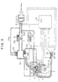
- the in-cylinder injection internal combustion engine equipped with the exhaust gas heating system is constructed as shown in FIG. 3, that is, is an internal combustion engine performing individual strokes of intake, compression, expansion and exhaust in a working cycle, namely, a four-cycle engine, is of the spark ignition type and moreover, is constructed as an in-cylinder injection internal combustion engine in which fuel is injected directly into a combustion chamber.
- an intake passage 2 and an exhaust passage 3 are connected to the combustion chamber designated at numeral 1 so that the intake passage 2 and the exhaust passage 3 can be communicated to the combustion chamber 1.
- the intake passage 2 and the combustion chamber 1 are brought into mutual communication under control by an intake valve 4, while the exhaust passage 3 and the combustion chamber 1 are brought into mutual communication under control by an exhaust valve 5.
- the intake passage 2 is provided with an air cleaner 6 and a throttle valve 7, which are arranged in this order from an upstream side.
- the exhaust passage 3, is provided with an exhaust gas purification catalytic converter 9, as an exhaust gas purification device, and an unillustrated muffler (silencer), which are arranged in this order from an upstream side of the exhaust passage 3.
- the intake passage 2 is also provided with a surge tank 2a.
- an exhaust gas recirculation system (hereinafter called the "ERG system") 10. Described specifically, an exhaust gas recirculation passage 10b is arranged so that the intake passage 2 is connected at the surge tank 2a with an upstream side of the exhaust passage 3. This exhaust gas recirculation passage 10b is provided with an EGR valve 10a.
- the flow rate of exhaust gas (which may also be called “emission” or “emission gas”) from the exhaust passage 3 to the intake passage 2 can be controlled.
- control of the EGR valve 10a is performed depending on operation conditions of the engine.
- the throttle valve 7 varies in opening depending on a stroke of an unillustrated accelerator pedal, whereby the quantity of air to be introduced into the combustion chamber 1 is adjusted.
- an idle speed control valve ISC valve
- ISC valve idle speed control valve
- Numeral 50 indicates an air bypass valve (ABV), which is arranged in a bypass line 50A communicating the intake passage 2 on an upper side of the throttle valve 7 with the surge tank 2a so that the throttle-valve-arranged portion of the intake passage 2 is bypassed.
- the air bypass valve 50 can adjust the air/fuel ratio by adjusting the quantity of intake air independently of the throttle valve 7.
- An injector (fuel injection valve) 8 as a fuel injection device is arranged with its opening facing on the combustion chamber 1 so that fuel is injected directly into the combustion chamber 1 in a cylinder. Needless to say, one injector 8 is arranged per cylinder. Assuming, for example, that the engine in this embodiment is an in-series 4-cylinder engine, four injectors 8 are arranged.
- air which has been inducted through the air cleaner 6 in an amount corresponding to an opening of the throttle valve 7 is inducted into the combustion chamber 1 when the intake valve 4 is opened.
- the thus-inducted air is mixed with fuel directly injected from the injector 8, and the resultant air-fuel mixture is ignited there at an appropriate timing by a spark plug 35.
- the air-fuel mixture is hence caused to burn so that an engine torque is produced.
- the thus-burnt air-fuel mixture is discharged as exhaust gas from the combustion chamber 1 into the exhaust passage 3.
- the exhaust gas After three noxious components of CO, HC and NOx in the exhaust gas are purified at the catalytic converter (which may hereinafter be called simply the "catalyst") as the exhaust gas purification device, the exhaust gas is deaden in noise and is then released to a side of the atmosphere.
- the catalytic converter which may hereinafter be called simply the "catalyst"
- this engine is an engine which can perform a fuel-saving operation while keeping the air/fuel ratio lean, and during a lean operation, NOx in exhaust gas cannot be fully purified if a conventional three-way catalyst is solely relied upon.
- the catalyst 9 is composed in combination of a lean NOx catalyst 9A and a three-way catalyst 9B.
- the arrangement of the three-way catalyst 9B on the downstream side of the lean NOx catalyst 9A is to ensure purification of CO and HC, which the lean NOx catalyst has failed to fully purify, while avoiding any interference with the purification of NOx at the lean NOx catalyst 9A.
- the three-way catalyst 9B can be omitted when the lean NOx catalyst 9A is equipped with a three-way function.
- the engine is constructed so that an inducted air flow, which has flowed into the combustion chamber 1 from the intake passage 2, forms a vertical swirl (reverse tumble flow).
- an inducted air flow which has flowed into the combustion chamber 1 from the intake passage 2 forms a vertical swirl (reverse tumble flow).
- the inducted air flow forms such a vertical swirl within the combustion chamber 1
- use of this vertical swirl makes it possible to have fuel gathered only in a vicinity of the spark plug 35 arranged, for example, centrally in a top part of the combustion chamber 1 and also to establish a state of an extremely lean air-fuel ratio in a part remote from the spark plug 35.
- the fuel consumption can be reduced while realizing stabilized stratified combustion.
- an air flow sensor 11 for detecting the quantity of inducted air from Karman vortex information
- an inducted air temperature sensor 12 for detecting the temperature of inducted air
- an atmospheric pressure sensor 13 for detecting an atmospheric pressure, all at an air-cleaner-arranged portion
- a throttle opening sensor 14 of the potentiometer type for detecting an opening of the throttle valve 7 and an idling switch 15 for detecting an idling state or the like, both at the throttle-valve-arranged portion.
- an oxygen concentration sensor 17 for detecting an oxygen concentration (O 2 concentration) in exhaust gas
- a catalyst temperature sensor (high temperature sensor) 26 for detecting the temperature of the catalyst or its vicinity as a purification device temperature computing unit.
- Other sensors include a coolant temperature sensor (coolant temperature detection unit) 19 as an engine temperature detection unit for detecting the temperature of an engine coolant (engine temperature); and as is shown in FIG. 2, a crank angle sensor 21 for detecting a crank angle (this crank angle sensor 21 also serves as a rotational speed sensor for detecting an engine speed) and a TDC sensor (cylinder-identifying sensor) 22 for detecting top dead center of a first cylinder (reference cylinder), both arranged in a vicinity of a cam.
- a coolant temperature sensor coolant temperature detection unit
- engine temperature detection unit for detecting the temperature of an engine coolant (engine temperature)
- a crank angle sensor 21 for detecting a crank angle
- this crank angle sensor 21 also serves as a rotational speed sensor for detecting an engine speed
- TDC sensor cylinder-identifying sensor 22 for detecting top dead center of a first cylinder (reference cylinder), both arranged in a vicinity of a cam.
- Detection signals from these sensors are inputted to an electronic control unit (ECU) 23.
- ECU electronice control unit
- the hardware construction of the ECU 23 can be illustrated as shown in FIG. 2.
- This ECU 23 is provided with a CPU 27 as its principal unit.
- detection signals are inputted through an input interface 28 and an analog/digital converter 30 from the inducted air temperature sensor 12, the atmospheric pressure sensor 13, the throttle opening sensor 14, the O 2 sensor 17, the coolant temperature sensor 19, the accelerator position sensor 24, the catalyst temperature sensor 26 and the battery sensor 25; and detection signals are also inputted through an input interface 29 from the air flow sensor 11, the crank angle sensor 21, the TDC sensor 22, the idling switch 15, the cranking switch 20 and an ignition switch and the like.
- the CPU 27 also exchange data with an ROM 31 that stores program data and fixed value data, an RAM 32 that is successively rewritten by updating, a free running counter 48, and a battery backed-up RAM (not shown) that is backed up by a battery to hold stored information, data and the like as long as the battery is connected.
- an ROM 31 that stores program data and fixed value data
- an RAM 32 that is successively rewritten by updating
- a free running counter 48 a free running counter 48
- a battery backed-up RAM (not shown) that is backed up by a battery to hold stored information, data and the like as long as the battery is connected.
- the data of the RAM 32 are erased and reset whenever an ignition switch is turned off.
- fuel injection control signals obtained as a result of computation at the CPU 27 are outputted to solenoids (injector solenoids) 8a of injectors 8 via solenoid drivers (four solenoid drivers in this embodiment; fuel injection valve drive unit) 34 for the respective cylinders.
- fuel injection control signals computed at the CPU 27 are outputted via the respective drivers 34 so that the injectors, for example, the four injectors 8 are successively driven.
- the engine is provided, as fuel injection modes, with a latter-stage injection mode that performs an injection of fuel in a compression stroke (especially, in a latter half of a compression stroke) to improve the gas mileage by achieving a lean operation based on stratified combustion, a former-stage injection mode that performs an injection of fuel in an intake stroke (especially, in a former half of an intake stroke) to achieve a lean operation based on premixed combustion and hence to obtain an output by a gentle acceleration, and a stoichiometric mode that performs an injection of fuel in an intake stroke to achieve a stoichiometric operation (theoretical air/fuel ratio operation) by premixed combustion and thus to improve the power output over the former-stage injection mode.
- a latter-stage injection mode that performs an injection of fuel in a compression stroke (especially, in a latter half of a compression stroke) to improve the gas mileage by achieving a lean operation based on stratified combustion
- a former-stage injection mode that performs
- the internal combustion engine is designed to inject additional fuel in an expansion stroke in addition to a fuel injection (primary fuel injection) for conventional combustion such as that described above.
- This additional fuel injection is to heat and activate the catalyst 9 by subjecting the additional fuel to combustion by a flame propagated from the primary combustion without energizing the spark plug again and then feeding the thus-heated exhaust gas to the catalyst 9.
- This additional fuel injection is therefore designed to perform control on a basis of operation conditions of the internal combustion engine, especially, the state of activation of the catalyst 9, so that as is illustrated in FIG. 4, an injection of additional fuel is conducted in each expansion stroke (specifically, while a flame still exists in each expansion stroke) of each cylinder and is ended when the catalyst 9 is brought back into an active state.
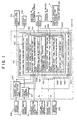
- the ECU 23 is provided with a fuel injection control unit 101 for performing the selection of one of the injection mode and the setting of a fuel injection quantity as shown in the functional block diagram of FIG. 1. Further, the ECU 23 is internally provided with an exhaust gas recirculation rate control unit 104 and an ignition timing control unit 107.
- the fuel injection control unit 101 is provided with a function for performing an injection of additional fuel when the catalyst 9 is inactive (additional fuel injection control unit) 102 and a function for performing fuel injection control at the time of a normal operation (conventional fuel injection control unit) 103.
- the additional fuel injection control unit 102 is a characteristic constitutional element of the exhaust gas heating system which is concerned with purification of exhaust gas.
- the additional fuel injection control unit 102 determines whether or not the catalyst 9 is in an active state. If the catalyst 9 is not found to be in an active state, an injection of additional fuel is performed during a flame lasting duration in which a flame of primary combustion based on the injection of the primary fuel still remains. Described specifically, when the temperature (hereinafter called the "catalyst temperature") ⁇ c.c of the catalyst 9 or its vicinity as detected by the catalyst temperature sensor 26 is determined or estimated to be equal to or lower than a predetermined temperature ⁇ o , the catalyst 9 is determined to be in an inactive state. Based on this determination, control is performed so that additional fuel is injected in an expansion stroke of each cylinder (see FIG. 4).
- the predetermined temperature ⁇ o means a target catalyst activation temperature and is determined based on a lower limit temperature for catalyst activation. For example, it may be set as a value which is obtained by adding a certain predetermined temperature to the lower limit temperature for catalyst activation. This lower limit temperature for catalyst activation is approximately 400° or so for the lean NOx catalyst employed in this embodiment.
- the target temperature ⁇ o as the predetermined temperature (the predetermined temperature will hereinafter be called the "target temperature") may be set to conform with a catalyst activation temperature.
- the additional fuel injection control unit 102 is provided with an injection quantity computing unit 112 for determining an injection quantity of additional fuel on the basis of a quantity of oxygen still remaining after primary combustion and also with an injection timing setting unit 110 for setting the timing of an injection of the additional fuel.
- the injection quantity computing unit 112 directly or indirectly detects the quantity of the oxygen still remaining after the primary combustion and then determines the injection quantity of the additional fuel on the basis of the quantity of the remaining oxygen so detected.
- the injection timing setting unit 110 sets an injecting duration and injection start time of additional fuel on the basis of various parameters affecting a flame lasting duration during which a flame of primary combustion remains, and is provided with a function (injecting duration setting unit) 114 for setting an injecting duration of additional fuel in each cycle in accordance with the injection quantity determined by the injection quantity computing unit 112 and also with a function (injection start time setting unit) 116 for setting an injection start time T INJ for the additional fuel.
- a function (injecting duration setting unit) 114 for setting an injecting duration of additional fuel in each cycle in accordance with the injection quantity determined by the injection quantity computing unit 112 and also with a function (injection start time setting unit) 116 for setting an injection start time T INJ for the additional fuel.
- the injection start time setting unit 116 sets an injection start time T INJ so that in an expansion stroke of each cylinder, an injection of additional fuel is performed in a combustion duration at the time of combustion by a conventional fuel injection (hereinafter called the "primary combustion"), in other words, in a duration in which a flame exists (hereinafter called the “flame lasting duration").
- the primary combustion a conventional fuel injection
- the flame lasting duration a duration in which a flame exists
- the setting of the injection start time T INJ of the additional fuel as described above is to cause combustion (hereinafter called the "additional combustion") of the fuel, which is injected by the additional fuel injection, without arrangement of any additional device, because it is necessary to perform the additional fuel injection in the flame lasting duration of fuel by a conventional fuel injection as is illustrated in FIG. 9.
- gasoline which is used as fuel has low self-ignition property, and hence has a property that it cannot undergo sure combustion unless a combustible source or an external energy source for inducing chemical decomposition of gasoline itself to cause combustion of gasoline is present.
- fuels having high self-ignition property include those having high setane numbers such as diesel oil.
- FIG. 9 diagrammatically illustrates internal cylinder pressures and heat release rates from a compression stroke to a combustion and expansion stroke.
- a thin curve A indicates heat release rates when only conventional fuel injections were performed
- a thick curve B designates heat release rates when additional fuel injections were performed
- a broken curve C represents internal cylinder pressures when only conventional fuel injections were performed
- a thick curve D shows internal cylinder pressures when additional fuel injections were performed.
- the durations indicated as heat release rates by the thin curve A and the thick curve B are equivalent to flame lasting durations.
- the thick curve D indicates that the internal cylinder pressure rises when an additional fuel injection is performed.
- the thermal energy obtained by the additional combustion is considered to be used in a greater proportion for the work that depresses the piston (gas expansion work). Such a rise in internal cylinder pressure is therefore not preferred for heating exhaust gas.
- the injection start time T INJ of additional fuel is set at a time as late as possible within an expansion stroke.
- the injection start time T INJ of the additional fuel must fall within the flame lasting duration as mentioned above. It is therefore desired to set the injection start time T INJ of the additional fuel at a time as late as possible within the flame lasting duration (i.e., at a time close to a flame dying time).
- a flame dying time which is an ending time of a flame lasting duration, varies under influence of various parameters such as the coolant temperature (engine temperature) ⁇ w, the exhaust gas recirculation rate at the time of primary combustion (EGR rate), the air/fuel ratio (A/F) at the time of primary combustion and the ignition timing T IG at the time of primary combustion. It is therefore necessary to take influence of these parameters into consideration upon setting an injection start time T INJ for additional fuel.
- a low coolant temperature ⁇ w leads to a deterioration in combustion and hence to an advance in flame dying time.
- T INJ injection start time
- a cylinder block and its peripheral components are cool when an engine is cool. Accordingly, heat tends to dissipate through the cylinder block and the like.
- a flame is brought into contact with an inner wall of the cylinder block over a wide area so that a large quenching zone is formed. Even if a flame of primary combustion begins to propagate, the flame therefore dies before it spreads throughout the combustion chamber.
- the flame lasting duration that is, the flame dying time varies when the ignition timing T IG is advanced or regarded. It is therefore preferred to set the injection start time T INJ of additional fuel in accordance with an advance or retard in the ignition timing T IG . Because, when the ignition timing T IG is advanced, the combustion duration becomes shorter and the flame dying time becomes earlier. When the ignition timing T IG is conversely retarded, the combustion becomes slow (the combustion velocity becomes slow) so that the flame dying time becomes later.
- the setting of the injection start time T INJ in an expansion stroke by the injection start time setting unit 116 is therefore conducted by correcting the basic fuel injection start time Tb INJ , which serves as a basis in the injection of additional fuel in the expansion stroke, with various correction factors in view of parameters affecting the flame lasting duration in which the flame of the primary combustion remains, that is, the coolant temperature ⁇ w, the primary-combustion-time EGR rate, the primary-combustion-time air/fuel ratio, and the flame dying time corresponding to the ignition timing T IG of the primary combustion.
- the injection start time setting unit 116 is therefore provided with a function (basic injection start time setting unit) 116A for setting a basic fuel injection start time and a function (flame dying time computing unit) 116B for setting an injection start time correction factor in view of a flame dying time which varies under the influence of various parameters.
- the injection start time setting unit 116 corrects the basic injection start time, which has been set by the basic injection start time setting unit 116A, by the injection start time correction factor set by the flame dying time computing unit 116B, whereby the injection start time T INJ for the additional fuel is set to inject the additional fuel at a timing where the additional fuel can be ignited by the flame of the primary combustion.
- the flame dying time computing unit 116B determines an injection start time correction factor, which is set while taking into consideration a flame dying time, i.e., an ending time of a flame lasting duration, on the basis of parameters affecting the flame lasting duration. Taking into consideration a flame dying time corresponding to various parameters such as a coolant temperature ⁇ w, an ERG rate, an air/fuel ratio (A/F), a primary-combustion-time ignition timing T IG and the like, an injection start time correction factor corresponding to the various parameters is determined from plural maps which indicate preset injection start time correction factors.
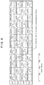
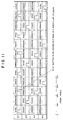
- FIGS. 6(A) through 6(D) show maps, which indicate injection start time correction factors corresponding to various parameters, respectively.
- FIG. 6(A) illustrates a first injection start time correction map (6A), which indicates a coolant temperature correction factor (first injection start time correction factor) K ⁇ .
- This coolant temperature correction factor K ⁇ has taken into consideration the flame dying time which becomes earlier as the coolant temperature ⁇ w drops. Since the flame dying time becomes earlier as the coolant temperature ⁇ w detected by the coolant temperature sensor 19 drops, this first injection start time correction factor K ⁇ is set at a smaller value as the coolant temperature ⁇ w drops, so that the injection start time T INJ is be advanced as the coolant temperature ⁇ w drops.
- FIG. 6(B) depicts a second injection start time correction map (6B), which indicates an exhaust gas recirculation rate correction factor (second injection start time correction factor) K E .
- the exhaust gas recirculation rate correction factor K E has taken into consideration the flame dying time which becomes later as the exhaust gas recirculation rate at the time of primary combustion decreases.
- the state of combustion varies and the flame dying time also varies.
- the second injection start time correction factor K E is therefore set so that the injection start time T INJ varies to remain conforming with the thus-varied flame dying time.
- FIG. 6(C) shows a third injection start time correction map (6C), which indicates an air/fuel ratio correction factor (third injection start time correction factor) K F .
- This air/fuel ratio correction factor K F has taken into consideration the flame dying time which delays as the main-combustion-time air/fuel ratio (A/F) becomes leaner. Since the flame dying time becomes later as the main-combustion-time air/fuel ratio set by the conventional fuel injection control unit 103 becomes leaner, the third injection start time correction factor K F is set at a greater value as the main-combustion-time air/fuel ratio becomes leaner, so that the injection start time T INJ is delayed as the main-combustion-time air/fuel ratio becomes leaner.
- FIG. 6(D) presents a fourth injection start time correction map (6D), which indicates an ignition timing correction factor (fourth injection start time correction factor) K I .
- This ignition timing correction factor K I has taken into consideration the flame dying time which corresponds to the main-combustion-time ignition timing T IG . Since the flame dying time delays as the main-combustion-time ignition timing set by the ignition timing control unit 107 is retarded, the fourth injection start time correction factor K I is set at a greater value as the main-combustion-time ignition timing is retarded, so that the injection start time T IG is delayed as the main-combustion-time ignition timing is retarded.
- the injection start time setting unit 116 determines an injection start time T INJ for additional fuel by adding a coolant correction factor K ⁇ , which has been obtained from the map (6A) of FIG. 6(A) stored in the flame dying time computing unit 116B on the basis of a coolant temperature ⁇ w detected by the coolant temperature sensor 19, to a basic fuel injection start time Tb INJ determined by the basic injection start time setting unit 116A (Tb INJ + K ⁇ ).
- an exhaust gas recirculation rate correction factor K E is obtained from the map (6B) of FIG. 6(B) stored in the flame dying time computing unit 116B on the basis of a main-combustion-time exhaust gas recirculation rate set by the exhaust gas recirculation rate control unit 104.
- This correction amount is then added to a basic fuel injection start time Tb INJ determined by the basic injection start time setting unit 116A (Tb INJ + K E ), whereby an injection start time T INJ for additional fuel is obtained.
- an air/fuel ratio factor K F is obtained from the map (6C) of FIG. 6(C) stored in the flame dying time computing unit 116B on the basis of a main-combustion-time air/fuel ratio set by the conventional combustion injection control unit 103.
- This correction amount is then added to a basic fuel injection start time Tb INJ determined by the basic injection start time setting unit 116A (Tb INJ + K F ), whereby an injection start time T INJ for additional fuel is determined.
- An injection duration (injection duration in a single working cycle) t ex for the additional fuel at this time is set at the injection duration setting unit 114.
- This injection duration setting unit 114 sets an injector driving duration t PLUS (which is equivalent to the injection duration) so that the additional fuel is injected in a fuel quantity M fuel corresponding to surplus oxygen still remaining in the cylinder after the primary combustion.
- the setting of the injector driving duration t PLUS in an expansion stroke by the injection duration setting unit 114 is performed as will be described hereinafter.
- the setting of the injector driving duration t PLUS in the expansion stroke by the injection duration setting unit 114 is performed by correcting a basic driving duration t B , which is equivalent to a basic injection duration and serves as a basis in the injection of the additional fuel in the expansion stroke, in accordance with an injection start time T INJ and a catalyst temperature ⁇ c.c.
- the injection duration setting unit 114 is therefore provided with a function (first injection duration correcting unit) 118 for determining the basic driving duration t B , which serves as a basis in the injection of the additional fuel in the expansion stroke, and correcting the basic driving duration t B by the catalyst temperature ⁇ c.c and also with a function (second injection duration correcting unit) 120 for correcting the basic driving duration t B by the injection start time T INJ in the expansion stroke.
- first injection duration correcting unit for determining the basic driving duration t B , which serves as a basis in the injection of the additional fuel in the expansion stroke, and correcting the basic driving duration t B by the catalyst temperature ⁇ c.c
- second injection duration correcting unit 120 for correcting the basic driving duration t B by the injection start time T INJ in the expansion stroke.
- the injection duration setting unit 114 calculates the basic driving duration t B on the basis of a fuel quantity M fuel which can be injected for the surplus oxygen in the cylinder after the primary combustion. Specifically, the injection duration setting unit 114 determines the quantity of oxygen, which still remains in the cylinder after the primary combustion, from an inducted air quantity Q per cylinder and per cycle as determined by the below-described conventional fuel injection control unit 103 and a target air/fuel ratio (target A/F), and then calculates the fuel quantity M fuel on the basis of the quantity of oxygen.
- target A/F target air/fuel ratio
- the first injection duration correcting unit 118 corrects the basic injection duration t B in accordance with the catalyst temperature ⁇ c.c determined by the catalyst temperature sensor 26 as a catalyst temperature computing unit.
- the first injection duration correcting unit 118 is therefore provided with a correcting factor setting unit 118A for correcting the basic injection duration t B by a correction factor (first injection duration correcting factor) K 2 , which has been determined beforehand in accordance with the catalyst temperature ⁇ c.c, so that the injection quantity of additional fuel becomes smaller as the catalyst temperature ⁇ c.c rises.
- This correcting factor setting unit 118A is provided with a map (17B), which indicates the first injection duration correcting factor K 2 determined beforehand in accordance with the catalyst temperature ⁇ c.c.
- the first injection duration correcting factor K 2 shown in the map (17B) is set so that, as is illustrated in FIG. 17(B), the injection quantity of additional fuel becomes smaller as the catalyst temperature ⁇ c.c rises.
- the first injection duration correcting factor K 2 is set at 1 to avoid correction of the basic driving duration t B when the catalyst temperature ⁇ c.c is low, and is set to gradually decrease to 0 when the catalyst temperature ⁇ c.c rises and approaches the target temperature ⁇ o.
- This setting is to promote the activation of the catalyst 9 by injecting additional fuel in a greater quantity as the catalyst temperature ⁇ c.c becomes lower because the catalyst 9 requires more activation as the catalyst temperature ⁇ c.c becomes lower; and in contrast, to decrease the injection quantity of additional fuel to avoid an injection of unnecessary fuel as the catalyst temperature ⁇ c.c becomes higher because the catalyst 9 requires less activation as the catalyst temperature ⁇ c.c becomes higher.
- the correction by the catalyst temperature ⁇ c.c at the injection duration correcting unit 118A is performed by obtaining the correction factor K 2 from the map (17B) on the basis of the catalyst temperature ⁇ c.c and then multiplying the basic driving duration t B with the correction factor K 2 (t B x K 2 ).
- the second injection duration correcting unit 120 is to correct the basic injection duration t B in accordance with the injection start time T INJ in the expansion stroke so that the injection quantity determined by the injection quantity computing unit 112 conforms with an actual injection quantity.
- This second injection duration correcting unit 120 is provided with a map (17A), which indicates a correction factor (second injection duration correcting factor) K 1 determined beforehand in accordance with the injection start time T INJ .
- the second injection duration correcting factor K 1 is set so that, as is appreciated from FIG. 17(A), the injector driving duration t PLUS becomes longer as the injection start time T INJ becomes earlier. Namely, when the injection start time T INJ becomes earlier in an expansion stroke, the internal cylinder pressure increases so that the quantity of fuel injected from the injector (the quantity per unit time) tends to decrease.
- the second injection duration correcting factor K 1 is therefore set so that the injector driving duration t PLUS becomes longer as the internal cylinder pressure becomes higher.
- the correction by the injection start time T INJ at the second injection duration correction unit 120 is performed by obtaining the correction factor K 1 from the map (17A) on the basis of the injection start time T INJ and then multiplying the basic driving duration t B with the correction factor K 1 (t B x K 1 ).
- the additional fuel injection is performed in an expansion stroke independently from the conventional fuel injection as shown in FIG. 4.
- a target output torque T of the engine is set based on an engine speed (rotational speed) Ne and an accelerator pedal stroke ⁇ ACC detected from the engine speed sensor 21 and various sensors 106, and either a early injection mode or a late injection mode is selected as an injection mode in accordance with the engine speed Ne and the target output torque T.
- the late injection mode is selected in a range where the engine speed Ne is low and the target output torque T is also low, and the early injection mode (the stoichiometric mode or the lean mode) is selected unless either the engine speed Ne or the target output torque is low.
- a fuel injection quantity is set as a fuel injecting duration T AU , which is an injector-driving duration and will be called an "injector driving pulse width" in actual control.
- a basic driving duration t B is first calculated by the following formula on the basis of an engine load (inducted air quantity per stroke) Q/Ne and a target air/fuel ratio (A/F, hereinafter abbreviated as "A/F").
- t B (Q/Ne) x (1/AF) x ( ⁇ AIR / ⁇ FUEL ) x (1/G INJ )
- the engine load Q/Ne is the quantity of air inducted in a stroke, and is determined by dividing an inducted air quantity Q detected at the air flow sensor 11 with an engine speed Ne detected at the engine speed sensor (crank angle sensor) 21.
- ⁇ AIR represents an air density
- ⁇ FUEL means a fuel density
- G INJ stands for an injector gain
- f represents various fuel correction factors. These fuel correction factors f are set in accordance with an engine coolant temperature detected by the coolant sensor 19, an inducted air temperature detected by the inducted air temperature sensor 12, an atmospheric pressure detected by the atmospheric pressure sensor 13, and the like, respectively. Further, t D is an injector insensitive duration (dead time).
- the exhaust gas recirculation rate control unit 104 controls the EGR valve (on/off valve) 10a as an exhaust gas recirculation unit on the basis of detection information from various sensors 106. For this purpose, a signal from the exhaust gas recirculation rate control unit 104 is sent to the additional fuel injection control unit 102 of the fuel injection control unit 101.
- the exhaust gas recirculation range control unit 104 in this embodiment has another function that controls the EGR valve 10a to decrease the exhaust gas recirculation rate or to reduce it to zero when an injection of additional fuel is performed in a flame lasting duration of an expansion stroke to heat exhaust gas for the activation of the catalyst 9.
- a signal from the injection timing setting unit 110 of the additional fuel injection control unit 102 is sent to the exhaust gas recirculation rate control unit 104.
- the ignition timing control unit 107 controls an ignition timing T IG by the spark plug 35 as an ignition device 108 on the basis of detection information from the crank angle sensor 21. For this purpose, a signal from the ignition timing control unit 107 is sent to the additional fuel injection control unit 102 of the fuel injection control unit 101.
- the ignition timing control unit 107 in this embodiment has another function that retards the ignition timing T IG of primary combustion when an injection of additional fuel is performed in a flame lasting duration of an expansion stroke to heat exhaust gas for the activation of the catalyst 9.
- a signal from the injection timing setting unit 110 of the additional fuel injection control unit 102 is sent to the ignition timing control unit 107.
- the control of a conventional fuel injection is performed, for example, as illustrated in FIG. 5(A), and the control of an additional fuel injection (the expansion-stroke fuel injection control) is carried out, for example, as shown in FIG. 5(B).
- step A10 an engine load Q/Ne (namely, a quantity of air inducted in a stroke) is calculated from an inducted air quantity Q and an engine speed Ne which have been detected by the air flow sensor 11 and the speed sensor 21, respectively.
- step A20 a basic driving duration t B is then calculated based on the engine load Q/Ne as indicated by the above formula.
- step A30 the basic driving duration t B is subjected to multiplication by various fuel correction factors f and also to like processing to calculate a fuel injecting duration t AU .
- a conventional fuel injection is then performed (step A40).
- this expansion stroke fuel injection control is performed when the lean operation mode is selected under the early injection mode or the late injection mode.
- FIG. 5(B) shows the control to be performed when an expansion stroke fuel injection is conducted in the early injection mode.
- steps B10 and B20 are performed. Namely, a catalyst temperature ⁇ c.c is read in step B10. It is then determined in step B20 whether or not the catalyst temperature ⁇ c.c is not higher than a target temperature ⁇ o.
- the processings of steps B30 to B90 are performed to conduct the expansion stroke fuel injection control. If the catalyst temperature ⁇ c.c is higher than the target temperature ⁇ o, the routine returns without performing the expansion stroke fuel injection control.
- steps B30 to B60 are first performed to set an injection start time T INJ for an expansion stroke.
- a target load (target Pe), an engine speed Ne, a coolant temperature ⁇ w, an ignition timing T IG for primary combustion and an EGR rate are read in step B30.
- a basic injection start time Tb INJ for the expansion stroke is next read from the prestored map.
- the basic injection start time Tb INJ is corrected by the EGR rate, the coolant temperature ⁇ w and the ignition timing T IG of the primary combustion and, in step B60, the expansion-stroke injection start time T INJ is set.
- steps B70 to B90 are then performed to set an injector driving duration t PLUS for the expansion stroke.
- an inducted air quantity Q per stroke and a target A/F are read in step B70.
- step B80 the quantity of oxygen still remaining in the cylinder after the primary combustion is determined from the inducted air quantity Q per cylinder and per cycle and based on the oxygen quantity, a fuel quantity M fuel is calculated.
- step B90 the basic driving duration t B for the injection of additional fuel in the expansion stroke is corrected by the injection start time T INJ and the catalyst temperature ⁇ c.c and based on this setting, the additional fuel injection is performed in the expansion stroke.
- the time until activation of the catalyst 9 can be shortened, leading to a further advantage that the contents of noxious components (HC, CO, NOx) in exhaust gas can be reduced.
- the injection start time T INJ of the additional fuel is set to fall within the flame lasting duration which varies in accordance with various parameters.
- the combustion of the additional fuel is therefore assured so that exhaust gas can be heated surely.
- the exhaust gas heating system of the first embodiment has the advantage that exhaust gas of a temperature high enough for the activation of the catalyst 9 can be obtained despite the arrangement of the catalyst 9 at the position remote from the engine.
- the first embodiment sets an injection start time T INJ at an optimal timing (for example, a timing close to a flame dying time) in accordance with various parameters while taking into consideration the flame dying time of a flame lasting duration.
- an optimal timing for example, a timing close to a flame dying time
- An injection start time setting unit 116 is provided with the basic injection start time setting unit 116A and the flame dying time computing unit 116B as in the above-described first embodiment.
- the injection start time setting unit 116 is also provided with a function (flame lasting duration adjusting unit) 116C for performing an adjustment in a flame lasting duration of primary combustion, that is, for performing an adjustment in a flame dying time as an ending time of the flame lasting duration.
- a function flame lasting duration adjusting unit 116C for performing an adjustment in a flame lasting duration of primary combustion, that is, for performing an adjustment in a flame dying time as an ending time of the flame lasting duration.
- the flame lasting duration adjusting unit 116C is provided with a control unit 116C1 for adjusting control amounts for the exhaust gas flow rate, air/fuel ratio and ignition timing as parameters affecting the flame lasting duration of primary combustion and also with a storage unit 116C2 for storing flame lasting durations corresponding to the control amounts for the individual parameters.
- the flame lasting duration adjusting unit 116C reads from the storage unit 116C2 control amounts associated with the individual parameters, said control amounts being required to set a flame lasting duration corresponding to a degree of the need for the activation of the catalyst 9, and then adjusts the individual parameters by the control unit 116C1 to achieve the control amounts so that the flame lasting duration is adjusted.
- the storage unit 116C2 is provided with plural maps which indicate the flame lasting durations corresponding to the control amounts associated with the exhaust gas flow rate, air/fuel ratio and ignition timing as the parameters affecting the flame lasting duration of primary combustion.
- FIG. 7(A) shows a first map (7A), which indicates flame lasting durations and flame dying times as ending times of the respective flame lasting durations.
- the flame lasting durations have been set beforehand to cope with changes in heat release rate. These changes in turn correspond to control amounts associated with the primary-combustion-time exhaust gas recirculation rate (EGR rate).
- the first map (7A) is set so that the flame lasting duration becomes longer with the exhaust gas recirculation rate.
- FIG. 7(B) depicts a second map (7B), which indicates flame lasting durations and flame dying times as ending times of the respective flame lasting durations.
- the flame lasting durations have been set beforehand to cope with changes in heat release rate. These changes in turn correspond to control amounts associated with the primary-combustion-time air/fuel ratio (A/F).
- the second map (7B) is set so that the flame lasting duration becomes longer as the air/fuel ratio becomes leaner.
- FIG. 7(C) shows a third map (7C), which indicates flame lasting durations and flame dying times as ending times of the respective flame lasting durations.
- the flame lasting durations have been set beforehand to cope with changes in heat release rate. These changes in turn correspond to control amounts associated with the primary-combustion-time ignition timing T IG .
- the third map (7C) is set so that the flame lasting duration becomes longer as the retard in the ignition timing becomes greater.
- the section indicated by hatching indicates flame lasting durations.
- the intersecting points between a boundary line X and heat release rates, which correspond to control amounts associated with the corresponding parameter, indicate flame dying times corresponding to the control amounts associated with the same parameter.
- the flame lasting duration adjusting unit 116C reads, from the first map (7A) shown in FIG. 7(A), a control amount which is associated with the exhaust gas recirculation rate and serves to extend the flame lasting duration as the temperature determined by the catalyst temperature sensor 26 becomes lower.
- the flame lasting duration adjusting unit 116C then controls the exhaust gas recirculation rate control unit 104 by the control unit 116C1 so that the control amount is obtained.
- the flame lasting duration adjusting unit 116C reads, from the second map (7B) shown in FIG. 7(B), a control amount which is associated with the ignition timing and serves to extend the flame lasting duration as the temperature determined by the catalyst temperature sensor 26 becomes lower.
- the flame lasting duration adjusting unit 116C then controls the ignition timing control unit 107 by the control unit 116C1 so that the control amount is obtained.
- the flame lasting duration adjusting unit 116C reads, from the third map (7C) shown in FIG. 7(C), a control amount which is associated with the air/fuel ratio and serves to extend the flame lasting duration as the temperature determined by the catalyst temperature sensor 26 becomes lower.
- the flame lasting duration adjusting unit 116C then controls the conventional fuel injection control unit 103 by the control unit 116C1 so that the control amount is obtained.
- the injection start time T INJ of additional fuel is then set by the injection start time setting unit 116 so that the injection of the additional fuel is performed within the flame lasting duration adjusted by the flame lasting duration adjusting unit 116C.
- the exhaust gas recirculation rate control unit 104 is controlled by the flame lasting duration adjusting unit 116C so that the exhaust gas is recirculated only in a small proportion (about 20% or so at the maximum) to adjust, i.e., extend the flame lasting duration of primary combustion.
- the injection start time T INJ of additional fuel is set by the injection start time setting unit 116 so that the additional fuel is injected within the flame lasting duration adjusted by the flame lasting duration adjusting unit 116.
- such control of an exhaust as recirculation rate is performed when the catalyst temperature ⁇ c.c is somewhat lower than the activation temperature.
- the above-described control can reduce the heat release rate of thermal energy, which has been obtained by the additional combustion, to an expansion stroke so that the temperature of exhaust gas can be made higher although the injection quantity of the additional fuel is the same. This makes it possible to more efficiently heat exhaust gas, thereby bringing about an advantage that the catalyst temperature ⁇ c.c can be promptly brought to the target temperature ⁇ o.
- the efficiency of purification of exhaust gas can be increased by recirculating the exhaust gas.
- the exhaust gas recirculation rate is set at 0 by the exhaust gas recirculation rate control unit 104 to retain remaining oxygen in a quantity sufficient for the combustion of additional fuel without performing the control by the control unit 116C1 of the flame lasting duration adjusting unit 116C.
- the ignition timing control unit 107 is controlled by the flame lasting duration adjusting unit 116C to retard the ignition timing T IG so that the flame dying time of the primary combustion is delayed, and moreover, the ignition start time T INJ for the additional fuel is set by the injection start time setting unit 116 so that the additional fuel is injected during the flame lasting duration adjusted by the flame lasting duration adjusting unit 116C.
- the thermal energy obtained by the additional combustion is used in a smaller proportion for the expansion of gas in the expansion stroke so that, although the additional fuel is injected in the same quantity, the exhaust gas can be more efficiently heated to a higher temperature.
- thermal energy available from additional combustion can also be effectively used to obtain exhaust gas of a high temperature by adjusting the air/fuel ratio of primary combustion to a leaner side on the basis of the above-mentioned map (7B) of FIG. 7(B) to such an extent that the maximum pressure within the combustion chamber and the crank angle corresponding to the maximum pressure do not vary.
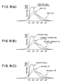
- FIGS. 8(A), 8(B) and 8(C) diagrammatically illustrate variations in heat release rate corresponding to individual control amounts when additional fuel was injected by adjusting the exhaust gas recirculation rate, the air/fuel ratio of primary fuel and the ignition timing of the primary fuel through the flame lasting duration adjusting unit 116C so that the flame dying time is delayed, in other words, the flame lasting duration is extended.
- the solid curves indicate conventional cases where the exhaust gas recirculation rate, the air/fuel ratio of the primary fuel and the ignition timing of the primary fuel as the parameters for heating the exhaust gas were not changed.
- the injection start time is set by the injection start time setting unit 116 so that, as described above, additional fuel is injected during a flame lasting duration in which a flame of primary combustion based on an injection of primary fuel in an expansion stroke remains; and, when the engine is brought into such an operation state that the catalyst temperature ⁇ c.c is expected to drop to a temperature lower than a target temperature ⁇ o (for example, an idling operation state or a decelerated operation state) after the catalyst 9 has reached the target temperature ⁇ o or close to the target temperature ⁇ o, the injection start time is set by the injection start time setting unit 116 to perform an additional fuel injection at a timing later than the additional fuel injection timing for the low-temperature start-up, that is, after the flame lasting duration (for example, at the end of the expansion stroke or in an exhaust stroke), whereby the fuel still remaining in the unburnt form in the exhaust gas is caused to burn
- the additional fuel is not injected in an expansion stroke but is injected after the expansion stroke. This makes it possible to reduce the possibility that the heat available from the additional combustion may be used for gas-expanding work, thereby bringing about the advantage that the exhaust can be efficiently heated.
- the exhaust gas is subjected to re-combustion in the expansion stroke so that the temperature of the exhaust gas is significantly raised to efficiently activate the catalyst.
- the engine may be brought into an idling operation state or a decelerated operation state which has the potential problem that the catalyst temperature may drop. In this case, the fuel which still remains in the unburnt form in the exhaust gas is caused to burn by the catalyst 9. This has brought about the advantage that the catalyst 9 can be efficiently activated.
- the injection timing of the additional fuel was changed to the specific timing (flame lasting duration) in the expansion stroke or to the timing later than the specific timing depending on whether the additional fuel injected at the time of a start-up or in an operation state other than such a start-up.
- a basis for such a change in the injection timing is however not limited to such a change in the operation state.
- a detection unit is arranged to detect or estimate whether or not a catalyst temperature ⁇ c.c determined by the catalyst temperature sensor 26 is not lower than a lowest temperature (preset temperature) at which the additional fuel, namely, the fuel still remaining in the unburnt form in exhaust gas can burn within the catalyst (exhaust gas purification device). Based on an output from the detection unit, an injection start time is set by the injection start time setting unit 116.
- an injection start time is set by the injection start time setting unit 116 so that the additional fuel is injected after the flame lasting duration (for example, at the end of the expansion stroke or in the exhaust stroke).
- the fuel i.e., the additional fuel
- the unburnt hydrocarbons therefore begin to burn inside the catalyst without being used for the gas-expanding work, so that the heating of the catalyst can be efficiently performed.
- An injection start time is therefore set by the injection start time unit 116 so that the injection of the additional fuel is performed within the flame lasting duration in which a flame still remains (for example, in an expansion stroke).
- the above-mentioned lowest temperature is lower than the target temperature ⁇ o which corresponds to a temperature required for bringing the catalyst into an activated state.
- the exhaust gas can be heated more efficiently if the fuel injection quantity, that is, the fuel injecting duration (hence, the injector driving duration) is set by the injecting duration setting unit 102 in accordance with the above-described respective parameters.
- the exhaust gas heating system of the second embodiment for the in-cylinder injection internal combustion engine is different from that of the first embodiment in that the additional fuel injection control unit 102 is equipped with a different injecting duration setting unit 114.
- the injecting duration setting unit 114 in this embodiment is provided with a cylinder designating unit 118B as shown in FIG. 10, so that the cylinder designating unit 118B specifies one or more particular cylinders to inject additional fuel thereinto with a view to adjusting the quantity of fuel in injecting additional fuel.
- the cylinder designating unit 118B designates one or more cylinders for the injection of additional fuel. Namely, when the catalyst temperature ⁇ c.c is substantially lower than the target temperature ⁇ o, it is considered to perform the additional fuel injection in all cylinders. In this case, the cylinder designating unit 118B designates all the cylinders for the injection of additional fuel.
- the cylinder designating unit 118B designates only such one or some of the cylinders for the injection of additional fuel.
- one or some of the cylinders for the injection of additional fuel one or some particular cylinders may be chosen.
- a plurality of combustion cycles may be performed by choosing one or some cylinders for the injection of additional fuel per combustion cycle.
- the additional fuel injection may also be performed by selecting all the cylinders one after one in each combustion cycle, for example, by performing an additional fuel injection only in the first cylinder in a given combustion cycle, another additional fuel injection only in the third cylinder in the next combustion cycle, a further additional fuel injection only in the fourth cylinder in the subsequent combustion cycle, a still further additional fuel injection only in the second cylinder in the still further combustion cycle, and so on.
- the additional fuel injection may also be performed by choosing only some of the cylinders (for example, the first cylinder and the fourth cylinder) as needed, for example, by performing an additional fuel injection only in the first cylinder in a given combustion cycle, another additional fuel injection only in the fourth cylinder in the next combustion cycle, a further additional fuel injection only in the first cylinder in the subsequent combustion cycle, a still further additional fuel injection only in the fourth cylinder in the still further combustion cycle, and so on.
- the additional fuel injection may also be performed by choosing only some of the cylinders (for example, the first cylinder and the fourth cylinder) as needed, for example, by performing an additional fuel injection only in the first cylinder in a given combustion cycle, another additional fuel injection only in the fourth cylinder in the next combustion cycle, a further additional fuel injection only in the first cylinder in the subsequent combustion cycle, a still further additional fuel injection only in the fourth cylinder in the still further combustion cycle, and so on.
- the additional fuel injection when the additional fuel injection is performed only in two cylinders or three cycles per combustion cycle, the additional fuel injection can be performed by using only particular cylinders or employing all or some of the cylinders in an appropriate order.
- the cylinder designating unit 118B designates one or more particular cylinders in such a way that more cylinders are designated for the injection of the additional fuel as the catalyst temperature ⁇ c.c drops further from the target temperature ⁇ o and the additional fuel is injected into substantially all the cylinders when the catalyst temperature ⁇ c.c has become lower by at least a predetermined value than the target temperature ⁇ o.
- This setting of the expansion-stroke injector driving duration t PLUS is performed by correcting a basic driving duration t B , which serves as a basis for an injection of additional fuel in the expansion stroke, by an injection start time T INJ .
- the basic driving duration t B is calculated as in the above-described first embodiment, and the correction by the expansion-stroke injection start time T INJ is also performed in a similar manner as in the above-described first embodiment.
- the number of injection-performing cylinder(s) in each of which an additional fuel injection is to be performed in an expansion stroke (hereinafter referred to as the "injection-performing cylinder number") N INJ is set in accordance with a catalyst temperature ⁇ c.c.
- This adjustment of the injection-performing cylinder number therefore makes it possible to the fuel quantity in accordance with the catalyst temperature ⁇ c.c.
- the correction of the fuel quantity by the cylinder designating unit 118B in accordance with a catalyst temperature ⁇ c.c detected by the catalyst temperature sensor 26 is performed as illustrated in FIG. 17(C), namely, by determining an injection-performing cylinder number N INJ , in other words, either increasing or decreasing the injection-performing cylinder number N INJ in accordance with the catalyst temperature ⁇ c.c with reference to a cylinder number map (17C) preset corresponding to various catalyst temperatures ⁇ c.c.
- the cylinder number map (17C) is set to adjust the fuel quantity in such a way that the additional fuel injection is performed in all the cylinders when the catalyst temperature ⁇ c.c is low and the injection-performing cylinder number N INJ is decreased as the catalyst temperature ⁇ c.c rises and approaches the target temperature ⁇ o.
- FIG. 11 illustrates a case in which the expansion-stroke additional fuel injection is performed only in the first cylinder (#1) designated as a particular cylinder.
- control of conventional fuel injections is performed, for example, as in the first embodiment [see FIG. 5(A)] and moreover, control of additional fuel injections (expansion-stroke fuel injection control) is conducted, for example, as depicted in FIG. 12.
- the additional fuel injection control by this system is different only in step C90 from the additional fuel injection control by the system of the first embodiment.
- steps C10 to C80 correspond to steps B10 to B80, respectively, and perform similar processing. Their description is therefore omitted herein.
- an expansion-stroke injector driving duration t PLUS is set by correcting a basic driving duration t B , which serves as a basis for an additional fuel injection in an expansion stroke, in accordance with an injection start time T INJ .
- an injection-performing cylinder number N INJ is determined based on the catalyst temperature ⁇ c.c with reference to the cylinder number map (17C) preset as shown in FIG. 17(C).
- injection-performing cylinder number N INJ indicates the number of cylinder(s) in each which an additional fuel injection is performed while the crankshaft rotates over 720°. As is illustrated in FIG. 17(C), the additional fuel injection is performed in a plurality of cylinders (all the cylinders in this embodiment) when the catalyst temperature ⁇ c.c is low and, as the catalyst temperature ⁇ c.c rises, the injection-performing cylinder number is decreased further.
- the fuel injection can be performed as described above, namely, by using only particular one or more cylinders or by using the cylinders successively, one or more cylinders but not all the cylinders per combustion cycle, without limiting the injection-performing cylinder(s) to any particular cylinder(s).
- the fuel quantity of the additional injection can be set by adjusting the injection-performing cylinder number on the basis of the catalyst temperature ⁇ c.c. This has an advantage that the catalyst 9 can be heated without practically deteriorating the gas mileage.
- additional fuel can be injected in one or more particular cylinders or in particular cylinders, which have been designated to use all the cylinders in more than one combustion cycle, when the catalyst temperature ⁇ c.c is slightly lower than the target temperature ⁇ o.
- the catalyst temperature ⁇ c.c can be promptly raised to the target temperature ⁇ o.
- the exhaust gas heating system of the third embodiment for the in-cylinder injection internal combustion engine is constructed like the second embodiment as shown in FIG. 13, but is different from the system of the second embodiment in the functions of an injecting timing setting unit 110 and an injecting duration setting unit 114, which an additional fuel injection control unit 102 is equipped with.
- the exhaust gas heating system of this embodiment for the in-cylinder injection internal combustion engine is different in that additional fuel is injected twice in an expansion stroke.
- the ignition timing setting unit 110 is provided with a function to set injection start times of plural divided injections (divided injection start time setting unit) 122 so that an injection quantity of additional fuel determined by the injection quantity computing unit 112 is divided in plural portions (N portions), and the injecting duration setting unit 114 is provided with a function to set injecting durations of the plural divided injections.
- the injection quantity of the additional fuel is divided into two portions. Accordingly, the first divided injection is an (N-1) th divided injection, and the second divided injection is an N th divided injection.
- the divided injection start time setting unit 122 sets the first (N-1 th ) injection start time T1 INJ in and the second (N th ) injection start time T2 INJ in at least an expansion stroke.
- the first injection start time T1 INJ in the expansion stroke is calculated in a similar manner as the expansion-stroke injection start time T INJ in the first embodiment.
- the second injection start time T2 INJ in the expansion stroke is determined based on the expansion-stroke first injection start time T1 INJ , a coolant temperature ⁇ w, and a fuel quantity M fuel injectable to surplus oxygen in a cylinder. It is preferable to set the expansion-stroke second injection start time T2 INJ at a time immediately before an exhaust valve opens.
- thermal energy of the additional combustion can be used efficiently.
- the flame lasting duration is extended as indicated by a curve B.
- the flame lasting duration is extended as indicated by a phantom (long and two short dashes line) in the diagram so that the proportion of thermal energy used for the expanding work becomes smaller. As a consequence, the thermal energy obtained by the additional combustion can be used more effectively for heating exhaust gas.
- the injecting duration setting unit 114 is designed to set at least a first (N-1 th ) injector driving duration t1 PLUS at least in an expansion stroke and a second (N th ) injector driving duration t2 PLUS in the expansion stroke.
- the cylinder designating unit 118B which the injecting duration setting unit 114 is provided with designates an injection-performing cylinder number.
- This injecting duration setting unit 114 is also designed to set the expansion-stroke first injector driving duration t1 PLUS and the expansion-stroke second injector driving duration t2 PLUS so that the additional fuel is injected in a fuel quantity M fuel corresponding to surplus oxygen still remaining in the cylinder after the primary combustion.
- the setting of the expansion-stroke first injector driving duration t1 PLUS by the injecting duration setting unit 114 is conducted by correcting a basic driving duration t B , which serves as a basis for the additional fuel injections in the expansion stroke, in accordance with the expansion-stroke first injection start time T1 INJ and a coolant temperature ⁇ w.
- the expansion-stroke first injector driving duration t1 PLUS is set by correcting the basic driving duration t B to inject the fuel in such a quantity that the flame dying time can be delayed and can be brought toward an opening timing of an exhaust valve as close as possible.
- the fuel is injected in such a quantity that the flame dying time can be delayed to the opening timing of the exhaust valve.
- the expansion-stroke first injector driving duration t1 PLUS is set so that the fuel is injected in a quantity smaller than the injection quantity of the expansion-stroke second fuel injection. This makes it possible to have thermal energy, which has been obtained by the additional combustion, used in a smaller proportion for expanding gas in the expansion stroke and also to improve the gas mileage.
- the basic driving duration t B is calculated in a similar manner as in the above-described first and second embodiments, so that its description is omitted herein.
- the basic driving duration t B is calculated as the sum of the expansion-stroke first injector driving duration t1 PLUS and the expansion-stroke second injector driving duration t2 PLUS .
- the correction by the expansion-stroke first injection start time T1 INJ is performed in a similar manner as the correction by the injection start time T INJ in the above-described first and second embodiments. Its description is therefore omitted herein.
- the correction by the coolant temperature ⁇ w as the engine temperature is performed by determining an injection percentage factor (third injecting duration correction factor) K 3 based on the coolant temperature ⁇ w with reference to a map (17D), in which injection percentage factors are set relative to various coolant temperatures ⁇ w, as shown in FIG. 17(D) and then multiplying the basic driving duration t B with the injection percentage factor K 3 (t B x K 3 ).
- the map (17D) is set in such as way that, as is shown in FIG. 17(D), the expansion-stroke first injector driving duration t1 PLUS becomes shorter as the coolant temperature ⁇ w rises. Specifically, the map (17D) is set so that the percentage of the first injector driving duration t1 PLUS (namely, the N-1 th divided injection quantity) becomes greater than the second injector driving duration t2 PLUS (namely, the N th divided injection quantity) when the coolant temperature ⁇ w is low.
- the map (17D) is also set so that the percentage of the first injector driving duration t1 PLUS (namely, the N-1 th divided injection quantity) becomes smaller than that of the second injector driving duration t2 PLUS (namely, the N th divided injection quantity) as the coolant temperature ⁇ w rises.
- the setting of the expansion-stroke second injector driving duration t2 PLUS by the injecting duration setting unit 114 is performed by correcting the basic driving duration T B , which serves as the basis for the additional fuel injection in the expansion stroke, in accordance with the expansion-stroke second injection start time T2 INJ and the coolant temperature ⁇ w .
- the basic driving duration t B is calculated in a similar manner as in the above-described setting of the expansion-stroke first injector driving duration t1 PLUS .
- the correction by the expansion-stroke second injection start time T2 INJ is carried out in a similar manner as in the above-described setting of the expansion-stroke first injector driving duration t1 PLUS .
- the correction by the coolant temperature ⁇ w is performed as in the case of the above-described setting of the expansion-stroke first injector driving duration t1 PLUS , namely, by determining an injection ratio factor K 3 based on the coolant temperature ⁇ w with reference to the map (17D), in which injection percentage factors have been set beforehand relative to various coolant temperatures ⁇ w as shown in FIG. 17(D), and then multiplying the basic driving duration t B with (1-K 3 ) obtained from the injection percentage factor K 3 [t B x (1-K 3 )].
- the correction of the fuel quantity in accordance with the catalyst temperature ⁇ c.c is performed by adjusting the number of cylinder(s), in each of which an additional fuel injection is to be performed, by the cylinder designating unit 118B in a similar manner as in the above-described second embodiment. Described specifically, this correction is performed by determining, that is, either increasing or decreasing the injection-performing cylinder number N INJ on the basis of the catalyst temperature ⁇ c.c with reference to the preset map (17D) as shown in FIG. 17(D).
- FIG. 14 illustrates a case in which the expansion-stroke additional fuel injection is performed in all the cylinders.
- control of conventional fuel injections is performed, for example, as in the first and second embodiments [see FIG. 5(A)] and moreover, control of additional fuel injections (expansion-stroke fuel injection control) is conducted, for example, as depicted in FIG. 15.
- the additional fuel injection control by this system is different only in step D60 and step D90 from the additional fuel injection control by the system of the first embodiment.
- steps D10 to D50 correspond to steps B10 to B50 and steps D70 and D80 correspond to steps B70 and B80, respectively, and perform similar processing. Their description is therefore omitted herein.
- step D60 the expansion-stroke first injection start time T1 INJ is set by the divided injection start time setting unit 122.
- step D90 the expansion-stroke second injection start time T2 INJ is determined by the injection start time setting unit 102A on the basis of the expansion-stroke first injection start time T1 INJ , the coolant temperature ⁇ w, the fuel quantity M fuel injectable to the surplus oxygen in the cylinder.
- expansion-stroke first injector driving duration t1 PLUS and the expansion-stroke second injector driving duration t2 PLUS are determined by the injecting duration setting unit 114.
- the expansion-stroke first injector driving duration t1 PLUS is determined by correcting the basic driving duration t B in accordance with the expansion-stroke first injection start time T1 INJ and the coolant temperature ⁇ w
- the expansion-stroke second injector driving duration t2 PLUS is determined by correcting the basic driving duration t B in accordance with the expansion-stroke second injection start time T2 INJ and the coolant temperature ⁇ w.
- the injection-performing cylinder number N INJ is determined by the cylinder designating unit 118B which the injecting duration setting unit 114 is equipped with.
- the flame lasting duration can be extended by performing the first injection while the flame of the primary combustion still remains. This makes it possible to delay the second injection start time T2 INJ (preferably to the end of the expansion stroke), so that the thermal energy of the additional combustion can be effectively used. This has led to an advantage that the thermal energy of the additional combustion can heat the exhaust gas and can promptly bring the catalyst temperature ⁇ c.c to the target temperature ⁇ o.
- the additional fuel injection is performed twice.
- this is not limited to twice and can be performed plural times (N times)
- the additional fuel When the additional fuel is injected by dividing it into plural portions, it is not absolutely necessary to set the injection quantity of the first injection so that its flame remains until shortly before the exhaust valve opens. It is possible to set the injection quantity of a second or subsequent injection so that its flame dying time can be extended until shortly before the exhaust valve opens. Concerning the last (N th ) additional fuel injection, it is particularly preferred to set its timing at a timing immediately before the opening of the exhaust valve so that the last (N th ) additional fuel injection corresponds to the second additional fuel injection in the third embodiment. It is also preferred to set the injection quantity of the last additional fuel injection at a value as great as possible.
- the correction of the fuel quantity based on the catalyst temperature ⁇ c.c is performed by adjusting the number of cylinders for use in performing the additional fuel injection in the expansion stroke.
- the present invention is not limited to the above-described embodiments.
- the quantity of oxygen remaining at the time of primary combustion is determined from the quantity Q of air inducted per cylinder and the target A/F and upon conducting an expansion-stroke injection, the quantity of fuel to be injected through the fuel injection valve 8 is determined based on the oxygen quantity.
- this injection quantity can also be set as such a fixed injection quantity that the fuel so injected can undergo additional combustion.
- the catalyst temperature sensor 26 is arranged as a purification device temperature computing unit.
- the catalyst temperature ⁇ c.c is detected directly by the catalyst temperature sensor 26. Based on the detection result, it is determined whether or not the catalyst 9 requires heating (as a unit having this function, a catalyst heating determination unit is arranged). If the catalyst is determined to require heating, the expansion-stroke injection is then performed.
- the expansion-stroke injection can also be performed based on an output from a start-up engine temperature detection unit for detecting if the engine temperature (coolant temperature) at the time of a start-up is not higher than a preset temperature or from an elapsed time detection unit for detecting an elapse of a time period from a start-up (a variable or fixed, predetermined time period set depending on the coolant temperature or the like at the time of a start-up).
- the expansion-stroke injection can be always performed shortly after a start-up on the basis of an output from a start-up detection unit.
- the engine temperature detection unit, the elapsed time detection unit and the start-up detection unit correspond to the catalyst temperature sensor 26 as a purification device temperature computing unit in each of the above-described embodiments.
- the cylinder designating unit 118B is arranged.
- the number of cylinders for use in performing the expansion-stroke injection is varied (including use of all the cylinders) depending on the catalyst temperature ⁇ c.c.
Applications Claiming Priority (3)
| Application Number | Priority Date | Filing Date | Title |
|---|---|---|---|
| JP172661/96 | 1996-07-02 | ||
| JP17266196 | 1996-07-02 | ||
| JP17266196 | 1996-07-02 |
Publications (3)
| Publication Number | Publication Date |
|---|---|
| EP0826869A2 EP0826869A2 (en) | 1998-03-04 |
| EP0826869A3 EP0826869A3 (en) | 1999-10-27 |
| EP0826869B1 true EP0826869B1 (en) | 2002-10-09 |
Family
ID=15946038
Family Applications (1)
| Application Number | Title | Priority Date | Filing Date |
|---|---|---|---|
| EP97110823A Expired - Lifetime EP0826869B1 (en) | 1996-07-02 | 1997-07-01 | Exhaust gas heating system for in-cylinder injection internal combustion engine |
Country Status (5)
| Country | Link |
|---|---|
| US (1) | US6041591A (zh) |
| EP (1) | EP0826869B1 (zh) |
| KR (1) | KR100272024B1 (zh) |
| CN (1) | CN1077212C (zh) |
| DE (1) | DE69716205T2 (zh) |
Families Citing this family (77)
| Publication number | Priority date | Publication date | Assignee | Title |
|---|---|---|---|---|
| US6212880B1 (en) * | 1996-09-20 | 2001-04-10 | Hitachi, Ltd. | Engine control device |
| JP3521790B2 (ja) | 1998-03-25 | 2004-04-19 | 株式会社デンソー | 内燃機関の制御装置 |
| US6134884A (en) * | 1998-04-01 | 2000-10-24 | Toyota Jidosha Kabushiki Kaisha | Air-fuel ratio control apparatus for internal combustion engine |
| JP3584738B2 (ja) * | 1998-06-29 | 2004-11-04 | 日産自動車株式会社 | 筒内直噴式火花点火エンジン |
| US6269791B1 (en) | 1998-07-22 | 2001-08-07 | Toyota Jidosha Kabushiki Kaisha | Control system for an internal combustion engine |
| US6330796B1 (en) | 1998-08-03 | 2001-12-18 | Mazda Motor Corporation | Control device for direct injection engine |
| JP3325230B2 (ja) | 1998-08-03 | 2002-09-17 | マツダ株式会社 | 筒内噴射式エンジンの触媒暖機方法及び同装置 |
| US6651422B1 (en) * | 1998-08-24 | 2003-11-25 | Legare Joseph E. | Catalyst efficiency detection and heating method using cyclic fuel control |
| IT1304135B1 (it) | 1998-11-26 | 2001-03-07 | Magneti Marelli Spa | Metodo di controllo dell' iniezione e dell' accensione in un motoreendotermico ad iniezione diretta per accelerare il riscaldamento del |
| US6272850B1 (en) * | 1998-12-08 | 2001-08-14 | Ford Global Technologies, Inc. | Catalytic converter temperature control system and method |
| JP3454174B2 (ja) * | 1998-12-22 | 2003-10-06 | トヨタ自動車株式会社 | ハイブリッド車輌の排気浄化装置 |
| US6718756B1 (en) * | 1999-01-21 | 2004-04-13 | Mitsubishi Jidosha Kogyo Kabushiki Kaisha | Exhaust gas purifier for use in internal combustion engine |
| US6401454B2 (en) * | 1999-03-19 | 2002-06-11 | Hitachi, Ltd. | Engine control device |
| FR2791395B1 (fr) * | 1999-03-23 | 2002-02-15 | Peugeot Citroen Automobiles Sa | Moteur a essence a quatre temps a allumage commande, a injection directe de carburant |
| FR2792036B1 (fr) * | 1999-04-06 | 2002-06-07 | Peugeot Citroen Automobiles Sa | Systeme d'aide a la regeneration d'un filtre a particules integre dans une ligne d'echappement d'un moteur diesel notamment de vehicule automobile |
| JP3854013B2 (ja) * | 1999-06-10 | 2006-12-06 | 三菱電機株式会社 | 内燃機関の排出ガス浄化装置 |
| JP3911912B2 (ja) * | 1999-06-23 | 2007-05-09 | 株式会社日立製作所 | エンジン制御システム及び制御方法 |
| JP2001090594A (ja) * | 1999-09-22 | 2001-04-03 | Mazda Motor Corp | エンジンの制御装置 |
| US6481394B1 (en) * | 1999-09-27 | 2002-11-19 | Sanshin Kogyo Kabushiki Kaisha | Control system for two-cycle engine |
| JP3633401B2 (ja) * | 1999-10-26 | 2005-03-30 | トヨタ自動車株式会社 | 内燃機関の排気昇温装置 |
| DE19960145A1 (de) * | 1999-12-14 | 2001-09-06 | Bayerische Motoren Werke Ag | Heizverfahren für einen Abgaskatalysator eines Otto-Magermotors mit Direkteinspritzung |
| DE10006609A1 (de) * | 2000-02-15 | 2001-08-30 | Bosch Gmbh Robert | Verfahren zum Betreiben einer Brennkraftmaschine insbesondere eines Kraftfahrzeugs |
| JP4568991B2 (ja) * | 2000-02-23 | 2010-10-27 | マツダ株式会社 | エンジンの排気浄化装置および燃料噴射時期の設定方法 |
| ATE354722T1 (de) * | 2000-03-09 | 2007-03-15 | Volkswagen Ag | Verfahren und vorrichtung zur steuerung einer heizmassnahme in einer abgasreinigungsanlage von brennkraftmaschinen |
| US6304815B1 (en) * | 2000-03-29 | 2001-10-16 | Ford Global Technologies, Inc. | Method for controlling an exhaust gas temperature of an engine for improved performance of exhaust aftertreatment systems |
| JP2001289093A (ja) * | 2000-03-31 | 2001-10-19 | Hitachi Ltd | 筒内噴射エンジンの排気制御装置 |
| JP2001295684A (ja) * | 2000-04-13 | 2001-10-26 | Sanshin Ind Co Ltd | 筒内噴射エンジンの排気浄化方法 |
| US6884133B2 (en) * | 2000-06-12 | 2005-04-26 | Yamaha Marine Kabushiki Kaisha | Catalyzer arrangement for outboard motor |
| US7293407B2 (en) * | 2000-06-21 | 2007-11-13 | Daimlerchrysler Ag | Method for operating a diesel engine |
| JP2002013420A (ja) * | 2000-06-28 | 2002-01-18 | Toyota Motor Corp | 筒内噴射式火花点火内燃機関 |
| JP3880296B2 (ja) * | 2000-08-02 | 2007-02-14 | 株式会社日立製作所 | エンジンの制御装置 |
| DE10038744A1 (de) * | 2000-08-09 | 2002-02-21 | Daimler Chrysler Ag | Verfahren und Vorrichtung zur Verringerung von Warmlaufemissionen einer direkteinspritzenden Brennkraftmaschine |
| US7043269B2 (en) | 2001-02-26 | 2006-05-09 | Matsushita Electric Industrial Co., Ltd. | Communication card and communication device |
| DE10114050A1 (de) * | 2001-03-15 | 2002-10-02 | Volkswagen Ag | Verfahren zum Warmlauf eines einer fremdgezündeten, direkteinspritzenden Verbrennungskraftmaschine nachgeschalteten Katalysators |
| JP3838339B2 (ja) * | 2001-03-27 | 2006-10-25 | 三菱ふそうトラック・バス株式会社 | 内燃機関の排気浄化装置 |
| EP1245817A3 (en) * | 2001-03-30 | 2003-01-02 | Mazda Motor Corporation | Apparatus for and method of purifying exhaust gas and method of injecting fuel for diesel engine |
| JP3840911B2 (ja) * | 2001-04-13 | 2006-11-01 | 日産自動車株式会社 | エンジンの制御装置 |
| US6536209B2 (en) | 2001-06-26 | 2003-03-25 | Caterpillar Inc | Post injections during cold operation |
| ITTO20010786A1 (it) * | 2001-08-03 | 2003-02-03 | Fiat Ricerche | Metodo di autoinnesco della rigenerazione di un filtro particolato per un motore diesel ad iniezione diretta provvisto di un impianto di ini |
| DE10140120A1 (de) * | 2001-08-16 | 2003-03-06 | Bosch Gmbh Robert | Verfahren und Vorrichtung zum Betreiben eines Verbrennungsmotors |
| JP2003286869A (ja) * | 2002-03-27 | 2003-10-10 | Toyota Motor Corp | 筒内噴射式火花点火内燃機関 |
| US6964256B2 (en) * | 2002-03-28 | 2005-11-15 | Mazda Motor Corporation | Combustion control apparatus for an engine |
| US6738706B2 (en) * | 2002-06-19 | 2004-05-18 | Ford Global Technologies, Llc | Method for estimating engine parameters |
| JP2004353552A (ja) * | 2003-05-29 | 2004-12-16 | Denso Corp | 内燃機関の触媒早期暖機制御装置 |
| JP4333289B2 (ja) * | 2003-09-03 | 2009-09-16 | いすゞ自動車株式会社 | 排気ガス浄化システム |
| US6901897B2 (en) * | 2003-09-05 | 2005-06-07 | General Motors Corporation | Method and intake cam for retaining exhaust residuals for emissions reduction in a diesel engine |
| JP4438378B2 (ja) * | 2003-10-28 | 2010-03-24 | 日産自動車株式会社 | 直噴火花点火式内燃機関の制御装置 |
| EP1533500B1 (de) * | 2003-11-19 | 2008-01-30 | Ford Global Technologies, LLC, A subsidary of Ford Motor Company | Verfahren und Vorrichtung zur Regeneration einer Abgasnachbehandlungseinrichtung |
| US6862881B1 (en) | 2003-12-05 | 2005-03-08 | Caterpillar Inc | Method and apparatus for controlling regeneration of a particulate filter |
| DE102004017988B4 (de) * | 2004-04-14 | 2014-01-02 | Daimler Ag | Verfahren zum Betrieb einer Brennkraftmaschine mit Kraftstoffdirekteinspritzung |
| EP1653069B1 (en) * | 2004-10-26 | 2018-03-21 | Volvo Car Corporation | Method and combustion system for improving combustion characteristics for a direct injected compression ignition engine |
| US7533518B2 (en) * | 2005-05-12 | 2009-05-19 | Ford Global Technologies, Llc | System and method for reducing NOx emissions in an apparatus having a diesel engine |
| JP2007187094A (ja) * | 2006-01-13 | 2007-07-26 | Mitsubishi Electric Corp | 内燃機関の制御装置 |
| JP4591389B2 (ja) * | 2006-03-16 | 2010-12-01 | 株式会社デンソー | 内燃機関用排気浄化装置 |
| US20080046128A1 (en) * | 2006-08-18 | 2008-02-21 | Honda Motor Co., Ltd. | Control system for internal combustion engine |
| JP2008138522A (ja) * | 2006-11-30 | 2008-06-19 | Hitachi Ltd | エンジンの始動時の触媒の早期昇温方法、及びその方法を備えた燃料制御装置 |
| US7992377B2 (en) | 2006-12-14 | 2011-08-09 | GM Global Technology Operations LLC | Diesel exhaust control during limp-home mode |
| US7788901B2 (en) * | 2007-02-19 | 2010-09-07 | Southwest Research Institute | Apparatus and method for regenerating exhaust treatment devices |
| FR2915242B1 (fr) * | 2007-04-23 | 2009-07-03 | Inst Francais Du Petrole | Procede de controle de combustion d'un moteur diesel. |
| JP2008274860A (ja) * | 2007-04-27 | 2008-11-13 | Honda Motor Co Ltd | 膨張・排気行程で燃料噴射を制御する電子制御装置 |
| DE112010003863T5 (de) | 2009-09-30 | 2013-01-03 | Cummins Inc. | Vorgehensweisen zur Erhöhung der Regenerationsfähigkeit einer Nachbehandlung |
| CN102893002B (zh) * | 2010-05-10 | 2015-07-22 | 丰田自动车株式会社 | 内燃机的控制装置 |
| US8689541B2 (en) * | 2011-02-16 | 2014-04-08 | GM Global Technology Operations LLC | Valvetrain control method and apparatus for conserving combustion heat |
| FR2981988B1 (fr) * | 2011-11-02 | 2017-09-01 | Valeo Systemes De Controle Moteur | Procede d'injection d'essence dans un cylindre d'un moteur thermique |
| JP6301845B2 (ja) * | 2012-03-14 | 2018-03-28 | ボルボ ラストバグナー アーベー | 排ガスを未燃炭化水素でリッチ化する方法 |
| US9840971B2 (en) * | 2013-08-15 | 2017-12-12 | Ford Global Technologies, Llc | Variable displacement engine control system and method |
| US9732686B2 (en) * | 2013-08-15 | 2017-08-15 | Ford Global Technologies, Llc | Variable displacement engine control system and method |
| WO2015024747A1 (en) * | 2013-08-19 | 2015-02-26 | Robert Bosch Gmbh | A method of controlling a fuel injection system and a device thereof |
| AT516490B1 (de) * | 2014-12-19 | 2016-06-15 | Ge Jenbacher Gmbh & Co Og | Verfahren zum Betreiben einer funkengezündeten Brennkraftmaschine |
| AT516543B1 (de) * | 2014-12-19 | 2021-01-15 | Innio Jenbacher Gmbh & Co Og | Verfahren zum Betreiben einer funkengezündeten Brennkraftmaschine |
| US9719389B2 (en) * | 2015-06-01 | 2017-08-01 | GM Global Technology Operations LLC | System and method for reducing cold start emissions using an active exhaust throttle valve and an exhaust gas recirculation loop |
| US9689331B1 (en) * | 2016-03-24 | 2017-06-27 | GM Global Technology Operations LLC | Method and apparatus to control fuel injection in an internal combustion engine |
| CN105887095B (zh) * | 2016-05-17 | 2018-09-25 | 珠海格力电器股份有限公司 | 电子阳极及储水装置和热水器 |
| DE102016212945B4 (de) * | 2016-07-15 | 2022-02-24 | Vitesco Technologies GmbH | Verfahren und Vorrichtung zum Steuern eines Verbrennungsmotors mit einem Abgasturbolader |
| JP7124536B2 (ja) * | 2018-08-07 | 2022-08-24 | トヨタ自動車株式会社 | 内燃機関の制御装置 |
| BR112021024671A2 (pt) * | 2019-06-10 | 2022-02-08 | Cummins Emission Solutions Inc | Sistemas e métodos de análise de combustível |
| US11391230B2 (en) * | 2019-11-07 | 2022-07-19 | Saudi Arabian Oil Company | Compression ignition engines and methods for operating the same under cold start fast idle conditions |
Family Cites Families (9)
| Publication number | Priority date | Publication date | Assignee | Title |
|---|---|---|---|---|
| JPS5786536A (en) * | 1980-11-17 | 1982-05-29 | Toyota Motor Corp | Reproduction method of particle catcher and fuel supplier for diesel engine |
| JPS60153474A (ja) * | 1984-01-20 | 1985-08-12 | Mazda Motor Corp | エンジンの排気浄化装置 |
| JP2748686B2 (ja) * | 1990-11-16 | 1998-05-13 | トヨタ自動車株式会社 | 筒内直接噴射式火花点火機関 |
| US5343702A (en) * | 1990-11-30 | 1994-09-06 | Mitsubishi Jidosha Kokyo Kabushiki Kaisha | Zeolite converter for diesel engine |
| JP2663720B2 (ja) * | 1990-12-26 | 1997-10-15 | トヨタ自動車株式会社 | ディーゼルエンジンの排気浄化装置 |
| JP2867747B2 (ja) * | 1991-02-12 | 1999-03-10 | 株式会社デンソー | エンジン制御装置 |
| JP3277546B2 (ja) * | 1992-03-25 | 2002-04-22 | スズキ株式会社 | 内燃機関の燃料噴射制御装置 |
| EP0621400B1 (de) * | 1993-04-23 | 1999-03-31 | Daimler-Benz Aktiengesellschaft | Luftverdichtende Einspritzbrennkraftmaschine mit einer Abgasnachbehandlungseinrichtung zur Reduzierung von Stickoxiden |
| US5642705A (en) * | 1994-09-29 | 1997-07-01 | Fuji Jukogyo Kabushiki Kaisha | Control system and method for direct fuel injection engine |
-
1997
- 1997-06-28 CN CN97113726A patent/CN1077212C/zh not_active Expired - Lifetime
- 1997-07-01 EP EP97110823A patent/EP0826869B1/en not_active Expired - Lifetime
- 1997-07-01 KR KR1019970030483A patent/KR100272024B1/ko not_active IP Right Cessation
- 1997-07-01 DE DE69716205T patent/DE69716205T2/de not_active Expired - Lifetime
- 1997-07-02 US US08/887,218 patent/US6041591A/en not_active Expired - Lifetime
Also Published As
| Publication number | Publication date |
|---|---|
| EP0826869A3 (en) | 1999-10-27 |
| KR100272024B1 (ko) | 2000-11-15 |
| CN1077212C (zh) | 2002-01-02 |
| DE69716205T2 (de) | 2003-08-14 |
| US6041591A (en) | 2000-03-28 |
| CN1169505A (zh) | 1998-01-07 |
| KR980009784A (ko) | 1998-04-30 |
| EP0826869A2 (en) | 1998-03-04 |
| DE69716205D1 (de) | 2002-11-14 |
Similar Documents
| Publication | Publication Date | Title |
|---|---|---|
| EP0826869B1 (en) | Exhaust gas heating system for in-cylinder injection internal combustion engine | |
| US6340014B1 (en) | Control for direct fuel injection spark ignition internal combustion engine | |
| US6619242B2 (en) | Combustion control apparatus for engine | |
| US7841316B2 (en) | Controller for direct injection engine | |
| US6659073B1 (en) | Method for the operation of a combustion engine | |
| US7252069B2 (en) | Gas fuel engine and control method for the same | |
| US5988137A (en) | Controller of in-cylinder injection spark ignition internal combustion engine | |
| JP3285002B2 (ja) | 筒内噴射型内燃機関 | |
| EP0824188B1 (en) | Control apparatus for an in-cylinder injection internal combustion engine | |
| US6510834B1 (en) | Control for spark-ignited direct fuel injection internal combustion engine | |
| US20040040534A1 (en) | Method, computer program and control and/or regulating appliance for operating an internal combustion engine, and corresponding internal combustion engine | |
| US6041757A (en) | Inter-cylinder-injection fuel controller for an internal combustion engine | |
| US20020014072A1 (en) | Engine control equipment | |
| JP3257430B2 (ja) | 排気昇温装置 | |
| JP2000282920A (ja) | 内燃機関制御装置 | |
| US7047945B2 (en) | Start-up control of in-cylinder fuel injection internal combustion engine | |
| JP4032859B2 (ja) | 直噴火花点火式エンジンの制御装置 | |
| JPH11280522A (ja) | 筒内噴射式エンジンの始動制御装置 | |
| JP2001098972A (ja) | 火花点火式直噴エンジンの制御装置 | |
| US6408816B1 (en) | Control apparatus and method for direct-injection spark-ignition internal combustion engine | |
| JP3149822B2 (ja) | 筒内噴射型内燃機関の排気昇温装置 | |
| JP4134395B2 (ja) | 筒内噴射型内燃機関 | |
| JP3265999B2 (ja) | 筒内噴射型内燃機関のノック制御装置 | |
| JPH10212986A (ja) | 筒内噴射式エンジン | |
| JP3525796B2 (ja) | 内燃機関の点火制御装置 |
Legal Events
| Date | Code | Title | Description |
|---|---|---|---|
| PUAI | Public reference made under article 153(3) epc to a published international application that has entered the european phase |
Free format text: ORIGINAL CODE: 0009012 |
|
| 17P | Request for examination filed |
Effective date: 19970701 |
|
| AK | Designated contracting states |
Kind code of ref document: A2 Designated state(s): DE FR GB SE |
|
| AX | Request for extension of the european patent |
Free format text: AL;LT;LV;RO;SI |
|
| PUAL | Search report despatched |
Free format text: ORIGINAL CODE: 0009013 |
|
| AK | Designated contracting states |
Kind code of ref document: A3 Designated state(s): AT BE CH DE DK ES FI FR GB GR IE IT LI LU MC NL PT SE |
|
| AX | Request for extension of the european patent |
Free format text: AL;LT;LV;RO;SI |
|
| RIC1 | Information provided on ipc code assigned before grant |
Free format text: 6F 01N 3/20 A, 6F 02D 41/14 B, 6F 02D 41/34 B, 6F 01N 9/00 B |
|
| 17Q | First examination report despatched |
Effective date: 20000310 |
|
| AKX | Designation fees paid |
Free format text: DE FR GB SE |
|
| GRAG | Despatch of communication of intention to grant |
Free format text: ORIGINAL CODE: EPIDOS AGRA |
|
| GRAG | Despatch of communication of intention to grant |
Free format text: ORIGINAL CODE: EPIDOS AGRA |
|
| GRAH | Despatch of communication of intention to grant a patent |
Free format text: ORIGINAL CODE: EPIDOS IGRA |
|
| GRAH | Despatch of communication of intention to grant a patent |
Free format text: ORIGINAL CODE: EPIDOS IGRA |
|
| GRAA | (expected) grant |
Free format text: ORIGINAL CODE: 0009210 |
|
| AK | Designated contracting states |
Kind code of ref document: B1 Designated state(s): DE FR GB SE |
|
| REG | Reference to a national code |
Ref country code: GB Ref legal event code: FG4D |
|
| REF | Corresponds to: |
Ref document number: 69716205 Country of ref document: DE Date of ref document: 20021114 |
|
| ET | Fr: translation filed | ||
| PLBE | No opposition filed within time limit |
Free format text: ORIGINAL CODE: 0009261 |
|
| STAA | Information on the status of an ep patent application or granted ep patent |
Free format text: STATUS: NO OPPOSITION FILED WITHIN TIME LIMIT |
|
| 26N | No opposition filed |
Effective date: 20030710 |
|
| REG | Reference to a national code |
Ref country code: FR Ref legal event code: CA |
|
| REG | Reference to a national code |
Ref country code: FR Ref legal event code: PLFP Year of fee payment: 20 |
|
| PGFP | Annual fee paid to national office [announced via postgrant information from national office to epo] |
Ref country code: GB Payment date: 20160629 Year of fee payment: 20 |
|
| PGFP | Annual fee paid to national office [announced via postgrant information from national office to epo] |
Ref country code: FR Payment date: 20160613 Year of fee payment: 20 |
|
| PGFP | Annual fee paid to national office [announced via postgrant information from national office to epo] |
Ref country code: DE Payment date: 20160628 Year of fee payment: 20 |
|
| PGFP | Annual fee paid to national office [announced via postgrant information from national office to epo] |
Ref country code: SE Payment date: 20160712 Year of fee payment: 20 |
|
| REG | Reference to a national code |
Ref country code: DE Ref legal event code: R071 Ref document number: 69716205 Country of ref document: DE |
|
| REG | Reference to a national code |
Ref country code: GB Ref legal event code: PE20 Expiry date: 20170630 |
|
| PG25 | Lapsed in a contracting state [announced via postgrant information from national office to epo] |
Ref country code: GB Free format text: LAPSE BECAUSE OF EXPIRATION OF PROTECTION Effective date: 20170630 |