EP0825039A1 - Pneumatique pour des vehicules pour passagers - Google Patents
Pneumatique pour des vehicules pour passagers Download PDFInfo
- Publication number
- EP0825039A1 EP0825039A1 EP97905453A EP97905453A EP0825039A1 EP 0825039 A1 EP0825039 A1 EP 0825039A1 EP 97905453 A EP97905453 A EP 97905453A EP 97905453 A EP97905453 A EP 97905453A EP 0825039 A1 EP0825039 A1 EP 0825039A1
- Authority
- EP
- European Patent Office
- Prior art keywords
- kerfs
- disposed
- grooves
- blocks
- tire
- Prior art date
- Legal status (The legal status is an assumption and is not a legal conclusion. Google has not performed a legal analysis and makes no representation as to the accuracy of the status listed.)
- Granted
Links
Images
Classifications
-
- B—PERFORMING OPERATIONS; TRANSPORTING
- B60—VEHICLES IN GENERAL
- B60C—VEHICLE TYRES; TYRE INFLATION; TYRE CHANGING; CONNECTING VALVES TO INFLATABLE ELASTIC BODIES IN GENERAL; DEVICES OR ARRANGEMENTS RELATED TO TYRES
- B60C11/00—Tyre tread bands; Tread patterns; Anti-skid inserts
- B60C11/03—Tread patterns
- B60C11/12—Tread patterns characterised by the use of narrow slits or incisions, e.g. sipes
-
- B—PERFORMING OPERATIONS; TRANSPORTING
- B60—VEHICLES IN GENERAL
- B60C—VEHICLE TYRES; TYRE INFLATION; TYRE CHANGING; CONNECTING VALVES TO INFLATABLE ELASTIC BODIES IN GENERAL; DEVICES OR ARRANGEMENTS RELATED TO TYRES
- B60C11/00—Tyre tread bands; Tread patterns; Anti-skid inserts
- B60C11/03—Tread patterns
- B60C11/13—Tread patterns characterised by the groove cross-section, e.g. for buttressing or preventing stone-trapping
-
- Y—GENERAL TAGGING OF NEW TECHNOLOGICAL DEVELOPMENTS; GENERAL TAGGING OF CROSS-SECTIONAL TECHNOLOGIES SPANNING OVER SEVERAL SECTIONS OF THE IPC; TECHNICAL SUBJECTS COVERED BY FORMER USPC CROSS-REFERENCE ART COLLECTIONS [XRACs] AND DIGESTS
- Y10—TECHNICAL SUBJECTS COVERED BY FORMER USPC
- Y10S—TECHNICAL SUBJECTS COVERED BY FORMER USPC CROSS-REFERENCE ART COLLECTIONS [XRACs] AND DIGESTS
- Y10S152/00—Resilient tires and wheels
- Y10S152/03—Slits in threads
-
- Y—GENERAL TAGGING OF NEW TECHNOLOGICAL DEVELOPMENTS; GENERAL TAGGING OF CROSS-SECTIONAL TECHNOLOGIES SPANNING OVER SEVERAL SECTIONS OF THE IPC; TECHNICAL SUBJECTS COVERED BY FORMER USPC CROSS-REFERENCE ART COLLECTIONS [XRACs] AND DIGESTS
- Y10—TECHNICAL SUBJECTS COVERED BY FORMER USPC
- Y10S—TECHNICAL SUBJECTS COVERED BY FORMER USPC CROSS-REFERENCE ART COLLECTIONS [XRACs] AND DIGESTS
- Y10S152/00—Resilient tires and wheels
- Y10S152/902—Non-directional tread pattern having no circumferential rib and having blocks defined by circumferential grooves and transverse grooves
Definitions
- This invention relates to a pneumatic tire for a passenger car. More particularly, this invention relates to a pneumatic tire for a passenger car which improves driving performance on snow and dirt roads without lowering dry performance.
- the increase of an edge quantity by increasing the number of blocks and the number of kerfs disposed on the blocks is effective for improving driving performance such as braking/driving performance during driving on snow roads and dirt roads. If the number of blocks is simply increased, however, the blocks are divided into finer blocks and block rigidity drops, so that dry performance drops. The same problem occurs when the number of kerfs is increased.
- a pneumatic tire for a passenger car including a plurality of grooves disposed on a tread surface thereof, land portions divided and defined by the grooves and kerfs disposed on the land portions and opening at at least one of the ends thereof to the grooves
- the pneumatic tire for a passenger car for accomplishing the object described above is characterized in that at least one stage of step portion is disposed in a step shape on at least one of the grooves walls of the grooves, and kerfs are disposed on this step portion with smaller gaps than those between the kerfs disposed on the land portions.
- the grooves described above include at least one main groove extending in a tire circumferential direction and a plurality of transverse grooves extending in a tire width-wise direction.
- the step portion is formed on the groove walls of the grooves, and the kerfs are disposed on the upper surface of the step portion in greater number and with smaller gaps than those between the kerfs disposed on the land portions. Therefore, the kerfs disposed on the step portion exhibit an edge effect against the snow and mud entering the grooves during driving on the snow road and the dirt road.
- the kerfs extending in the tire width-wise direction are disposed on the land portions divided by the main grooves and the kerfs extending in the same direction as the kerfs on the land portions are disposed on the step portion disposed on the wall grooves of the main grooves with smaller gaps than those between the kerfs of the land portions, braking/driving performance on the snow road and the dirt road can be improved.
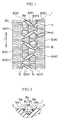
- reference numeral 1 denotes a tread surface, and three main grooves 2 are so disposed on this tread surface as to extend in a tire circumferential direction T. Both main grooves 2X on the tire external side extend straight while the other one main groove 2Y is disposed zigzag on a tire equator at the tread center portion.
- a plurality of transverse grooves 3 extending in a tire width-wise direction are disposed at a predetermined pitch in the tire circumferential direction, and a large number of blocks 4 are defined as land portions by these main grooves 2 and transverse grooves 3.
- Each block 4Y at the tread center portion between both main grooves 2X is shaped into a pentagonal shape by transverse grooves 3Y1 extending slantingly with respect to the tire width-wise direction between both main grooves 2X and transverse grooves 3Y2 extending in the tire width-wise direction between the main grooves 2X and the main groove 2Y.
- the blocks 4X at the shoulder portions on the tire external side from both main grooves 2X are arranged so that their front and rear groove walls orthogonally cross the tire circumferential direction by the transverse grooves 3X extending in the tire width-wise direction.
- the kerfs 5Y disposed in the block 4Y are shaped into a straight shape.
- Each kerf 5X disposed in the block 4X has a shape such that both end portions thereof are straight and the intermediate portion connecting with both end portions is zigzag.
- Each kerf 5 is formed and cut into a depth near the groove bottom of the gain groove 2.
- step portions 10 are formed at both groove walls of the main groove 2.
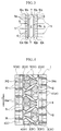
- both groove walls 2a of each main groove 2 are shaped into a step shape having two stages of step portions 10A and 10B as shown in Fig. 2.
- Straight kerfs 5a, 6 and 7 extending in the tire width-wise direction, which is the same as the direction of the kerfs 5, are formed on the upper surfaces 10a and 10b of the step portions 10A and 10B expanding to each groove wall 2a as shown in Fig. 3.
- Each kerf 5a is formed by extending each kerf 5 disposed in the block 4 and communicates with the main groove 2 while crossing transversely the upper surface 10a, 10b of each step portion 10a, 10B.
- Each kerf 6 is dispose on the step portion 10A, 10B and crosses transversely and completely the upper surfaces 10a, 10b and one of its end is open to the main groove 2.
- Each kerf 7 is formed on the step portion 10B of the lower stage and crosses transversely the upper surface 10b as a whole and one of its ends is connected to the main groove 2.
- Kerfs 5a and 6 whose gaps are narrowed to give more density than the kerfs 5 positioned on the adjacent block surfaces, are disposed on the step portion 10A of upper stage in the tire circumferential direction T. Kerfs 5a, 6 and 7, whose gaps are narrower to give more density than the kerfs on the step portion 10A of upper stage, are disposed on the step portion 10B of the lower stage.
- the step portions 10A, 10B are disposed on the groove walls 2a by utilizing main groove 2 and a greater number of kerfs 5a, 6, 7 than the number of kerfs 5 positioned on the surface block 4 are disposed in the tire circumferential direction.
- the kerfs 5a, 6 and 7 can exhibit the edge effect against the snow poles and the mud poles entering the main groove 2 when the car drives on a snow road or a dirt road. Consequently, the edge quantity can be increased effectively without dividing finely the blocks or without increasing the number of kerfs on the blocks as in the conventional counter-measures for the snow roads and the dirt roads.
- braking/driving performance in driving on the snow roads and the dirt roads can be improved without inviting the drop of dry performance resulting from the decrease of the surface area and rigidity of the blocks.
- the step portions 10 are disposed on both groove walls of the transverse grooves 3Y1 and 3Y2.
- Kerfs 5a, 6 and 7 are formed on the step portions 10 disposed on both groove walls 3Ya of each transverse groove 3Y1 inclining to the tire width-wise direction, in the same way as in the case of the step portions 10 of both groove walls 2a of the main groove 2. Since the kerfs extending in the tire width-wise direction are disposed on the step portions of the groove walls 3Ya of the transverse grooves 3Y1 inclining in the tire circumferential direction more densely than the kerfs 5Y of the blocks, the edge quantity can be increased and braking/driving performance in driving on the snow roads and the dirt roads can be further improved.
- Fig. 4 shows another example of the pneumatic tire according to the present invention.
- the step portions 10 are disposed further on both groove walls 3Xa of the transverse grooves 3X of the shoulder portions.
- a plurality of kerfs 8 reaching a depth near the groove bottom of each transverse groove 3 are so disposed as to oppose one another with a predetermined gap on both front and rear sides, in the tire circumferential direction, of each block 4X of the shoulder portion.
- Each kerf 8 extends while crossing orthogonally the tire width-wise direction, and only one of its ends communicates with the transverse groove 3.
- the step portions 10 having the same construction as described above are disposed on both groove walls 3Xa of each transverse groove 3X to which these kerfs 8 are open.
- the kerfs 5a, 6 and 7 formed on the upper surfaces 10a and 10b of the two stages of the step portions 10A and 10B extend in the tire circumferential direction in the same way as the kerfs 8, and one of the ends of each kerf is open to the transverse groove 3.
- the step portions 10 are disposed also on the groove walls 3Xa of the transverse grooves 3X defining the front and rear portions of the block 4X having the kerfs 8 formed in this way in the tire circumferential direction, and the kerfs 5a, 6 and 7 extending in the same direction as the kerfs 8 are disposed on the step portions 10 more densely than the kerfs 8 on the surface of the blocks 4X.
- the edge effect in the tire width-wise direction that is necessary for supporting the centrifugal force when the car turns can be improved in addition to the edge effect in the tire circumferential direction that is necessary for braking and driving when the car drives straight.
- both of braking/driving performance and turning performance during driving on the snow roads and the dirt roads can be improved without lowering dry performance.
- the ground contact pressure of the tread center portion becomes higher during straight driving and the ground contact pressure of the shoulder portions becomes higher during turning. Therefore, the effects described above can be further improved by constituting the blocks 4Y at the center portion and the blocks 4X at the shoulder portions in the same way as the tread pattern shown in Fig. 4.
- the step portions 10 are shown formed in two stages, but one, or not less than three stages, may be disposed. Preferably, two or three stages of step portions 10 are disposed.
- the step portions are disposed in a plurality of stages and slot-like kerfs are formed in these stage portions, the number of kerfs are preferably increased so that the gaps between them become progressively smaller towards the lower stages on the groove bottom side. As a result, driving performance can be improved more effectively while avoiding the drop of the block rigidity.
- the number of kerfs disposed on each step portion 10A, 10B is preferably increased to 1.5 to 6 times the number of kerfs disposed in the stage portion immediately above each stage (the number of kerfs disposed in the block 4 in the case of the uppermost stage portion 10A).
- the gaps of the kerfs disposed on the stage portions preferably become progressively smaller towards the lower stages at a rate of 1/1.5 to 1/6 of the kerf gaps disposed on the step portion of the block (land portion).
- the step portions 10 are disposed on both groove walls of the grooves 2 and 3, but it is also possible to dispose the step portions 10 on only one of the groove walls and to form the kerfs 5a, 6 and 7 on them.
- the depth of the kerfs 5a, 6 and 7 is preferably the same as the depth of the kerfs 5 of the block 4, and preferably reaches a depth near the groove bottom of the grooves 2 and 3.
- the upper surfaces 10a and 10b of the step portions 10A and 10B are shaped into the flat surfaces in parallel with the adjacent block surfaces in the embodiment shown in Figs. 1 and 4 but they may be slope surfaces whose side facing the grooves is lowered.
- Fig. 4 represents the example where the step portions and the kerfs are disposed on the groove walls of the main grooves 2 and the transverse grooves 3, respectively, but the step portions and the kerfs may be disposed on only the transverse grooves 3. According to this construction, turning performance on the snow road and the dirt road can be improved without lowering dry performance.
- the land portion in the present invention may be a land portion comprising ribs divided and defined by at least one main groove, and the transverse grooves may be lug grooves.
- pneumatic tire for passenger cars in the present invention means those pneumatic tires which are used for ordinary passenger cars and recreational vehicles (RV) for home use with the exception of heavy load pneumatic tires for trucks and buses and pneumatic tires for light trucks for transporting cargos.
- RV recreational vehicles
- Pneumatic tires 1, 2 according to the present invention, a comparative pneumatic tire and a conventional pneumatic tire were manufactured.
- the size of all of these tires is 265/70R15.
- the tire 1 of the invention has a block pattern shown in Fig. 1 disposing two stages of step portions on both groove walls of main grooves and disposing kerfs on these step portions more densely than kerfs disposed on the blocks.
- the tire 2 of the invention has kerfs on the two stages of step portions disposed on both groove walls of the transverse grooves inclining in a tire width-wise direction and crossing the main grooves in addition to the construction of the tire 1.
- the comparative tire has the same number of kerfs on the step portions as the number of kerfs on the block in the tire 1, and a conventional tire doesn't have the step portions and the kerfs in the tire 1.
- the kerfs were disposed at a 6 mm pitch in each block, at a 3 mm pitch on the step portion of the upper stage and at a 1.5 mm pitch on the step portion of the lower stage.
- the ratio of increment of the kerfs was twice for each stage with respect to the upper stage.
- test tires were fitted to a rim having a rim size of 15 ⁇ 7JJ, and these tires were fitted at a pneumatic pressure of 200 kPa to a passenger car of a 3,000 cc class, and braking/driving performance on both snow and dirt roads and maneuvering stability on a dry road were evaluated under the following conditions.
- the test results were tabulated in Table 1.
- a feeling test by test drivers was carried out in a test course under a dry state and the result was expressed by using the value of the conventional tire as an index value of 100. The greater this value, the more excellent dry road maneuvering stability.
- Tire 1 of the invention Tire 2 of the invention Comparative Tire Conventional Tire snow road driving/braking performance 110 114 103 100 dirt road braking/driving performance 105 107 102 100 dry road maneuvering stability 100 100 100 100 100 100
- braking/driving performance on both the snow and dirt roads could be improved further by disposing the step portions on both groove walls of each transverse groove which was so inclined in the tire width-wise direction as to cross the main groove, and disposing the kerfs on these step portions more densely than the kerfs of the blocks.
- the tire 3 of the invention has a block pattern with kerfs on each block shown in Fig. 4 disposing two stages of step portions on both groove walls of the main grooves and the transverse grooves slantingly crossing the main groove in a tire width-wise direction and disposing the kerfs on these step portions more densely than the kerfs disposed on the blocks.
- the tire 4 of the invention has further two stages of step portions on both groove walls of the transverse grooves in the shoulder portions and kerfs on them more densely than the kerfs on the blocks in addition to the construction of the Tire 3.
- the tire 5 of the invention has a same number of kerfs on the step portions of the transverse grooves in the shoulder portions as the number of kerfs of the blocks in the tire 4.
- Example 2 Each test tire was fitted to a passenger car of a 3,000 cc class in the same way as in Example 1, and an evaluation test of turning performance on the snow and dirt roads was carried out under the following measurement condition. Further, dry road maneuvering stability evaluation test was conducted under the measurement condition described above, and the results were tabulated in Table 2. In Table 2, however, dry road maneuvering stability was expressed by using the value of the tire 3 of the invention as an index value of 100.
- the groove walls of the grooves are shaped into the step shape and a plurality of kerfs are disposed on these step portions more densely than the kerfs disposed on the land portions. Therefore, the kerfs disposed on the step portions exhibit the edge effect against the snow columns and the mud columns entering the grooves during driving on the snow road and the dirt road. As a result, driving performance on the snow and dirt roads can be improved without spoiling dry performance.
- the present invention having the excellent effects described above can be utilized extremely effectively for pneumatic tires for passenger cars driving on the snow road and the dirt road such as pneumatics tire for RVs (recreation vehicles).
Landscapes
- Engineering & Computer Science (AREA)
- Mechanical Engineering (AREA)
- Tires In General (AREA)
Applications Claiming Priority (4)
| Application Number | Priority Date | Filing Date | Title |
|---|---|---|---|
| JP4762696 | 1996-03-05 | ||
| JP4762696 | 1996-03-05 | ||
| JP47626/96 | 1996-03-05 | ||
| PCT/JP1997/000684 WO1997032741A1 (fr) | 1996-03-05 | 1997-03-05 | Pneumatique pour des vehicules pour passagers |
Publications (3)
| Publication Number | Publication Date |
|---|---|
| EP0825039A1 true EP0825039A1 (fr) | 1998-02-25 |
| EP0825039A4 EP0825039A4 (fr) | 2001-01-10 |
| EP0825039B1 EP0825039B1 (fr) | 2003-02-19 |
Family
ID=12780436
Family Applications (1)
| Application Number | Title | Priority Date | Filing Date |
|---|---|---|---|
| EP97905453A Expired - Lifetime EP0825039B1 (fr) | 1996-03-05 | 1997-03-05 | Pneumatique pour des vehicules pour passagers |
Country Status (4)
| Country | Link |
|---|---|
| US (1) | US5957180A (fr) |
| EP (1) | EP0825039B1 (fr) |
| DE (1) | DE69719128T2 (fr) |
| WO (1) | WO1997032741A1 (fr) |
Cited By (4)
| Publication number | Priority date | Publication date | Assignee | Title |
|---|---|---|---|---|
| GB2326386B (en) * | 1997-06-19 | 2001-11-21 | Sumitomo Rubber Ind | Vehicle tyre tread groove with radially inward extension |
| DE10258812A1 (de) * | 2002-12-17 | 2004-07-01 | Continental Aktiengesellschaft | Fahrzeugluftreifen mit Spikes zum Einsatz unter winterlichen Fahrbedingungen |
| FR2890600A1 (fr) * | 2005-09-15 | 2007-03-16 | Michelin Soc Tech | Dispositif anti-usure irreguliere pour bande de roulement de pneumatique |
| EP2803502A1 (fr) * | 2013-05-15 | 2014-11-19 | Sumitomo Rubber Industries, Ltd. | Pneu |
Families Citing this family (25)
| Publication number | Priority date | Publication date | Assignee | Title |
|---|---|---|---|---|
| US6189586B1 (en) * | 1998-10-15 | 2001-02-20 | Warren L. Guidry | Pneumatic rubber tire for on/off-road vehicles |
| JP4274296B2 (ja) * | 2000-01-12 | 2009-06-03 | 横浜ゴム株式会社 | 空気入りタイヤ |
| JP4527968B2 (ja) * | 2003-11-26 | 2010-08-18 | 住友ゴム工業株式会社 | 空気入りタイヤ |
| JP4137900B2 (ja) * | 2005-02-22 | 2008-08-20 | 住友ゴム工業株式会社 | 農用車輪 |
| DE602006011776D1 (de) * | 2005-11-16 | 2010-03-04 | Yokohama Rubber Co Ltd | Luftreifen |
| JP5038649B2 (ja) * | 2006-04-18 | 2012-10-03 | 東洋ゴム工業株式会社 | 空気入りタイヤ |
| JP4738276B2 (ja) * | 2006-08-03 | 2011-08-03 | 株式会社ブリヂストン | 空気入りタイヤ |
| JP4968895B2 (ja) * | 2006-09-25 | 2012-07-04 | 東洋ゴム工業株式会社 | 悪路走行用空気入りタイヤ |
| JP2009046052A (ja) * | 2007-08-21 | 2009-03-05 | Bridgestone Corp | 空気入りタイヤ |
| JP4990396B2 (ja) * | 2007-08-24 | 2012-08-01 | ソシエテ ド テクノロジー ミシュラン | サイドウォール保護手段を備えたタイヤ |
| JP5160870B2 (ja) | 2007-12-10 | 2013-03-13 | 東洋ゴム工業株式会社 | 空気入りタイヤ |
| JP5150421B2 (ja) * | 2008-09-08 | 2013-02-20 | 株式会社ブリヂストン | 空気入りタイヤ |
| JP5421800B2 (ja) * | 2010-01-18 | 2014-02-19 | 株式会社ブリヂストン | 空気入りタイヤ |
| DE102010060945A1 (de) * | 2010-12-01 | 2012-06-06 | Continental Reifen Deutschland Gmbh | Fahrzeugluftreifen |
| JP5771407B2 (ja) * | 2011-02-16 | 2015-08-26 | 株式会社ブリヂストン | 空気入りタイヤ |
| JP5882611B2 (ja) * | 2011-06-24 | 2016-03-09 | 株式会社ブリヂストン | タイヤ |
| JP5440590B2 (ja) * | 2011-11-14 | 2014-03-12 | 横浜ゴム株式会社 | 空気入りタイヤ |
| EP2990233B1 (fr) * | 2013-04-24 | 2017-05-31 | Bridgestone Corporation | Pneu |
| JP6965671B2 (ja) * | 2017-10-03 | 2021-11-10 | 住友ゴム工業株式会社 | タイヤ |
| USD858427S1 (en) | 2017-11-02 | 2019-09-03 | Cooper Tire & Rubber Company | Tire tread |
| USD858428S1 (en) | 2017-11-02 | 2019-09-03 | Cooper Tire & Rubber Company | Tire tread |
| JP7000836B2 (ja) * | 2017-12-15 | 2022-01-19 | 住友ゴム工業株式会社 | タイヤ |
| JP7346960B2 (ja) * | 2019-07-16 | 2023-09-20 | 住友ゴム工業株式会社 | タイヤ |
| JP7380055B2 (ja) * | 2019-10-10 | 2023-11-15 | 住友ゴム工業株式会社 | タイヤ |
| DE202019106882U1 (de) * | 2019-12-10 | 2020-03-09 | Apollo Tyres Global R&D B.V. | Reifenlauffläche |
Citations (4)
| Publication number | Priority date | Publication date | Assignee | Title |
|---|---|---|---|---|
| GB565477A (en) * | 1942-03-18 | 1944-11-13 | Firestone Tire & Rubber Co | Improvements in or relating to vehicle tires |
| US4114671A (en) * | 1976-01-26 | 1978-09-19 | Industrie Pirelli S.P.A. | Pneumatic tire for vehicles having improved handling and road gripping |
| EP0393873A2 (fr) * | 1989-04-21 | 1990-10-24 | Sp Reifenwerke Gmbh | Pneumatique pour véhicules |
| EP0855292A1 (fr) * | 1997-01-28 | 1998-07-29 | PIRELLI COORDINAMENTO PNEUMATICI S.p.A. | Pneumatiques et bande de roulement pour pneu, en particulier pour camions et similaires |
Family Cites Families (16)
| Publication number | Priority date | Publication date | Assignee | Title |
|---|---|---|---|---|
| US2094636A (en) * | 1934-11-24 | 1937-10-05 | Us Rubber Co | Tire |
| US3893498A (en) * | 1974-06-13 | 1975-07-08 | Firestone Tire & Rubber Co | Pneumatic tire |
| US3951193A (en) * | 1974-07-11 | 1976-04-20 | The Goodyear Tire & Rubber Company | Groove in the tread of a tire |
| JPS58156405A (ja) * | 1982-03-11 | 1983-09-17 | Yokohama Rubber Co Ltd:The | 乗用車用空気入りラジアルタイヤ |
| US5492161A (en) * | 1985-01-19 | 1996-02-20 | Toyo Tire & Rubber Company, Limited | Pneumatic tire with groove steps having sipes |
| JPS61166708A (ja) * | 1985-01-19 | 1986-07-28 | Toyo Tire & Rubber Co Ltd | 空気入りタイヤ |
| US4854358A (en) * | 1985-06-26 | 1989-08-08 | Sumitomo Rubber Industries, Ltd. | Tread pattern for a heavy load pneumatic tire which changes from a block pattern to a rib pattern with wear |
| US4703788A (en) * | 1985-09-17 | 1987-11-03 | Sumitomo Rubber Industries, Ltd. | Tire tread with zig-zag grooves with projections in groove |
| JPS6416406A (en) * | 1987-07-10 | 1989-01-19 | Bridgestone Corp | Pneumatic radial tyre |
| JPH01215604A (ja) * | 1988-02-23 | 1989-08-29 | Toyo Tire & Rubber Co Ltd | 溝底にサイプを有する重荷重用空気入りラジアルタイヤ |
| JP2744446B2 (ja) * | 1988-11-09 | 1998-04-28 | 株式会社ブリヂストン | 車両用スノータイヤ |
| JPH03143707A (ja) * | 1989-10-31 | 1991-06-19 | Bridgestone Corp | 冬期使用に適した重荷重用空気入りタイヤ |
| JPH03197208A (ja) * | 1989-12-26 | 1991-08-28 | Yokohama Rubber Co Ltd:The | 空気入りタイヤ |
| JP3270177B2 (ja) * | 1993-03-19 | 2002-04-02 | 横浜ゴム株式会社 | 空気入りラジアルタイヤ |
| JPH06286422A (ja) * | 1993-03-30 | 1994-10-11 | Yokohama Rubber Co Ltd:The | 雪氷路用空気入りタイヤ |
| FI944892A (fi) * | 1993-11-18 | 1995-08-18 | Bridgestone Corp | Pneumaattinen rengas |
-
1997
- 1997-03-05 EP EP97905453A patent/EP0825039B1/fr not_active Expired - Lifetime
- 1997-03-05 WO PCT/JP1997/000684 patent/WO1997032741A1/fr active IP Right Grant
- 1997-03-05 DE DE69719128T patent/DE69719128T2/de not_active Expired - Fee Related
- 1997-03-05 US US08/945,550 patent/US5957180A/en not_active Expired - Fee Related
Patent Citations (4)
| Publication number | Priority date | Publication date | Assignee | Title |
|---|---|---|---|---|
| GB565477A (en) * | 1942-03-18 | 1944-11-13 | Firestone Tire & Rubber Co | Improvements in or relating to vehicle tires |
| US4114671A (en) * | 1976-01-26 | 1978-09-19 | Industrie Pirelli S.P.A. | Pneumatic tire for vehicles having improved handling and road gripping |
| EP0393873A2 (fr) * | 1989-04-21 | 1990-10-24 | Sp Reifenwerke Gmbh | Pneumatique pour véhicules |
| EP0855292A1 (fr) * | 1997-01-28 | 1998-07-29 | PIRELLI COORDINAMENTO PNEUMATICI S.p.A. | Pneumatiques et bande de roulement pour pneu, en particulier pour camions et similaires |
Non-Patent Citations (1)
| Title |
|---|
| See also references of WO9732741A1 * |
Cited By (8)
| Publication number | Priority date | Publication date | Assignee | Title |
|---|---|---|---|---|
| GB2326386B (en) * | 1997-06-19 | 2001-11-21 | Sumitomo Rubber Ind | Vehicle tyre tread groove with radially inward extension |
| DE10258812A1 (de) * | 2002-12-17 | 2004-07-01 | Continental Aktiengesellschaft | Fahrzeugluftreifen mit Spikes zum Einsatz unter winterlichen Fahrbedingungen |
| FR2890600A1 (fr) * | 2005-09-15 | 2007-03-16 | Michelin Soc Tech | Dispositif anti-usure irreguliere pour bande de roulement de pneumatique |
| EP1764237A2 (fr) * | 2005-09-15 | 2007-03-21 | Societe de Technologie Michelin | Dispositif anti-usure irreguliere pour bande de roulement de pneumatique. |
| EP1764237A3 (fr) * | 2005-09-15 | 2013-05-01 | Compagnie Generale Des Etablissements Michelin | Dispositif anti-usure irreguliere pour bande de roulement de pneumatique. |
| EP2803502A1 (fr) * | 2013-05-15 | 2014-11-19 | Sumitomo Rubber Industries, Ltd. | Pneu |
| CN104163079A (zh) * | 2013-05-15 | 2014-11-26 | 住友橡胶工业株式会社 | 充气轮胎 |
| US9731560B2 (en) | 2013-05-15 | 2017-08-15 | Sumitomo Rubber Industries, Ltd. | Pneumatic tire |
Also Published As
| Publication number | Publication date |
|---|---|
| US5957180A (en) | 1999-09-28 |
| DE69719128D1 (de) | 2003-03-27 |
| WO1997032741A1 (fr) | 1997-09-12 |
| EP0825039B1 (fr) | 2003-02-19 |
| DE69719128T2 (de) | 2003-10-23 |
| EP0825039A4 (fr) | 2001-01-10 |
Similar Documents
| Publication | Publication Date | Title |
|---|---|---|
| EP0825039B1 (fr) | Pneumatique pour des vehicules pour passagers | |
| EP2261064B1 (fr) | Pneu | |
| US7921891B2 (en) | Pneumatic tire for traveling on off road | |
| EP1961587B1 (fr) | Pneu non clouté | |
| US4955415A (en) | Pneumatic radial tire with groove platforms to prevent stone entrapment | |
| EP0841199A2 (fr) | Bandage pneumatique | |
| EP3421263A1 (fr) | Pneumatique | |
| CN107433824B (zh) | 轮胎 | |
| EP3098090B1 (fr) | Pneu d'hiver | |
| JP7035769B2 (ja) | タイヤ | |
| US5873399A (en) | Pneumatic studless tires including wave-shaped sipes | |
| JP4268576B2 (ja) | 空気入りタイヤ | |
| JP6769181B2 (ja) | タイヤ | |
| EP0715973A2 (fr) | Bandages pneumatiques pour roulage sur routes enneigées/verglacées | |
| JP5032829B2 (ja) | 空気入りタイヤ | |
| US5804000A (en) | Pneumatic radial tire including main grooves and sub-grooves | |
| JP4800610B2 (ja) | 空気入りラジアルタイヤ | |
| JPS62231803A (ja) | 重荷重用空気入りタイヤ | |
| EP3828011B1 (fr) | Bande de roulement de pneumatique | |
| KR100604077B1 (ko) | 오프로드용 고성능 공기입 타이어의 트레드 패턴구조 | |
| JPH10244813A (ja) | 空気入りタイヤ | |
| EP0890456B1 (fr) | Bandage pneumatique radial toutes saisons | |
| JP3197727B2 (ja) | 空気入りタイヤ | |
| CN111532087B (zh) | 轮胎 | |
| EP1145873B1 (fr) | Bandage pneumatique pour véhicule |
Legal Events
| Date | Code | Title | Description |
|---|---|---|---|
| PUAI | Public reference made under article 153(3) epc to a published international application that has entered the european phase |
Free format text: ORIGINAL CODE: 0009012 |
|
| 17P | Request for examination filed |
Effective date: 19971217 |
|
| AK | Designated contracting states |
Kind code of ref document: A1 Designated state(s): DE FR GB IT |
|
| A4 | Supplementary search report drawn up and despatched |
Effective date: 20001128 |
|
| AK | Designated contracting states |
Kind code of ref document: A4 Designated state(s): DE FR GB IT |
|
| RIC1 | Information provided on ipc code assigned before grant |
Free format text: 7B 60C 11/11 A, 7B 60C 11/12 B, 7B 60C 11/13 B |
|
| GRAH | Despatch of communication of intention to grant a patent |
Free format text: ORIGINAL CODE: EPIDOS IGRA |
|
| GRAH | Despatch of communication of intention to grant a patent |
Free format text: ORIGINAL CODE: EPIDOS IGRA |
|
| GRAA | (expected) grant |
Free format text: ORIGINAL CODE: 0009210 |
|
| RAP1 | Party data changed (applicant data changed or rights of an application transferred) |
Owner name: THE YOKOHAMA RUBBER CO., LTD. |
|
| AK | Designated contracting states |
Designated state(s): DE FR GB IT |
|
| REG | Reference to a national code |
Ref country code: GB Ref legal event code: FG4D |
|
| REF | Corresponds to: |
Ref document number: 69719128 Country of ref document: DE Date of ref document: 20030327 Kind code of ref document: P |
|
| ET | Fr: translation filed | ||
| PLBE | No opposition filed within time limit |
Free format text: ORIGINAL CODE: 0009261 |
|
| STAA | Information on the status of an ep patent application or granted ep patent |
Free format text: STATUS: NO OPPOSITION FILED WITHIN TIME LIMIT |
|
| 26N | No opposition filed |
Effective date: 20031120 |
|
| PGFP | Annual fee paid to national office [announced via postgrant information from national office to epo] |
Ref country code: DE Payment date: 20060302 Year of fee payment: 10 |
|
| PGFP | Annual fee paid to national office [announced via postgrant information from national office to epo] |
Ref country code: FR Payment date: 20060308 Year of fee payment: 10 |
|
| PGFP | Annual fee paid to national office [announced via postgrant information from national office to epo] |
Ref country code: IT Payment date: 20060331 Year of fee payment: 10 |
|
| GBPC | Gb: european patent ceased through non-payment of renewal fee |
Effective date: 20070305 |
|
| REG | Reference to a national code |
Ref country code: FR Ref legal event code: ST Effective date: 20071130 |
|
| PG25 | Lapsed in a contracting state [announced via postgrant information from national office to epo] |
Ref country code: DE Free format text: LAPSE BECAUSE OF NON-PAYMENT OF DUE FEES Effective date: 20071002 |
|
| PG25 | Lapsed in a contracting state [announced via postgrant information from national office to epo] |
Ref country code: GB Free format text: LAPSE BECAUSE OF NON-PAYMENT OF DUE FEES Effective date: 20070305 |
|
| PG25 | Lapsed in a contracting state [announced via postgrant information from national office to epo] |
Ref country code: FR Free format text: LAPSE BECAUSE OF NON-PAYMENT OF DUE FEES Effective date: 20070402 |
|
| PGFP | Annual fee paid to national office [announced via postgrant information from national office to epo] |
Ref country code: GB Payment date: 20060301 Year of fee payment: 10 |
|
| PG25 | Lapsed in a contracting state [announced via postgrant information from national office to epo] |
Ref country code: IT Free format text: LAPSE BECAUSE OF NON-PAYMENT OF DUE FEES Effective date: 20070305 |