EP0823974B1 - Mehrkarussellträger und karussellhandhabungsvorrichtung - Google Patents
Mehrkarussellträger und karussellhandhabungsvorrichtung Download PDFInfo
- Publication number
- EP0823974B1 EP0823974B1 EP97914824.4A EP97914824A EP0823974B1 EP 0823974 B1 EP0823974 B1 EP 0823974B1 EP 97914824 A EP97914824 A EP 97914824A EP 0823974 B1 EP0823974 B1 EP 0823974B1
- Authority
- EP
- European Patent Office
- Prior art keywords
- tray
- carrier
- shaft
- actuator
- trays
- Prior art date
- Legal status (The legal status is an assumption and is not a legal conclusion. Google has not performed a legal analysis and makes no representation as to the accuracy of the status listed.)
- Expired - Lifetime
Links
- 230000007246 mechanism Effects 0.000 title claims description 66
- 230000003287 optical effect Effects 0.000 claims description 25
- 230000000694 effects Effects 0.000 claims description 11
- 238000005070 sampling Methods 0.000 description 21
- 230000032258 transport Effects 0.000 description 9
- 230000000295 complement effect Effects 0.000 description 7
- 235000014676 Phragmites communis Nutrition 0.000 description 5
- 230000008878 coupling Effects 0.000 description 5
- 238000010168 coupling process Methods 0.000 description 5
- 238000005859 coupling reaction Methods 0.000 description 5
- 230000009977 dual effect Effects 0.000 description 4
- 238000012795 verification Methods 0.000 description 4
- 230000009467 reduction Effects 0.000 description 3
- 238000004140 cleaning Methods 0.000 description 2
- 238000010276 construction Methods 0.000 description 2
- 238000004128 high performance liquid chromatography Methods 0.000 description 2
- 239000003643 water by type Substances 0.000 description 2
- 238000013019 agitation Methods 0.000 description 1
- 239000000969 carrier Substances 0.000 description 1
- 238000004587 chromatography analysis Methods 0.000 description 1
- 230000000881 depressing effect Effects 0.000 description 1
- 238000007689 inspection Methods 0.000 description 1
- 238000004811 liquid chromatography Methods 0.000 description 1
- 238000012423 maintenance Methods 0.000 description 1
- 230000008439 repair process Effects 0.000 description 1
- 239000007787 solid Substances 0.000 description 1
- XLYOFNOQVPJJNP-UHFFFAOYSA-N water Substances O XLYOFNOQVPJJNP-UHFFFAOYSA-N 0.000 description 1
Images


Classifications
-
- G—PHYSICS
- G01—MEASURING; TESTING
- G01N—INVESTIGATING OR ANALYSING MATERIALS BY DETERMINING THEIR CHEMICAL OR PHYSICAL PROPERTIES
- G01N35/00—Automatic analysis not limited to methods or materials provided for in any single one of groups G01N1/00 - G01N33/00; Handling materials therefor
- G01N35/02—Automatic analysis not limited to methods or materials provided for in any single one of groups G01N1/00 - G01N33/00; Handling materials therefor using a plurality of sample containers moved by a conveyor system past one or more treatment or analysis stations
- G01N35/04—Details of the conveyor system
-
- G—PHYSICS
- G01—MEASURING; TESTING
- G01N—INVESTIGATING OR ANALYSING MATERIALS BY DETERMINING THEIR CHEMICAL OR PHYSICAL PROPERTIES
- G01N35/00—Automatic analysis not limited to methods or materials provided for in any single one of groups G01N1/00 - G01N33/00; Handling materials therefor
- G01N35/02—Automatic analysis not limited to methods or materials provided for in any single one of groups G01N1/00 - G01N33/00; Handling materials therefor using a plurality of sample containers moved by a conveyor system past one or more treatment or analysis stations
- G01N35/04—Details of the conveyor system
- G01N2035/0439—Rotary sample carriers, i.e. carousels
- G01N2035/0441—Rotary sample carriers, i.e. carousels for samples
-
- G—PHYSICS
- G01—MEASURING; TESTING
- G01N—INVESTIGATING OR ANALYSING MATERIALS BY DETERMINING THEIR CHEMICAL OR PHYSICAL PROPERTIES
- G01N35/00—Automatic analysis not limited to methods or materials provided for in any single one of groups G01N1/00 - G01N33/00; Handling materials therefor
- G01N35/02—Automatic analysis not limited to methods or materials provided for in any single one of groups G01N1/00 - G01N33/00; Handling materials therefor using a plurality of sample containers moved by a conveyor system past one or more treatment or analysis stations
- G01N35/04—Details of the conveyor system
- G01N2035/0439—Rotary sample carriers, i.e. carousels
- G01N2035/0451—Rotary sample carriers, i.e. carousels composed of interchangeable sectors
-
- G—PHYSICS
- G01—MEASURING; TESTING
- G01N—INVESTIGATING OR ANALYSING MATERIALS BY DETERMINING THEIR CHEMICAL OR PHYSICAL PROPERTIES
- G01N35/00—Automatic analysis not limited to methods or materials provided for in any single one of groups G01N1/00 - G01N33/00; Handling materials therefor
- G01N35/02—Automatic analysis not limited to methods or materials provided for in any single one of groups G01N1/00 - G01N33/00; Handling materials therefor using a plurality of sample containers moved by a conveyor system past one or more treatment or analysis stations
- G01N35/04—Details of the conveyor system
- G01N2035/0439—Rotary sample carriers, i.e. carousels
- G01N2035/0453—Multiple carousels working in parallel
-
- G—PHYSICS
- G01—MEASURING; TESTING
- G01N—INVESTIGATING OR ANALYSING MATERIALS BY DETERMINING THEIR CHEMICAL OR PHYSICAL PROPERTIES
- G01N35/00—Automatic analysis not limited to methods or materials provided for in any single one of groups G01N1/00 - G01N33/00; Handling materials therefor
- G01N35/02—Automatic analysis not limited to methods or materials provided for in any single one of groups G01N1/00 - G01N33/00; Handling materials therefor using a plurality of sample containers moved by a conveyor system past one or more treatment or analysis stations
- G01N35/025—Automatic analysis not limited to methods or materials provided for in any single one of groups G01N1/00 - G01N33/00; Handling materials therefor using a plurality of sample containers moved by a conveyor system past one or more treatment or analysis stations having a carousel or turntable for reaction cells or cuvettes
Definitions
- the present invention relates to autosampler mechanisms for use in automated sampling systems such as used at the front end of High Performance Liquid Chromatography (HPLC) systems, and more particularly to a sample handling system that includes a carrier for manipulating a plurality of carousels or trays of sample vials.
- HPLC High Performance Liquid Chromatography
- Automated sampling systems are known for handling multiple sample sources, such as a tray with a plurality of vials with samples for processing in a liquid chromatography system.
- samples are stored in vials that are in turn stored on trays.
- the systems include transport facilities for transporting the sample vials to a sampling station, by positioning the trays under the sampling station and rotating the trays positioning each of the individual vials, one at a time, beneath the sampling station for sampling.
- Known systems typically involve a belt drive mechanism in the transport system.
- U.S. Patent No. 4,622,457 (“the 457 patent”) describes an autosampler mechanism that positions a tray of sample vials beneath a sampling station and lifts each vial individually from the tray for sampling by a stationary sampling mechanism or needle.
- the sample vials are transported to and away from the sampling station by a transport system that includes a rotatable platter and four planetary trays carried by the rotatable platter.
- a belt driven clutch and brake drive system described in the '457 patent facilitates rotation of the rotatable platter, and rotation of the trays relative to the rotatable platter so that any sample vial can be positioned beneath the sample station
- the clutch and brake drive system requires an elaborate arrangement ofdrive shafts, pulleys and a drive belt to effect rotation of the platter and trays.
- a clutch electromagnet and an electromagnetic brake are also implemented in the '457 patent to effect three modes of operation: a braked mode wherein the tray mechanism is in a fixed, braked position; a platter rotation mode wherein the platter is rotated to rotate the four planetary trays in order to position a selected tray beneath the sampling station, and a tray rotation mode wherein the platter is fixed but the trays are rotated with respect to the platter.
- Positioning of the sample vials in the '457 device is effected by an optical sensor located inside the sample compartment.
- Samples can be identified by slot location in the tray in accordance with "identifying elements" located under each slot.
- Each tray has an orientation spot located on its outer periphery for reading by the optical sensor.
- Location of the optical sensor(s) in the sample compartment presents a problem in that when the sample compartment is cooled moisture build-up can occur on the sensors and can cause the sensor to misread or not read at all.
- Model 712 and 717 Autosampler systems manufactured by Waters Chromatography (presently Waters Corporation), formerly a division of Millipore Corporation.
- the transport systems of the Model 712 and 717 Autosampler systems nonetheless incorporate belt driven actuators.
- Belt driven systems as discussed suffer disadvantages associated with the flexing and wear of the belt.
- the Model 712 and 717 systems include an optical sensor located in the sample compartment for identifying the location of samples. Again, moisture build-up can occur on sensors located in the sample compartment which may cause the sensor to misread or to not read at all.
- the prior art Water's devices actuated a large, single carousel with a limited capacity of 48 or 96 sample vials.
- JP61-013160 discloses the pre-characterising features of the claimed invention.
- US4849176 , JP62-076465 and DE2733074 disclose similar arrangements.
- the present invention provides a sample handling mechanism including a direct drive carrier for positioning multiple trays or carousels of sample vials and a direct drive carousel handling mechanism that eliminates pulleys and belts and the problems associated therewith.
- the present invention provides a sample handling apparatus (40) for handling multiple trays (10) of sample vials, comprising:
- the trays or carousels handled by the sample handling mechanism according to the invention are individually identifiable, stackable and include a viewing area for identifying and viewing the individual sample vials grouped in a respective carousel.
- the sample handling mechanism consists of two logical drive modules which are integrated into one assembly. A single center line or axis of rotation is effected in each of the drive modules.
- the two logical drive modules include a carrier mechanism that transports five sample carousels to a sampling station, and a carousel drive mechanism which engages a single carousel at the sampling station and presents the appropriate vial to be sampled.
- the carrier mechanism includes a five-position spoke-like carrier portion that is driven by a single drive shaft coupled to a gear reduction stepper motor by a coupling.
- Carrier position is monitored by counting motor steps from a home position or a previous carousel position. Position is verified by an encoder wheel having five positional slots keyed and clamped directly to the drive shaft. Encoder slots are sensed by a dual channel optical interrupter in which one channel is for home verification, and the other is for carousel positional verification.
- the carousel drive mechanism includes a linear actuator portion and a rotary actuator portion on a common center line or axis.
- the linear actuator portion effects engagement and disengagement of the rotary actuator portion with a properly positioned carousel, and includes a linear actuator stepper motor with a motor shaft attached to a lift housing.
- the lift housing holds the rotary actuator portion including a rotary stepper motor, a concentric drive shaft, an encoder wheel attached to the drive shaft and position mechanisms that sense when the drive shaft is in an up position disengaged from a carousel or in a down position engaged with a carousel.
- the encoder wheel attached to the drive shaft is a twentyfour position encoder wheel, each position corresponding to the position of a sample vial in a carousel
- the encoder is keyed and clamped for zero orientation of the shaft to the zero position of the encoder
- the slots in the encoder wheel are sensed by a dual channel interrupter sensor wherein one channel is for verifying home and the other is for verifying individual vial positions.
- the motor(s), encoder wheel, and optical sensor are all located outside the sample compartment.
- features of the invention include individual identification of each carousel within a carrier by a magnet placed in one of six unique locations which actuates a reed switch facilitating counting of steps from a "home" sensor to where the magnet is sensed.
- Incontrast to prior art twelve inch carousels which are much larger and harder to store, carousels designed to be handled according to the invention are smaller and more compact, and are designed to be stackable, thus saving space, which is highly desirable particularly for refrigerated samples.
- the carousels include a viewing portion whereat a sample vial installed in the carousel is left exposed to allow a bar code label to be read by an optional bar code reader.
- the carrier and its interface to a carrier drive shaft is designed with a "no tools" disengagement philosophy to allow the carrier to be manually removed for ease of cleaning the carrier and sample compartment.
- the multiple carousel carrier design provides the ability to add new or stat samples to the system simultaneously with ongoing vial sampling.
- the carousel drive mechanism is configured to effect unidirectional rotation of the carousel to eliminate positional error due to backlash.
- the vertical motion of the lift housing portion of the drive mechanism is decoupled, i.e. it is not affected by the carousel rotary drive motion.
- the sample handling mechanism increases the number of sample vials available for sampling from a typical maximum of 80 or 96, to a present maximum of 120 within substantially the same footprint.
- a flexible design has potential for extensibility by implementing alternative carriers and associated encoder and/or alternative carousels and associated encoder.
- the sample handling mechanism effects handling and actuation or transportation of samples contained in vials.
- the samples are "handled," or positioned proximate to a sampling station by the sample handling mechanism, for processing such as by HPLC apparatus, as known in the art.
- the sample vials are grouped and maintained in individual carousels.
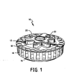
- the carousels (illustrated in Figs. 1 - 3 ) are actuated first by a carrier mechanism ( Fig. 5 ) which transports the carousels into position for rotation by a carousel drive mechanism ( Fig. 6 ).
- the carousel drive mechanism in turn rotates eachcarousel, individually, to position the individual sample vials for sampling.
- each carousel 10 is circular, approximately 5 inches in diameter, and includes twenty four vial positions 12 placed radially on an approximately 4.300 inch bolt circle.
- the vial positions are configured to receive virtually any 2 ml sample vial known in the art.
- the vials (not shown) fit loosely into the vial positions 12 to rest on a solid base 14 thereof
- Each vial position 12 has a viewing window 16 to facilitate inspection, automated or otherwise, of identifying labels, e.g. bar coded labels, that identify the individual vials in the carousel 10
- the carousels 10 are a two piece plastic molded construction comprising a sample positioning portion 18 that is effectively the entirety of the carousel except for a spoke plate portion 20.
- the spoke plate portion 20 is a 1/8 inch thick plastic plate that caps off a spoke-shaped upper portion of the sample positioning portion 18.
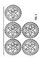
- the spoke plate portion 20 includes a magnet receptacle 22 with a magnet installed therein, that works in conjunction with a reed switch proximate to the carousel drive mechanism 80, as described hereinafter, to facilitate simple, low cost, unique identification of the individual carousels.
- each one of a full complement of carousels handled i.e. five carousels, is uniquely identifiable by locating the magnet receptacle 22 in one of six unique locations corresponding with six spokes on the spoke plate portion 20.
- the unique location, and corresponding unique identification is defined by the location of the magnet receptacle 22 with respect to a drive pin slot 24 located in a recess at the center of the spoke plate portion 20.
- a full complement of carousels has vial sample locations that are uniquely identifiable and successively numbered between 1 and 120
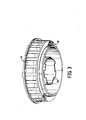
- the spoke-shaped upper portion of the sample positioning portion 18 is configured to engage a plurality of cut-outs 28 on the bottom of the carousels 10, as illustrated in Fig. 3 , to facilitate stacking of the carousels for compact storage when not in use.
- a circular bottom ridge 30 has a circumference just slightly larger than a circumference circumscribing the six spokes of the spoke-shaped upper portion of the sample positioning portion 18 to further ensure stable stacking of the carousels.
- the full complement of carousels is manipulated into position with respect to a sample handling station by a sample handling mechanism according to the invention.
- the sample handling mechanism 40 transporting carousels consists of two logical drive modules which are integrated into one assembly or frame 42.
- a carrier mechanism 50 is a first drive module, that transports five sample carousels 10 to a sampling station (not shown), as required.
- a second drive module is a carousel drive mechanism 80 which engages a single carousel proximate to the sampling station and presents an appropriate vial to the sampling station as programmed and as understood by those skilled in the art.
- the carousels 10 are installed by an operator in an appropriate location of a carrier 52.
- the operator installs the set of carousels in the carrier so that successively numbered carousels are adjacent to one another.
- the carrier 52 is a five-position spoke-like part that has partial-circumference positions 54 for each of five carousels comprising a full complement with sample vial positions numbered 1 - 120.
- Carousels 10 fit removably into respective positions such that the circular bottom ridge 30 of a carousel 10 is snugly embraced by a respective one of the partial-circumference positions 54 to retain the carousel in the carrier 52.
- the carrier 52 is driven by a single drive shaft 56 which it engages with and disengages from in accordance with a "no tools" disengagement philosophy That is, the carrier can be easily, manually removed to facilitate ease of cleaning a sample compartment (not shown) in which the carrier resides. Accordingly, the carrier drive shaft 56 has a drive slot 58 in an engagement end thereof The carrier 52 has a spring-loaded key pin 60 passing through a spring housing 62 A spring 61 is disposed about the spring housing. The spring housing 62 has an open portion (not shown) or cut-out that is sufficient to provide clearance for the drive shaft 56 and permits the carrier to be moved horizontally, to engage and disengage the carrier and carrier drive shaft 56.
- the key pin 60 is biased outwardly from the carrier 52 to engage the slot 58 in the carrier drive shaft 56 when the carrier is disposed on a bearing surface in the sample compartment.
- the carrier includes a boss 64 on a bottom surface thereof which engages a flat bearing surface in the sample compartment.
- Disengagement of the carrier 52 is effected manually by an operator by depressing the spring loaded key pin 60, and pulling the carrier 52 toward the operator to disengage the carrier 52 from the drive shaft 56, when the carrier is in a "home" position, i.e. the open portion on the spring housing is facing away from the operator and the carrier can be moved horizontally toward the front of the sample compartment
- the carrier drive shaft 56 is coupled to a carrier rotary gear reduction stepper motor 64 by a coupling 66, best seen in Fig. 5A .
- the carrier stepper motor 64 is configured so that the carrier 52 rotates counter clockwise only, to eliminate any backlash due to the gear reduced stepper drive.
- the carrier 52 is positioned by the motor 64 by counting motor steps from the home position or a previous carousel position This position is verified by an encoder wheel 68 keyed and clamped directly to the carrier drive shaft 56.
- the encoder wheel 68 is mounted proximate to the coupling 66 which is at an end of the carrier drive shaft 56 distal to the drive slot 58.
- the encoder wheel 68 has five positional slots to correspond to the positions of the five carousels in the carrier 52.
- the encoder wheel 68 is used to verify each of the five positions.
- One of the slots in the encoder wheel is elongated and acts as the home or "A" position to correspond to the position whereat a first carousel of a full complement (i.e. the A carousel with vials 1-24) is located toward the front of the sample compartment and whereat the carrier can be removed by releasing the spring-loaded key pin 60 and moving the carrier horizontally toward the operator as discussed hereinbefore.
- the encoder wheel 68 is keyed to the carrier drive shaft by a hole 70 in the carrier drive shaft 56 that mates with an alignment key hole 72 on the encoder wheel assembly 68. Keying the encoder wheel 68 ensures a positional orientation of the drive slot 58 in the end of the carrier drive shaft 58 that corresponds to the home position on the encoder wheel. Keying also facilitates ease of assembly.
- the slots on the encoder wheel 68 corresponding to the carrier positions are sensed by a dual channel optical interrupter or sensor 74.
- One channel of the optical interrupter is for home verification, and the other for carousel positional verification.
- the sensor 74 is mounted directly on a circuit board 76 which is in turn mounted on brackets 78 that are attached to the frame 42 in a manner allowing only one degree of freedom, to facilitate ease of adjustment.
- the carrier stepper motor 64, encoder wheel 68, and sensor 74, are all disposed in positions outside of the sample compartment.
- a carousel 10 is positioned under the sampling station (not shown), by the carrier mechanism 50 as discussed in detail hereinbefore, it can be engaged for positioning by the carousel drive mechanism 80.
- the carousel drive mechanism 80 is comprised of a linear actuator drive motor 82 which drives a rotary motion carousel drive mechanism 84 up and down in a linear manner.
- the rotary motion carousel drive mechanism 84 is comprisedof a lift housing 86 that houses a rotary gear reduction stepper motor 88 attached a keyed concentric carousel drive shaft 90.
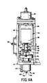
- the keyed carousel drive shaft 90 has attached thereto a carousel positioning encoder wheel 92 (best seen in Fig. 6A ), for verifying rotary position of the carousel 10 engaged by the carousel drive shaft 90.
- the carousel drive shaft also has engaged thereto an optical fence 94, as described hereinafter.
- Controlled linear positioning, in a vertical plane, of the rotary motion carousel drive mechanism 84 is effected by counting linear actuator drive motor 82 motor steps as the lift housing 86 is actuated up and down. Motor steps are counted in a plus or minus direction from a zero position sensed by an optical interrupter sensor 95 mounted on the outside of an exterior housing 96.
- the exterior housing 96 incorporates, among other things, the rotary motion carousel drive mechanism 84, the carousel positioning encoder wheel 92, substantial portions of the carousel drive shaft 90, and the optical fence 94.
- the rotary motion carousel drive mechanism 84 is driven up and down in a linear manner to effect engagement (lift housing 86 down) and disengagement (lift housing 86 up) of a carousel by portions of the carousel drive shaft 90, as described hereinafter.
- the zero position of the linear actuator drive motor 82 driving the rotary motion carousel drive mechanism 84 is sensed when a beam of the optical interrupter sensor 94 is broken by an optical flag incorporated in an anti-rotation pin 98 (best seen in Figs. 4 and 6A ) mounted in a side of the lift housing 86
- the carousel drive shaft 90 is actuated linearly with the lift housing 86, as it is coupled, via a coupling 100, to a shaft of the rotary stepper motor 88 incorporated in the lift housing 86 and lifted by the linear motor 82.
- the carousel drive shaft 90 is comprised of a spring loaded internal shaft 102 (best seen in Fig. 6A ), with a fixed drive pin 104 on an exposed end.
- the fixed drive pin 104 is configured to engage in the drive pin slot 24 ( Fig. 2 ), located in the recess at the center of the spoke plate portion 20 in each carousel 10.
- the spring loaded internal shaft 102 is disposed within an external shaft 106 that has a longitudinal slot 108 therein.
- the threaded hole on the internal shaft 102 and the fixed drive pin 104 at the exposed end of the internal drive shaft 102 are aligned with the longitudinal slot 108 in the external shaft 106.
- a floating key 110 is attached at the threaded hole of the internal shaft 102 once the internal shaft is mounted into the external shaft 106.
- the floating key 110 has the optical fence 94 attached thereto so that as the floating key 110 moves up and down with the spring loaded internal shaft 102, so does the optical fence 94.
- the spring loaded internal drive shaft 102 is actuated downward.
- the fixed drive pin 104 at the exposed end of the internal drive shaft is thus positioned to enter the drive pin slot 24 ( Fig. 2 ), located in the recess at the center of the spoke plate portion 20 in the carousel, assuming that the carousel is appropriately positioned.
- the optical fence 94 breaks a beam on an optical sensor 112 (best seen in Fig. 6 ) mounted on the frame 42. Accordingly, the optical sensor 112 provides an indication to the system that the fixed drive pin 104 is engaged in the drive pin slot 24 in the carousel.
- Position of the carousel drive shaft 90 is a function of the encoder wheel 92 attached on the coupling end of the shaft.
- the carousel position encoder wheel is a 24 position wheel, each position corresponding to a sample vial location in a carousel as described hereinbefore.
- the encoder on the carousel drive shaft is keyed and clamped for zero orientation of the shaft to the zero position of the encoder.
- the slots in the encoder wheel 92 are sensed by a dual channel interrupt sensor 114 (best seen in Fig. 6 ). As in the carrier drive, one channel is for verifying home and the other is for verifying individual vial positions.
- the sensor 114 is mounted directly on a circuit board 116 which is in turn mounted on brackets 118 that are attached to the frame 42 in a manner allowing only one degree of freedom, to facilitate ease of adjustment.
- Carousel identification is effected at the carousel drive mechanism 80 by the magnet receptacle 22 with a magnet installed in one of six unique locations corresponding with six spokes on the spoke plate portion 20 as described hereinbefore.
- the magnet works in conjunction with a reed switch (not shown) installed in a reed switch holder 120 on the frame 42 proximate to the carousel drive mechanism 80
- the number of carrier stepper motor 64 steps from home are tracked and when the magnet is located by the reed switch the identification of the particular carousel can be determined by the position of the magnet relative to the home position.
- each of 120 vial positions in the five carousels of a full complement handled by the carrier can be accessed or positioned in an identifiable manner, in several modes, by the sample handling mechanism described.
- carousels described herein are of a two piece construction configured to be handled by a carrier that is a five-position spoke-like part, it should be appreciated that the carrier mechanism and carousel drive mechanism can be substantially similarly implemented to handle other types of carousels, and vice versa.
- the carrier can be implemented to handle carousels with a different mechanism than the partial circumference part disclosed.
- the carrier described herein includes a boss 64 on a bottom surface thereof which engages a flat bearing surface in the sample compartment it will be appreciated that other bearings, such as ball or roller bearings or the like could be implemented.
Landscapes
- Physics & Mathematics (AREA)
- Health & Medical Sciences (AREA)
- Life Sciences & Earth Sciences (AREA)
- Chemical & Material Sciences (AREA)
- Analytical Chemistry (AREA)
- Biochemistry (AREA)
- General Health & Medical Sciences (AREA)
- General Physics & Mathematics (AREA)
- Immunology (AREA)
- Pathology (AREA)
- Automatic Analysis And Handling Materials Therefor (AREA)
Claims (14)
- Probenhandhabungsgerät (40) zum Handhaben mehrerer Schalen (10) von Probenflaschen, umfassend:eine Trägervorrichtung (50) aufweisend eine erste vertikale Drehachse und umfassend einen Schalenträgerteil (52), einen Trägeraktorteil und einen ersten Schnittstellenteil, der besagten Schalenträgerteil (52) mit besagtem Trägeraktorteil verbindend in Eingriff bringt, wobei besagter Schalenträgerteil (52) besagte mehrere Schalen (10) zurückhält und besagter Aktorteil besagte mehrere Schalen (10) im Wesentlichen gleichzeitig auf drehende Weise um besagte erste vertikale Drehachse herum betätigt; undeinen Schalenantrieb (80) nahe bei besagter Trägervorrichtung (50), wobei besagter Schalenantrieb (80) einen Schalenaktor mit einer zweiten vertikalen Drehachse aufweist, wobei besagter Schalenaktor einen Schalenschnittstellenteil (90) aufweist, der für das individuelle Eingreifen in jede und das individuelle Ausrücken aus jeder der besagten mehreren Schalen (10) in besagtem Schalenträgerteil (50) von besagter Trägervorrichtung (50) konfiguriert ist, und besagte Schalenschnittstelle (90), die dafür konfiguriert ist, jede der besagten mehreren Schalen (10) individuell um besagte zweite vertikale Drehachse herum zu betätigen, wenn mit einer individuellen der besagten mehreren Schalen (10) in Eingriff befindlich,dadurch gekennzeichnet, dass:besagter Schalenträgerteil (52) besagte mehrere Schalen (10) abnehmbar zurückhält; undworin besagter Schalenantrieb (80) einen Linearaktor (82) und einen Drehaktor (84) aufweisend eine Welle (90) mit einem ersten Ende und einem zweiten Ende umfasst, wobei besagtes zweites Ende von besagter Welle (90) das daran angeordnete besagte Schalenschnittstellenteil (104) aufweist, wobei besagter Linearaktor (82) dafür konfiguriert ist, besagten Drehaktor (84) entlang besagter zweiter vertikaler Drehachse zwischen einer ersten Abwärtsposition, in welcher besagter Schalenschnittstellenteil (104) in eine individuelle Schale (10) eingreift, und einer zweiten Aufwärtsposition, in welcher besagter Schalenschnittstellenteil (104) aus besagter individueller Schale (10) ausgerückt ist, linear zu betätigen, wobei besagter Drehaktor (84) dafür konfiguriert ist, Drehung besagter individueller Schale (10) um besagte zweite vertikale Drehachse herum, wenn in besagter erster Abwärtsposition befindlich, zu bewirken.
- Gerät nach Anspruch 1, worin besagter Trägeraktorteil eine Trägerantriebswelle (56) beinhaltet und besagter erster Schnittstellenteil, der besagten Schalenträgerteil (52) mit besagtem Trägeraktorteil verbindet, einen Schlitz (58) in besagter Trägerantriebswelle (56) und ein Eingriffsgehäuse auf besagtem Schalenträgerteil einschließlich eines hindurchgehend angeordneten Stifts (60) und eine Feder (61), die besagten Stift (60) in Eingriff mit besagtem Schlitz (58) vorspannt, umfasst.
- Gerät nach Anspruch 2, worin besagte Feder (61) auf der Außenseite von besagtem Eingriffsgehäuse auf besagtem Schalenträgerteil (52) angeordnet ist, welcher einen Freiabschnitt mit einem Maß beinhaltet, das größer als ein Durchmesser von besagter Trägerantriebswelle (56) nahe bei besagtem Schlitz (58) ist und worin besagter Stift (60), der durch besagtes Eingriffsgehäuse hindurch angeordnet ist, betätigbar ist, um besagte Feder (61) zu stauchen, und besagter Schalenträgerteil (52) horizontal betätigbar ist, damit besagter Freiabschnitt an besagter Trägerantriebswelle (56) vorbeigeht, um den Eingriff des besagten Schalenträgerteils (52) mit besagtem Trägeraktorteil aufzuheben.
- Gerät nach Anspruch 1, worin besagter Schalenträgerteil (52), der besagte mehrere Schalen (10) aufnimmt, ein fünf Positionen aufweisendes speichenförmiges Teil umfasst, das eine Einsetzposition zum Einsetzen von fünf Probenflaschenschalen (10) darin aufweist.
- Gerät nach Anspruch 1, worin besagter Aktorteil, der besagte mehrere Schalen (10) im Wesentlichen gleichzeitig auf drehende Weise um besagte erste vertikale Drehachse herum betätigt, einen Drehmotor (64) aufweisend eine daran angebrachte Welle (56) umfasst, wobei besagte erste vertikale Drehachse um besagte Welle (56) herum befindlich ist, wobei besagte Welle (56) einen daran befestigten Geber (68) aufweist, der eine Mehrzahl von Positionen definiert, wobei jede der besagten Mehrzahl von Positionen einer jeweiligen der besagten mehreren Schalen (10) entspricht.
- Gerät nach Anspruch 5, ferner beinhaltend einen optischen Sensor (74), der mit besagtem Geber (68) assoziiert ist, um jede der besagten Mehrzahl von Positionen abzutasten.
- Gerät nach Anspruch 1, worin besagter Schalenträgerteil (52) eine Mehrzahl von Schalen (10) trägt, wobei jede der besagten Mehrzahl von Schalen (10) einen Oberteil (20) und einen Unterteil (14) umfasst, wobei besagter Oberteil (20) eine Mehrzahl von Vorsprüngen (22) aufweist und besagter Unterteil eine Mehrzahl von Ausschnitten (28) aufweist, die dafür konfiguriert sind, besagte Mehrzahl von Vorsprüngen (22) von einer anderen der besagten Mehrzahl von Schalen aufzunehmen, um besagte Mehrzahl von Schalen zu stapeln.
- Gerät nach Anspruch 7, worin zumindest einer der besagten Mehrzahl von Vorsprüngen (22) eine Kennungsvorrichtung aufweist, um für eindeutige Kennung jeder der besagten Mehrzahl von Schalen (10) zu sorgen.
- Gerät nach Anspruch 8, worin besagte Kennungsvorrichtung ein Magnet in einer Aussparung ist.
- Gerät nach Anspruch 1, worin besagte Welle (90) einen Geber (92) aufweist, der nahe bei besagtem erstem Ende zum Bestimmen einer Position der besagten individuellen Schale (10) angeordnet ist.
- Gerät nach Anspruch 1, ferner beinhaltend einen Sensor (94) zum Bestimmen einer Position des besagten Linearaktors (82).
- Gerät nach Anspruch 11, worin besagter Drehaktor (84) in einem Gehäuse angeordnet ist, das ebenfalls von besagtem Linearaktor (82) betätigt wird, und besagter Sensor (94) ein optischer Sensor ist, der angeordnet ist, um einen optischen Anzeiger auf besagtem Gehäuse zu lesen.
- Gerät nach Anspruch 1, worin besagte Welle eine Außenwelle (106) und eine Innenwelle (102) umfasst, die in besagter Außenwelle (106) gefedert angeordnet ist, ein zweites Ende der besagten Innenwelle (102) besagtes zweites Ende von besagter Welle aufweisend den daran angeordneten besagten Schalenschnittstellenteil umfasst und ein erstes Ende von besagter Innenwelle (102) ein Element beinhaltet, das nach außen aus besagter Außenwelle (106) vorspringend verläuft und einen Positionsanzeiger (95) darauf beinhaltet, wobei besagter Positionsanzeiger (95) in einem ersten Zustand ist, wenn besagter Schalenschnittstellenteil in eine individuelle Schale (10) eingreift, um Drehung der besagten individuellen Schale (10) um besagte zweite vertikale Drehachse herum zu bewirken, und besagter Positionsanzeiger (95) in einem zweiten Zustand ist, wenn besagter Schalenschnittstellenteil aus besagter individueller Schale ausgerückt ist.
- Gerät nach Anspruch 13, worin besagter Positionsanzeiger ein optischer Zaun ist, der einen optischen Sensor (95) einschaltet, wenn besagter Schalenschnittstellenteil in eine individuelle Schale (10) eingreift, um Drehung der besagten individuellen Schale (10) um besagte zweite vertikale Drehachse herum zu bewirken, wobei besagter optischer Zaun aus besagtem optischem Sensor (94) ausgerückt ist, wenn besagter Schalenschnittstellenteil aus besagter individueller Schale (10) ausgerückt ist.
Applications Claiming Priority (3)
| Application Number | Priority Date | Filing Date | Title |
|---|---|---|---|
| US08/609,371 US5682026A (en) | 1996-03-01 | 1996-03-01 | Multiple carousel carrier and carousel handling mechanism |
| US609371 | 1996-03-01 | ||
| PCT/US1997/003197 WO1997032216A1 (en) | 1996-03-01 | 1997-02-28 | Multiple carousel carrier and carousel handling mechanism |
Publications (2)
| Publication Number | Publication Date |
|---|---|
| EP0823974A1 EP0823974A1 (de) | 1998-02-18 |
| EP0823974B1 true EP0823974B1 (de) | 2015-06-24 |
Family
ID=24440518
Family Applications (1)
| Application Number | Title | Priority Date | Filing Date |
|---|---|---|---|
| EP97914824.4A Expired - Lifetime EP0823974B1 (de) | 1996-03-01 | 1997-02-28 | Mehrkarussellträger und karussellhandhabungsvorrichtung |
Country Status (5)
| Country | Link |
|---|---|
| US (2) | US5682026A (de) |
| EP (1) | EP0823974B1 (de) |
| JP (2) | JP3725167B2 (de) |
| AU (1) | AU2193497A (de) |
| WO (1) | WO1997032216A1 (de) |
Families Citing this family (35)
| Publication number | Priority date | Publication date | Assignee | Title |
|---|---|---|---|---|
| US5682026A (en) * | 1996-03-01 | 1997-10-28 | Waters Investments Limited | Multiple carousel carrier and carousel handling mechanism |
| US7073679B1 (en) | 1999-01-27 | 2006-07-11 | Creanova Ag | Closed injection moulded closure providing mating upper and lower parts coupled by integrally formed hinge connections |
| WO2001085545A1 (de) * | 2000-05-12 | 2001-11-15 | Hensen Packaging Concept Gmbh | Drehtisch |
| US6588625B2 (en) * | 2001-04-24 | 2003-07-08 | Abbott Laboratories | Sample handling system |
| US7458483B2 (en) * | 2001-04-24 | 2008-12-02 | Abbott Laboratories, Inc. | Assay testing diagnostic analyzer |
| WO2003034076A1 (en) * | 2001-10-19 | 2003-04-24 | Monogen, Inc. | Article handling system and method |
| JP4652717B2 (ja) * | 2004-04-26 | 2011-03-16 | 株式会社ミツトヨ | 画像処理装置及び方法並びにプログラム |
| US7628954B2 (en) | 2005-05-04 | 2009-12-08 | Abbott Laboratories, Inc. | Reagent and sample handling device for automatic testing system |
| DE502006006009D1 (de) * | 2005-12-16 | 2010-03-11 | Siemens Ag | Überwachungseinrichtung für eine Antriebseinrichtung |
| WO2007116418A1 (en) * | 2006-04-10 | 2007-10-18 | Ams S.R.L.-Analyzer Medical System | An analysis apparatus with multiple planetary carousels |
| US8703492B2 (en) | 2007-04-06 | 2014-04-22 | Qiagen Gaithersburg, Inc. | Open platform hybrid manual-automated sample processing system |
| US8357538B2 (en) * | 2007-04-06 | 2013-01-22 | Qiagen Gaithersburg, Inc. | Automated assay and system |
| US8839970B2 (en) * | 2008-10-09 | 2014-09-23 | Waters Technologies Corporation | Devices for containing materials and methods of using and making same |
| CA2886732C (en) | 2009-05-15 | 2015-12-22 | Gen-Probe Incorporated | Method and apparatus for effecting transfer of reaction receptacles in an instrument for multi-step analytical procedures |
| US9953141B2 (en) | 2009-11-18 | 2018-04-24 | Becton, Dickinson And Company | Laboratory central control unit method and system |
| US10788504B2 (en) | 2010-01-11 | 2020-09-29 | Waters Technologies Corporation | Apparatus for controlling sample position in a liquid chromatography system |
| US9533300B2 (en) | 2012-03-08 | 2017-01-03 | Daniel T. Richter | Delivery system for analytical samples |
| CN102680722B (zh) * | 2012-05-03 | 2013-11-06 | 苏州生物医学工程技术研究所 | 自动进样装置 |
| ES2609577T3 (es) * | 2012-10-24 | 2017-04-21 | F. Hoffmann-La Roche Ag | Sistema y método para almacenar y recuperar soportes de recipiente |
| USD978375S1 (en) | 2013-03-13 | 2023-02-14 | Abbott Laboratories | Reagent container |
| ES3037815T3 (en) | 2013-03-15 | 2025-10-07 | Abbott Lab | Automated diagnostic analyzers having vertically arranged carousels and related methods |
| CN107831324B (zh) | 2013-03-15 | 2021-11-19 | 雅培制药有限公司 | 具有后面可进入轨道系统的自动化诊断分析仪及相关方法 |
| JP6165961B2 (ja) | 2013-03-15 | 2017-07-19 | アボット・ラボラトリーズAbbott Laboratories | 前処理カルーセルを有する診断分析装置および関連方法 |
| KR102160034B1 (ko) | 2013-07-24 | 2020-09-25 | 삼성전자주식회사 | 검사장치 및 그 제어방법 |
| GB2517750B (en) * | 2013-08-30 | 2018-04-25 | Thermo Electron Mfg Ltd | Laboratory container transfer device |
| EP3289316B1 (de) * | 2015-04-30 | 2022-10-12 | PerkinElmer Health Sciences, Inc. | Codierer, codierungsverfahren und systeme sowie vorrichtungen damit |
| US10620093B2 (en) | 2015-12-23 | 2020-04-14 | Stryker Corporation | Sampling device for a medical sterilization device |
| CN106153877B (zh) * | 2016-06-20 | 2019-05-07 | 长春理工大学 | 溶液相变动态分析装置及测试方法 |
| US10605342B2 (en) * | 2018-02-02 | 2020-03-31 | Aries Engineering Company, Inc. | Linear actuator with torque limiter mounted to a driven sprocket |
| CA3121741A1 (en) * | 2018-12-04 | 2020-06-11 | Bd Kiestra B.V. | Multiple carousel cartridge-based dispensing system and method |
| US11760571B2 (en) * | 2019-07-26 | 2023-09-19 | Thermo Crs Ltd. | Automated laboratory system and related systems, methods, and devices |
| CN110274915B (zh) * | 2019-07-30 | 2024-01-30 | 金陵科技学院 | 一种条形样品盘式视觉检测装置 |
| US11879875B2 (en) * | 2020-03-17 | 2024-01-23 | Waters Technologies Corporation | Sample manager, system and method |
| CN113740270B (zh) * | 2020-05-28 | 2025-06-06 | 上海精谱科技有限公司 | 多样品装载系统 |
| US12239976B2 (en) * | 2020-10-02 | 2025-03-04 | Ametek, Inc. | Vial autoloader |
Citations (1)
| Publication number | Priority date | Publication date | Assignee | Title |
|---|---|---|---|---|
| DE2733074A1 (de) * | 1977-07-19 | 1979-02-01 | Klauske Juergen | Geraet zur identifikation von behaeltern |
Family Cites Families (16)
| Publication number | Priority date | Publication date | Assignee | Title |
|---|---|---|---|---|
| JPS5717861A (en) * | 1980-07-09 | 1982-01-29 | Hitachi Ltd | Automatic sampler |
| US4622457A (en) * | 1981-03-09 | 1986-11-11 | Spectra-Physics, Inc. | Autosampler mechanism |
| JPS57154059A (en) * | 1981-03-20 | 1982-09-22 | Fujitsu General Ltd | Turntable apparatus for medical analysis equipment |
| JPS5896254U (ja) * | 1981-12-23 | 1983-06-30 | 株式会社日立製作所 | 積重ね式タ−ンテ−ブル |
| US4580897A (en) * | 1984-05-31 | 1986-04-08 | Allied Corporation | Centrifugal analyzer rotors |
| JPS6113160A (ja) * | 1984-06-28 | 1986-01-21 | Konishiroku Photo Ind Co Ltd | 生化学分析装置 |
| US4764342A (en) * | 1985-02-27 | 1988-08-16 | Fisher Scientific Company | Reagent handling |
| US4738825A (en) * | 1985-02-27 | 1988-04-19 | Fisher Scientific Company | Cuvette handling |
| US5071625A (en) * | 1985-02-27 | 1991-12-10 | Fisher Scientific Company | Cuvette handling |
| JPS6276465A (ja) * | 1985-09-30 | 1987-04-08 | Shimadzu Corp | 生化学自動分析装置 |
| JPS62169058A (ja) * | 1986-01-22 | 1987-07-25 | Hitachi Ltd | 試料容器移送方法 |
| JPS62278460A (ja) * | 1986-05-28 | 1987-12-03 | Olympus Optical Co Ltd | 自動分析装置 |
| JP3058660B2 (ja) * | 1990-07-27 | 2000-07-04 | 株式会社日立製作所 | 試料容器用デイスク |
| EP0581984B1 (de) * | 1992-08-04 | 1998-02-04 | Hewlett-Packard GmbH | Vorrichtung zur Behandlung von Fiolen in einem "Analyseapparat" |
| JP2977692B2 (ja) * | 1993-03-08 | 1999-11-15 | 日本電子株式会社 | 回転反応器の測定方式 |
| US5682026A (en) * | 1996-03-01 | 1997-10-28 | Waters Investments Limited | Multiple carousel carrier and carousel handling mechanism |
-
1996
- 1996-03-01 US US08/609,371 patent/US5682026A/en not_active Expired - Lifetime
-
1997
- 1997-02-28 JP JP53116797A patent/JP3725167B2/ja not_active Expired - Lifetime
- 1997-02-28 WO PCT/US1997/003197 patent/WO1997032216A1/en not_active Ceased
- 1997-02-28 AU AU21934/97A patent/AU2193497A/en not_active Abandoned
- 1997-02-28 EP EP97914824.4A patent/EP0823974B1/de not_active Expired - Lifetime
- 1997-09-18 US US08/932,720 patent/US6071477A/en not_active Expired - Lifetime
-
2005
- 2005-02-03 JP JP2005027506A patent/JP4229916B2/ja not_active Expired - Fee Related
Patent Citations (1)
| Publication number | Priority date | Publication date | Assignee | Title |
|---|---|---|---|---|
| DE2733074A1 (de) * | 1977-07-19 | 1979-02-01 | Klauske Juergen | Geraet zur identifikation von behaeltern |
Also Published As
| Publication number | Publication date |
|---|---|
| JPH11504722A (ja) | 1999-04-27 |
| JP2005128037A (ja) | 2005-05-19 |
| JP4229916B2 (ja) | 2009-02-25 |
| AU2193497A (en) | 1997-09-16 |
| US6071477A (en) | 2000-06-06 |
| JP3725167B2 (ja) | 2005-12-07 |
| WO1997032216A1 (en) | 1997-09-04 |
| EP0823974A1 (de) | 1998-02-18 |
| US5682026A (en) | 1997-10-28 |
Similar Documents
| Publication | Publication Date | Title |
|---|---|---|
| US5682026A (en) | Multiple carousel carrier and carousel handling mechanism | |
| EP0565696B1 (de) | System zur Behandlung und Analyse von Proben, mit einer Station zum Halten der Probenplatten während der Behandlung | |
| EP0753748B1 (de) | Probenfördereinrichtung | |
| EP0753747B1 (de) | Handhabungssystem für Proberöhrchenständer | |
| US4654727A (en) | Videocassette handling and sequencing system | |
| EP0867024B1 (de) | Bandkassetten-massenspeicher und -wiederauffindungseinheit mit einer vielzahl von antrieben und magazinen | |
| US6321649B1 (en) | Compact disc label printer with rotatable picker arm | |
| EP1308731A3 (de) | Vorrichtung zur Anwendung in einem Analyseautomat | |
| AU2904792A (en) | Specimen processing and analyzing systems and methods using photometry | |
| AU2917392A (en) | Specimen processing and analyzing systems with associated fluid dispensing apparatus | |
| EP0494229B1 (de) | Automatische ladevorrichtung für magnetbandkassetten | |
| EP0365589B1 (de) | Verfahren und einrichtung zum ausrichten von siliciumplättchen | |
| WO1986006050A1 (en) | Robotic materials handling system | |
| JPS5967443A (ja) | 自動試料採取装置 | |
| EP3831767B1 (de) | Austauschsystem eines nutzlastspeichers eines automatisch geführten fahrzeugs (agv) | |
| KR920006481B1 (ko) | 자동반송장치 | |
| JP7667574B2 (ja) | 搬送装置及び面状搬送装置 | |
| JPS58212510A (ja) | 搬送装置 | |
| HK182695A (en) | Automatic changer for digital records | |
| EP0844531A2 (de) | Maskenfördersystem | |
| WO1998021033A1 (en) | Cell auditing scheme for storage library system | |
| KR19990022356A (ko) | 보관 매거진 | |
| EP1373907B1 (de) | Drehtisch-inkubator für immunoassay-systeme | |
| US5352963A (en) | Specimen processing and analyzing systems with variable zener-diode flyback stepper motor control | |
| EP4144672A1 (de) | Artikeltransportfahrzeug |
Legal Events
| Date | Code | Title | Description |
|---|---|---|---|
| PUAI | Public reference made under article 153(3) epc to a published international application that has entered the european phase |
Free format text: ORIGINAL CODE: 0009012 |
|
| 17P | Request for examination filed |
Effective date: 19971201 |
|
| AK | Designated contracting states |
Kind code of ref document: A1 Designated state(s): DE FR GB |
|
| RAP1 | Party data changed (applicant data changed or rights of an application transferred) |
Owner name: WATERS TECHNOLOGIES CORPORATION |
|
| REG | Reference to a national code |
Ref country code: DE Ref legal event code: R079 Ref document number: 69740791 Country of ref document: DE Free format text: PREVIOUS MAIN CLASS: G01N0035040000 Ipc: G01N0035020000 |
|
| GRAP | Despatch of communication of intention to grant a patent |
Free format text: ORIGINAL CODE: EPIDOSNIGR1 |
|
| RIC1 | Information provided on ipc code assigned before grant |
Ipc: G01N 35/04 20060101ALI20150130BHEP Ipc: G01N 35/02 20060101AFI20150130BHEP |
|
| INTG | Intention to grant announced |
Effective date: 20150224 |
|
| GRAS | Grant fee paid |
Free format text: ORIGINAL CODE: EPIDOSNIGR3 |
|
| GRAA | (expected) grant |
Free format text: ORIGINAL CODE: 0009210 |
|
| AK | Designated contracting states |
Kind code of ref document: B1 Designated state(s): DE FR GB |
|
| REG | Reference to a national code |
Ref country code: GB Ref legal event code: FG4D |
|
| REG | Reference to a national code |
Ref country code: DE Ref legal event code: R096 Ref document number: 69740791 Country of ref document: DE |
|
| REG | Reference to a national code |
Ref country code: FR Ref legal event code: PLFP Year of fee payment: 20 |
|
| REG | Reference to a national code |
Ref country code: DE Ref legal event code: R097 Ref document number: 69740791 Country of ref document: DE |
|
| PGFP | Annual fee paid to national office [announced via postgrant information from national office to epo] |
Ref country code: DE Payment date: 20160226 Year of fee payment: 20 |
|
| PLBE | No opposition filed within time limit |
Free format text: ORIGINAL CODE: 0009261 |
|
| STAA | Information on the status of an ep patent application or granted ep patent |
Free format text: STATUS: NO OPPOSITION FILED WITHIN TIME LIMIT |
|
| PGFP | Annual fee paid to national office [announced via postgrant information from national office to epo] |
Ref country code: FR Payment date: 20160217 Year of fee payment: 20 Ref country code: GB Payment date: 20160226 Year of fee payment: 20 |
|
| 26N | No opposition filed |
Effective date: 20160329 |
|
| REG | Reference to a national code |
Ref country code: DE Ref legal event code: R071 Ref document number: 69740791 Country of ref document: DE |
|
| REG | Reference to a national code |
Ref country code: GB Ref legal event code: PE20 Expiry date: 20170227 |
|
| PG25 | Lapsed in a contracting state [announced via postgrant information from national office to epo] |
Ref country code: GB Free format text: LAPSE BECAUSE OF EXPIRATION OF PROTECTION Effective date: 20170227 |