EP0823619A2 - Gewichtsmessgerät von Kapseln - Google Patents
Gewichtsmessgerät von Kapseln Download PDFInfo
- Publication number
- EP0823619A2 EP0823619A2 EP97113052A EP97113052A EP0823619A2 EP 0823619 A2 EP0823619 A2 EP 0823619A2 EP 97113052 A EP97113052 A EP 97113052A EP 97113052 A EP97113052 A EP 97113052A EP 0823619 A2 EP0823619 A2 EP 0823619A2
- Authority
- EP
- European Patent Office
- Prior art keywords
- capsule
- magazine
- capsules
- unit
- guide portion
- Prior art date
- Legal status (The legal status is an assumption and is not a legal conclusion. Google has not performed a legal analysis and makes no representation as to the accuracy of the status listed.)
- Granted
Links
Images


Classifications
-
- G—PHYSICS
- G01—MEASURING; TESTING
- G01G—WEIGHING
- G01G17/00—Apparatus for or methods of weighing material of special form or property
-
- A—HUMAN NECESSITIES
- A61—MEDICAL OR VETERINARY SCIENCE; HYGIENE
- A61J—CONTAINERS SPECIALLY ADAPTED FOR MEDICAL OR PHARMACEUTICAL PURPOSES; DEVICES OR METHODS SPECIALLY ADAPTED FOR BRINGING PHARMACEUTICAL PRODUCTS INTO PARTICULAR PHYSICAL OR ADMINISTERING FORMS; DEVICES FOR ADMINISTERING FOOD OR MEDICINES ORALLY; BABY COMFORTERS; DEVICES FOR RECEIVING SPITTLE
- A61J3/00—Devices or methods specially adapted for bringing pharmaceutical products into particular physical or administering forms
- A61J3/07—Devices or methods specially adapted for bringing pharmaceutical products into particular physical or administering forms into the form of capsules or similar small containers for oral use
- A61J3/071—Devices or methods specially adapted for bringing pharmaceutical products into particular physical or administering forms into the form of capsules or similar small containers for oral use into the form of telescopically engaged two-piece capsules
- A61J3/074—Filling capsules; Related operations
-
- A—HUMAN NECESSITIES
- A61—MEDICAL OR VETERINARY SCIENCE; HYGIENE
- A61J—CONTAINERS SPECIALLY ADAPTED FOR MEDICAL OR PHARMACEUTICAL PURPOSES; DEVICES OR METHODS SPECIALLY ADAPTED FOR BRINGING PHARMACEUTICAL PRODUCTS INTO PARTICULAR PHYSICAL OR ADMINISTERING FORMS; DEVICES FOR ADMINISTERING FOOD OR MEDICINES ORALLY; BABY COMFORTERS; DEVICES FOR RECEIVING SPITTLE
- A61J2200/00—General characteristics or adaptations
- A61J2200/70—Device provided with specific sensor or indicating means
- A61J2200/74—Device provided with specific sensor or indicating means for weight
Definitions
- the present invention relates to a capsule weight measuring apparatus and, more particularly, to a capsule weight measuring apparatus for rapidly measuring the weight of a cylindrical capsule which has two semispherical end portions and in which a powder medicine or the like is encapsulated.
- capsule medicines by encapsulating prepared powder medicines and the like in cylindrical capsules (e.g., capsule Nos. 00.0 and 1 to 5, and capsule Nos. A, B, and C) made from hard gelatin or the like and having two semispherical end portions, and market the resultant medicines under strict quality control.
- cylindrical capsules e.g., capsule Nos. 00.0 and 1 to 5, and capsule Nos. A, B, and C
- capsule Nos. A, B, and C made from hard gelatin or the like and having two semispherical end portions
- cylindrical capsules contained in a hopper are guided one by one to a portion below the hopper through a pipe having an inner diameter slightly larger than the outer diameter of the capsule, and dropped one by one from the lower end of the pipe onto a receiving table.
- the capsules dropped on this receiving table are guided in order to a weighing table by a lever or the like, and the weight of each capsule is measured on the weighing table.
- the measured capsule is transferred from the weighing table to a selector.
- the selector selects capsules by checking, on the basis of an output measurement signal from the weighing table, whether the weight of each capsule is within the tolerance.
- capsules are uprightly guided one by one into a supply pipe as an automatic capsule supply unit and uprightly guided one by one onto a receiving table from the lower end of the supply pipe. These capsules are uprightly dropped in order from the receiving table to a weighing table by an intermittent feed pusher, and the weight of each capsule is measured.
- pressurized air is supplied from a pipe connected to a vertically moving supply pipe in order to eliminate the clogging of the upper end of the supply pipe with capsules.
- the capsule weight measuring apparatus incorporated into the weight selector described above still has the following problems to be solved.
- a capsule in which a powder medicine or the like is encapsulated generally has a cylindrical shape with two semispherical end portions, and also has a smooth surface so that a patient can easily swallow it. This shape is very unstable to handle.
- capsules dropped one by one onto the receiving table from the lower end of the pipe whose upper end communicates with the interior of the hopper readily roll in all directions. Therefore, it is extremely difficult to smoothly transfer these capsules toward the weighing table by using a lever or the like.
- the weighing table on which each capsule is placed is made small and light in weight in order to improve the measurement accuracy. Consequently, it is very difficult to rapidly transfer each capsule onto the weighing table and measure the weight of the capsule while making the capsule stand still on the weighing table for a predetermined time.
- pressurized air is supplied from the pipe connected to the vertically moving supply pipe in order to eliminate the clogging of the upper end of the supply pipe with capsules.
- an air blow pipe must always be connected directly to the vertically moving supply pipe, as an automatic capsule supply unit, for guiding capsules one by one to a portion below a hopper. This complicates a piping support structure and its handling.
- a capsule weight measuring apparatus comprising: a capsule supply unit for supplying a plurality of capsules one by one; a capsule receiving unit including a first guide portion having a shape by which one of the capsules supplied one by one from the capsule supply unit can be received in a lying state, rolling of the capsule can be inhibited, and the capsule can be discharged along a longitudinal direction thereof while being held in the lying state; a weighing unit including a second guide portion having a shape by which the capsule discharged from the first guide portion of the capsule receiving unit can be received while being held in the lying state, a weight of the capsule can be measured, and a measured capsule can be discharged; a transfer unit for pushing the capsule, received in the lying state by the first guide portion of the capsule receiving unit, to the second guide portion of the weighing unit while holding the capsule in the lying state; and a discharge unit for discharging the measured capsule from the second guide portion of the weighing unit.
- a capsule weight measuring apparatus comprises a magazine, a stopper, a capsule receiving table, a push transfer mechanism, a weighing mechanism, and a discharge mechanism.
- the magazine communicates with the bottom of a hopper which contains capsules.
- a supply path which vertically extends through the magazine and through which capsules are dropped in their longitudinal direction is formed.
- the magazine is periodically moved vertically.
- the stopper is provided near the lower end of the supply path of the magazine and stops the falling of a capsule from the lower end of the supply path when the magazine comes off the lower end position of the vertical motion.
- the capsule receiving table is provided below the magazine and has a groove for receiving capsules falling from the lower end of the supply path.
- the push transfer mechanism is also provided below the magazine and, in synchronism with the vertical motion of the magazine, lays a capsule falling from the lower end of the supply path into the groove of the capsule receiving table and pushes the capsule in the extending direction of the groove.
- the weighing mechanism is arranged adjacent to the capsule receiving table and has a groove communicating with the groove of the capsule receiving table. The weighing mechanism weighs a capsule pushed from the capsule receiving table by the push transfer mechanism. The discharge mechanism discharges a capsule weighed by the weighing mechanism.
- the above capsule weight measuring apparatus further comprises, where necessary, a stopper fixing mechanism for maintaining the stopper in the capsule falling stop state.
- the above capsule weight measuring apparatus further comprises a shutter which operates in synchronism with the push transfer mechanism and prevents a capsule pushed toward the weighing mechanism by the push transfer mechanism, while the magazine is moved upward, from springing out of the weighing mechanism.
- the above capsule weight measuring apparatus further comprises a communication hole and an upper air blow mechanism.
- the communication hole is formed in the vicinity of the upper end of the magazine and allows the supply path to communicate with the outside.
- the upper air blow mechanism is disposed in a position where the mechanism opposes the communication hole while the magazine is in the upper end position. This upper air blow mechanism applies pressurized air into the supply path through the communication hole.
- the sectional shape of the grooves formed in the capsule receiving table and the weighing mechanism has a pair of inclined sides for supporting a laid capsule at two points, and a fine groove is formed at the intersection of the pair of inclined sides. Furthermore, a lower air blow mechanism applies pressurized air into this fine groove.
- each of capsules contained in the hopper falls through the supply path of the magazine which is vertically moving.
- the stopper opens, and the capsule falls into the groove of the capsule receiving table below the magazine.
- the push transfer mechanism is driven to lay the capsule falling into the groove, push the capsule in the extending direction of the groove, and transfer the capsule to the adjacent weighing mechanism.
- the weighing mechanism measures the weight of the capsule, and the capsule whose weight is measured is discharged by the discharge mechanism.
- the grooves communicating with each other are formed in the capsule receiving table and the weighing mechanism. Therefore, when the push transfer mechanism brings down a capsule, this capsule falls such that its longitudinal direction is consistent with the extending direction of the grooves. Accordingly, the capsule falling in the direction of the grooves can be easily and reliably pushed toward the weighing mechanism.
- the present invention further includes the stopper fixing mechanism for maintaining the stopper in the capsule falling stop state in addition to the above construction. Therefore, the adjustment or maintenance inspection, for example, of the weighing mechanism can be executed while no capsules are loaded into the weighing mechanism by stopping the falling of capsules.
- a plurality of stopper fixing mechanism, a plurality of weighing mechanisms and a plurality of selectors without loading capsules into some trouble weighing mechanisms or selectors by some stopper fixing mechanisms, remain weighing mechanism or selector can be continuously executed weighing or selecting of capsules.
- the present invention further includes the shutter in addition to the above construction. While the magazine is moved upward, i.e., during a period in which a capsule to be measured is loaded into the weighing mechanism and measured, the shutter prevents the capsule pushed toward the weighing mechanism by the push transfer mechanism from springing out of the weighing mechanism. Accordingly, even when the push transfer mechanism rapidly discharges a capsule toward the weighing mechanism, this capsule before being measured does not spring out of the weighing mechanism.
- the present invention further includes the upper air blow mechanism in addition to the above construction.
- the air blow mechanism applies pressurized air into the supply path through the communication hole to remove the capsules from the upper end opening.
- the present invention further includes the lower air blow mechanism and the fine grooves in the lower ends of the grooves formed in the capsule receiving table and the weighing mechanism. Therefore, when dust deposits in the grooves of the capsule receiving table and the weighing mechanism, for example, the lower air blow mechanism applies pressurized air into the fine grooves to blow off the dust deposit in the grooves, thereby performing a cleaning operation.
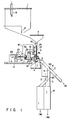
- FIG. 1 is a side view showing the schematic arrangement of a weight selector incorporating a capsule weight measuring apparatus according to this embodiment.
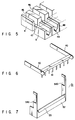
- FIG. 3 is a perspective view showing the main parts of the capsule weight measuring apparatus in FIG. 1.
- a first hopper 1 containing a large number of capsules is provided in the upper portion of the housing of the weight selector indicated by the alternately long and short dashed lines in FIG. 3.
- a second hopper 2 having a funnel-like bottom opening and connected to the first hopper 1 is provided in front of and below the first hopper 1.
- a plurality of magazines 3 in which capsule supply paths are formed, as will be described later, are so arranged as to be vertically movable below the funnel-like bottom opening of the second hopper 2.
- a capsule receiving table 4 and weighing tables 5 of a plurality of weighing mechanisms are provided below the magazines 3.
- a guide 7 for guiding capsules to a selector 6 for selecting capsules whose weights are measured is provided in front of and below the weighing tables 5.
- the first hopper 1 includes an upper-limit sensor 8 and a lower-limit sensor 9 for appropriately controlling the number of capsules contained in the first hopper 1.
- a plurality of vertically extending supply paths 10 are formed inside the magazine 3.
- the inner diameter of the supply path 10 is set to be slightly larger than the outer diameter of a predetermined capsule 12 to be weighed so that the capsule 12 enters the supply path 10 in the longitudinal direction.
- an upper end opening 13 of the supply path 10 of the magazine 3 opposes the bottom opening of the second hopper 2.
- the upper end opening 13 is tapered and has diameter larger than the diameter of the central portion of the supply path 10.
- the magazine 3 vertically moves at a predetermined period so as to move forward and backward with respect to the bottom opening of the fixed second hopper 2.
- FIG. 8 is a sectional view showing the state in which the magazine 3 reaches the upper end.
- the upper end opening 13 of the supply path 10 enters and largely rises from the bottom opening of the second hopper 2.
- FIG. 9 is a sectional view showing the state in which the magazine 3 reaches the lower end.
- the upper end opening 13 of the supply path 10 retracts from the bottom opening of the second hopper 2 to the lower end position.
- a communication hole 14 communicating with the outside of the magazine 3 is formed near the upper end opening 13 of the supply path 10.
- a nozzle 16 as an upper air blow mechanism for applying pressurized air, supplied from the outside through a pipe 15, to the supply path 10 through the communication hole 14 is disposed near the lower end of the second hopper 2.
- the magazine 3 moves up and down. Therefore, as shown in FIG. 8, at the timing the magazine 3 reaches the upper end, the nozzle 16 and the communication hole 14 oppose each other, and, where necessary as will be described later, pressurized air can be injected from the nozzle 16 into the supply path 10 at this timing.
- the nozzle 16 and the communication hole 14 are thus provided, when the upper end opening 13 of the supply nozzle 10 clogs with the capsules 12 as shown in FIG. 10, the nozzle 16 applies pressurized air into the supply path 10. Consequently, the capsules 12 in the upper end opening 13 can be scattered into the second hopper 2.
- a vertical moving mechanism of the magazine 3 and a transfer mechanism for transferring the capsule 12 from the lower end of the supply path 10 of the magazine 3 will be described below with reference to FIGS. 1 and 2.
- a central portion of an L-shaped arm 19 is axially supported to be pivotal about a shaft 20 of a fixed base plate 18 fixed to a frame 17 of the weight selector housing.
- crank shaft 22 is pivotally supported by a shaft 21 at the lower end of the L-shaped arm 19.
- crank shaft 22 is axially supported by one portion on the circumference of a rotary disk 23 pivotally supported by the fixed base plate 18.
- This rotary disk 23 is rotated via a belt 23a by a driving motor 24 mounted on the frame 17.
- a shaft 26 provided at the other end of the L-shaped arm 19 is locked with a slight margin in a hole formed in a support plate 25 fixed to the magazine 3.
- the L-shaped arm 19 pivots clockwise and counterclockwise about the shaft 20, and the support plate 25 locked by the shaft 26 at the other end of the L-shaped arm 19 moves up and down along a guide 27.
- the magazine 3 also moves up and down.
- pivoting members 28 are axially supported by a common shaft 29 in a one-to-one correspondence with the support paths 10.
- the common shaft 29 is fixed to the magazine 3 or the support plate 25.
- each stopper 30 closes a lower end opening 31 of the supply path 10, so the capsule 12 does not fall from this lower end opening 31 onto the capsule receiving table 4.
- stopper locking members 32 for selectively locking the pivoting members 28 are pivotally supported by a common shaft 33 fixed to the fixed base plate 18 in a one-to-one correspondence with the supply paths 10.
- a plurality of solenoids 35 for selectively stopping the locking operations by the stopper locking members 32 with respect to the pivoting members 28 are mounted on a support plate 34 fixed to the fixed base plate 18.
- these solenoids 35 constitute a stopper fixing mechanism.
- the stopper locking member 32 abuts against the pivoting member 28, as shown in FIG. 2, when the magazine 3 moves down to the lower end position, and makes this pivoting member 28 pivot clockwise against the coil spring.
- the stopper 30 comes off the position of the lower end opening 31 of the supply path 10, and only the lowermost one of a number of capsules 12 staying in the supply path 10 falls from the lower end opening 31 onto the capsule receiving table 4.
- grooves 46 having a V-shaped bottom are formed at positions where the grooves 46 oppose the lower end openings 31.
- a fine groove 47 is formed in the lowest end of each groove 46.
- the capsule 12 falls from the lower end opening 31 of each supply path 10 of the magazine 3 into the groove 46 of the capsule receiving table 4.
- the separate weighing tables 5 are provided in the extending direction of the grooves 46 of the capsule receiving table 4 in a one-to-one correspondence with these grooves 46.
- a groove 48 and a fine groove 49 having the same sectional shape as the groove 46 formed in the capsule receiving table 4 are formed in the upper surface of each weighing table 5 so as to oppose and communicate with the groove 46.
- One capsule 12 is placed in the groove 48, and the weight of this capsule 12 is measured.
- a pusher 37 whose moving direction is regulated in a horizontal direction by a slide guide 36 which moves parallel to the frame 17 is incorporated.
- a plurality of tips 38 are formed at one end of the pusher 37 on the side of the magazine 3. Each tip 38 lays the capsule 12, falling from the lower end opening 31 of the supply path 10 into the groove 46 formed in the capsule receiving table 4, in the direction of the groove 46.
- Each of discharge members 40 for pushing the measured capsules 12 from the weighing tables 5 is pivotally attached to a shaft 39 provided in a middle position of the pusher 37.
- discharge bars 41 for discharging the measured capsules 12 from the grooves 48 of the weighing tables 5 to the guide 7 of the selector 6 extend downward from the other end (distal end) of each discharge member 40.
- the range of the pivot angle of the discharge members 40 is regulated by a stopper pin 42 formed on the fixed base plate 18.
- a shaft 43 provided near the shaft 39 of the discharge members 40 and a shaft 45 provided at the lower end of the L-shaped arm 19 are connected by a connecting plate 44.
- the discharge members 40 are leveled.
- the pivoting angle of the discharge members 40 is regulated by the stopper pin 42 formed on the fixed base plate 18. Therefore, when the connecting plate 44 further moves toward the magazine 3, the pusher 37 and the discharge members 40 move in the direction of the magazine 3 while the discharge members 40 are kept leveled.
- the tips 38 of the pusher 37 push the upper end portions of the capsules 12, falling into the grooves 46 formed in the capsule receiving table 4, in the direction of the grooves 46, thereby laying the capsules 12 along the grooves 46. Also, step portions below the tips 38 push the capsules 12 thus laid into the grooves 48 of the weighing tables 5.
- the discharge bars 41 at the ends of the discharge members 40 discharge the measured capsules 12 remaining in the grooves 48 of the weighing tables 5 to the guide 7 of the selector 6.
- the pusher 37 constitutes a push transfer mechanism which, in synchronism with the vertical motion of the magazine 3, lays the capsules 12 falling from the lower end openings 31 of the supply paths 10 into the grooves 46 of the capsule receiving table 4 and pushes the capsules 21 in the extending direction of the grooves.
- the discharge members 40 constitute a discharge mechanism for discharging the capsules 12 weighed by the weighing mechanism.
- a nozzle 50 is provided in a position where the nozzle 50 opposes the fine groove 47 formed in the bottom of each groove 46 of the capsule receiving table 4 and opposes the fine groove 49 formed in the bottom of the groove 48 of each weighing table 5.
- This nozzle 50 functions as a lower air blow mechanism for applying pressurized air to these fine grooves 47 and 49.
- a vertically movable shutter 51 is provided between the weighing tables 5 and the guide 7 of the selector 6.
- an inclined plate 53 for smoothly guiding the capsules 12 to the guide 7 is formed at the upper end of a shutter plate 52 of the shutter 51.
- Engaging portions 54a and 54b are formed in side plates of the shutter 51.
- the groove 48 of each weighing table 5 does not oppose the shutter plate 52, i.e., the front end of the groove 48 of each weighing table 5 is open.
- the L-shaped arm 19 pivots clockwise and counterclockwise about the shaft 20.
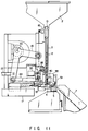
- the state of the apparatus changes from FIG. 2 to FIGS. 11 through 15.
- the pusher 37 starts advancing, and the discharge bars 41 at the ends of the discharge members 40 start pivoting downward.
- the discharge bars 41 at the ends of the discharge members 40 discharge the measured capsules 12 remaining in the grooves 48 of the weighing tables 5 to the guide 7 of the selector 6.
- the shutter plate 52 of the shutter 51 positioned between the weighing tables 5 and the guide 7 rises to the position where the shutter plate 52 opposes the grooves 48 of the weighing tables 5.
- the shutter plate 52 prevents the capsules 12 from springing out of the grooves 48 of the weighing tables 5.
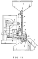
- the stoppers 30 keep closing the lower end openings 31 of the supply paths 10 of the magazine 3.
- the tips 38 of the pusher 37 are positioned behind the supply paths 10 of the magazine 3, and the pivoting members 28 abut against the stopper locking members 32. Consequently, the stoppers 30 come off the lower end openings 31 of the supply paths 10 of the magazine 3, opening the lower end openings 31.
- the capsules 12 contained in the second hopper 2 fall through the supply paths 10 of the vertically moving magazine 3.
- each stopper 30 opens to drop only one capsule 12 into the groove 46 of the capsule receiving table 4 below the magazine 3.
- the pusher 37 moves forward to lay the capsules 12, dropped into the grooves 46, into a lying state.
- the capsules 12 are pushed in the extending direction of the grooves 46 and transferred, while being kept in the lying state, into the grooves 48 of the adjacent weighing tables 5.
- the capsules 12 whose weights are measured by the weighing tables 5 are discharged to the guide 7 by the discharge members 40.
- the grooves 46 and 48 communicating with each other are formed in the capsule receiving table 4 and the weighing tables 5. Therefore, when the pusher 37 lays the capsules 12, these capsules 12 fall such that their longitudinal direction is consistent with the extending direction of the grooves 46.
- the capsules 12 falling in the extending direction of the grooves can be easily and reliably pushed to the weighing tables 5 by the pusher 37.
- the shutter plate 52 of the shutter 51 positioned between the weighing tables 5 and the guide 7 has ascended to the position where the shutter plate 52 opposes the grooves 48 of the weighing tables 5.
- the shutter plate 52 prevents the capsules 12 from springing out of the grooves 48 of the weighing tables 5 toward the guide 7.
- the rotating speed of the driving motor 24 is raised to raise the moving velocity of the capsules 12 and thereby increase the measurement rate for the capsules 12 in the capsule weight measuring apparatus, the weight of each capsule 12 can be accurately measured.
- the weights of a maximum of 1,250 capsules 12 can be measured per one minute.
- the pivoting position of the stopper locking members 32 is fixed, and the solenoids 35 as a stopper fixing mechanism for fixing the stoppers 30 to the lower end openings 31 are provided in a one-to-one correspondence with the supply paths 10 of the magazine 3.
- the adjustment or maintenance inspection, for example, of the weighing machines can be executed while no capsules 12 are loaded onto the weighing tables 5 by stopping the supply of the capsules 12.
- the solenoids 35 are provided in a one-to-one correspondence with the supply paths 10, it is possible to stop only the supply of the capsules 12 from the supply path 10 corresponding to the weighing table 5 of an abnormal weighing machine, while the other normal weighing machines are kept in operation.
- the communication hole 14 communicating with each supply path 10 is formed outside the magazine 3.
- the nozzle 16 for applying pressurized air to each supply path 10 through the communication hole 14 when the magazine 3 reaches the upper end is fixedly disposed, normally in a non-contact state, in a position where the nozzle 16 opposes the communication hole 14.
- a specific weighing table 5 does not output a measurement signal of the capsule 12 within a predetermined time even though a large number of the capsules 12 exist in the second hopper 2, it is determined that the upper end opening 13 clogs with the capsules 12. Accordingly, the nozzle 16 corresponding to the supply path 10 which corresponds to that weighing table 5 is automatically driven for a predetermined time. This automatically eliminates the clogging with the capsules 12.
- the nozzle 50 for applying pressurized air to the fine groove 47 formed in the bottom of each groove 46 of the capsule receiving table 4 and to the fine groove 49 formed in the bottom of the groove 48 of each weighing table 5 is provided in a position where the nozzle 50 opposes these fine grooves 47 and 49.
- a determination controller such as a CPU closes first and second gates 6a and 6b (FIG. 1) to a position A or B and a position C or D, respectively, on the basis of a measurement signal from each weighing table 5, thereby selectively supplying the measured capsule 12 to an OK passage, a -NG passage, or a +NG passage.
- the CPU closes the first gate 6a to the position B to supply the measured capsule 12 to the OK passage.
- the position of the second gate 6b can be left undetermined because the passage to the second gate 6b is closed.
- the CPU closes the first gate 6a to the position A and the second gate 6b to the position C, thereby supplying the measured capsule 12 to the -NG passage.
- the CPU closes the first gate 6a to the position A and the second gate 6b to the position D, thereby supplying the measured capsule 12 to the +NG passage.
- the grooves as a first guide mechanism for receiving capsules falling from the supply paths formed in the magazine as a capsule supply mechanism are formed in the capsule receiving table.
- the grooves as a second guide mechanism opposing and communicating with the grooves of the capsule receiving table are formed in the weighing tables. Accordingly, without uprightly dropping capsules onto weighing tables as in conventional techniques, capsules laid into a lying state by the pusher as a transfer mechanism are pushed from the grooves of the capsule receiving table by sliding the capsules along their longitudinal direction, and transferred to the grooves of the weighing tables.
- capsules in a stable lying state are transferred onto the weighing tables. Accordingly, capsules are not dropped and transferred in an unstable upright state as in conventional techniques, and no vibrations are produced on the weighing tables. As a consequence, it is possible to rapidly measure the weight of each capsule while maintaining a high measurement accuracy.
- the capsule weight measuring apparatus of the present invention the shutter which operates in synchronism with the magazine is disposed before the weighing tables. Therefore, even when capsules falling into the grooves of the capsule receiving table are rapidly pushed to the weighing tables, these capsules are prevented from springing out of the weighing tables. This further increases the rate at which the weight of each capsule is measured.
- the stopper fixing mechanism is incorporated to stop, where necessary, the supply of capsules from the supply paths of the magazine to the weighing tables. This improves the work efficiency of inspection and maintenance of the weighing tables.
- the communication hole communicating with the outside is formed in each supply path of the magazine.
- the nozzle provided in a position where it opposes this communication hole when the magazine comes to the upper end position applies pressurized air to the supply path. Consequently, the clogging of the upper end opening of the supply path with capsules can be easily eliminated.
- this upper air blow mechanism eliminates the need to always connect an air blow conduit directly to a vertically moving supply pipe as in conventional techniques. This simplifies the structure and handling of the piping for the nozzle.
Applications Claiming Priority (3)
| Application Number | Priority Date | Filing Date | Title |
|---|---|---|---|
| JP20596696 | 1996-08-05 | ||
| JP20596696A JP3343480B2 (ja) | 1996-08-05 | 1996-08-05 | カプセル重量測定装置 |
| JP205966/96 | 1996-08-05 |
Publications (3)
| Publication Number | Publication Date |
|---|---|
| EP0823619A2 true EP0823619A2 (de) | 1998-02-11 |
| EP0823619A3 EP0823619A3 (de) | 1998-11-04 |
| EP0823619B1 EP0823619B1 (de) | 2003-04-16 |
Family
ID=16515670
Family Applications (1)
| Application Number | Title | Priority Date | Filing Date |
|---|---|---|---|
| EP97113052A Expired - Lifetime EP0823619B1 (de) | 1996-08-05 | 1997-07-29 | Gewichtsmessgerät von Kapseln |
Country Status (4)
| Country | Link |
|---|---|
| US (1) | US5852259A (de) |
| EP (1) | EP0823619B1 (de) |
| JP (1) | JP3343480B2 (de) |
| DE (1) | DE69720886T2 (de) |
Cited By (5)
| Publication number | Priority date | Publication date | Assignee | Title |
|---|---|---|---|---|
| DE19819316A1 (de) * | 1998-04-30 | 1999-11-04 | Bosch Gmbh Robert | Wiegeeinrichtung für pharmazeutische Erzeugnisse wie Hartgelatinekapseln, Tabletten oder dgl. |
| DE102005018708A1 (de) * | 2005-04-21 | 2006-11-02 | Wipotec Wiege- Und Positioniersysteme Gmbh | Wägevorrichtung, insbesondere Mehrspur-Wägevorrichtung |
| DE102009060234A1 (de) * | 2009-12-23 | 2011-06-30 | Bizerba GmbH & Co KG, 72336 | Mehrspurwaage |
| DE102009060291A1 (de) * | 2009-12-23 | 2011-06-30 | Bizerba GmbH & Co KG, 72336 | Wägevorrichtung |
| CN109489780A (zh) * | 2018-11-30 | 2019-03-19 | 黑龙江迪尔制药机械有限责任公司 | 一种逐粒送丸称重机构及药丸逐粒自动称重装置 |
Families Citing this family (43)
| Publication number | Priority date | Publication date | Assignee | Title |
|---|---|---|---|---|
| IT1285463B1 (it) * | 1996-02-21 | 1998-06-08 | Ima Spa | Apparato per la pesatura automatica, continua, rapida e precisa di prodotti di piccole dimensioni, particolarmente di capsule di gelatina |
| DE19819395C1 (de) * | 1998-04-30 | 1999-10-28 | Bosch Gmbh Robert | Vorrichtung zum Wiegen von Hartgelatinekapseln o. dgl. |
| AU1617101A (en) | 1999-11-15 | 2001-05-30 | Walgreens Co. | Apparatus and method for accessing pharmacy information and ordering prescriptions |
| FR2807847B1 (fr) * | 2000-04-12 | 2002-11-22 | St Microelectronics Sa | Regulateur lineaire a faible surtension en regime transitoire |
| US8321236B2 (en) * | 2002-02-01 | 2012-11-27 | Walgreen Co. | Method and apparatus for prescription processing |
| US20030179287A1 (en) * | 2002-03-22 | 2003-09-25 | Dejan Kozic | System and method for providing pharmaceutical services to a plurality of remote sites from a central site |
| US20040172289A1 (en) * | 2003-02-28 | 2004-09-02 | Dejan Kozic | Method and system for remotely verifying a prescription |
| US7071706B2 (en) * | 2003-06-03 | 2006-07-04 | Boehringer Ingelheim International, Gmbh | Measuring device for rapid non-destructive measurement of the contents of capsules |
| EP1484586A1 (de) * | 2003-06-03 | 2004-12-08 | BOEHRINGER INGELHEIM PHARMA GMBH & CO. KG | Messeinrichtung zur zerstörungsfreien Bestimmung der Einwaage in Kapseln |
| DE10351212A1 (de) * | 2003-11-03 | 2005-06-02 | Robert Bosch Gmbh | Maschine zum Füllen und Verschließen von zweiteiligen Kapseln |
| US7801642B2 (en) | 2004-08-18 | 2010-09-21 | Walgreen Co. | System and method for checking the accuracy of a prescription fill |
| US7523594B2 (en) * | 2005-08-24 | 2009-04-28 | Greenwald Technologies, Llc. | Systems and methods for packaging solid pharmaceutical and/or nutraceutical products and automatically arranging the solid pharmaceutical and nutraceutical products in a linear transmission system |
| US7734478B2 (en) | 2005-10-18 | 2010-06-08 | Walgreen Co. | Method and apparatus for inter-pharmacy workload balancing using resource function assignments |
| US7765108B2 (en) | 2005-10-18 | 2010-07-27 | Walgreen Co. | Method and apparatus for inter-pharmacy workload balancing |
| US8175891B2 (en) | 2005-10-18 | 2012-05-08 | Walgreen Co. | System for separating and distributing pharmacy order processing for compound medication |
| US8666780B2 (en) * | 2005-10-18 | 2014-03-04 | Walgreen Co. | System for separating and distributing pharmacy order processing |
| US8315887B2 (en) | 2005-10-18 | 2012-11-20 | Walgreen Co. | System for separating and distributing pharmacy order processing for specialty medication |
| US8311891B2 (en) | 2005-10-18 | 2012-11-13 | Walgreen Co. | System for separating and distributing pharmacy order processing for medication payments |
| DE102005057393A1 (de) * | 2005-11-30 | 2007-05-31 | Robert Bosch Gmbh | Wiegevorrichtung einer Verpackungsmaschine |
| DE102005060039B4 (de) * | 2005-12-15 | 2007-08-30 | Wipotec Wiege- Und Positioniersysteme Gmbh | Wägestation mit Förderelement |
| CN101210840B (zh) * | 2006-12-30 | 2011-08-03 | 上海恒谊制药设备有限公司 | 胶囊充填量检测机及其应用 |
| KR100833607B1 (ko) * | 2007-03-02 | 2008-05-30 | 주식회사 세종파마텍 | 트랜스퍼 피드 및 그 트랜스퍼 피드를 구비한 캡슐검수장치 |
| US8775198B2 (en) | 2007-07-25 | 2014-07-08 | Walgreen Co. | System and method for performing a remote verification of a pharmacy fill utilizing an image to image comparison |
| DE212008000123U1 (de) * | 2008-07-09 | 2011-04-28 | Shanghai Hengyi Pharmaceutical Equipment Co., Ltd. | Vorrichtung zum schnellen Wiegen von Kapseln |
| US8145501B1 (en) | 2008-10-09 | 2012-03-27 | Walgreen Co. | System and method for performing pharmacy product filling using non-registered pharmacists |
| US7941325B2 (en) * | 2008-11-14 | 2011-05-10 | Walgreen Co. | System and method of using a non-retail central filling facility to process pharmacy product prescriptions in a pharmacy retail network |
| IT1394886B1 (it) * | 2009-07-17 | 2012-07-20 | Sacmi | Sistema di ispezione e pesatura di oggetti, in particolare preforme. |
| KR101108076B1 (ko) | 2010-05-20 | 2012-01-31 | (주)케이비알 | 자동 포장기 |
| IT1401415B1 (it) * | 2010-08-20 | 2013-07-26 | Ima Spa | Sistema e metodo per pesare articoli |
| KR101327831B1 (ko) * | 2011-09-28 | 2013-11-11 | 김종삼 | 자동 캡슐 중량 선별장치 |
| US10427809B2 (en) | 2012-06-01 | 2019-10-01 | Rxsafe Llc | Pharmacy packaging system |
| US10427810B2 (en) * | 2012-06-01 | 2019-10-01 | Rxsafe Llc | Pharmacy packaging system |
| FR3017377B1 (fr) * | 2014-02-12 | 2017-01-13 | Stiplastics | Dispositif de comptage et de distribution d'objets |
| JP6227437B2 (ja) * | 2014-02-17 | 2017-11-08 | アンリツインフィビス株式会社 | 重量測定装置 |
| JP6289169B2 (ja) * | 2014-02-28 | 2018-03-07 | アンリツインフィビス株式会社 | 重量測定装置 |
| JP6495120B2 (ja) * | 2015-06-29 | 2019-04-03 | アンリツインフィビス株式会社 | 重量測定装置 |
| EP3339818B1 (de) * | 2016-12-23 | 2019-06-12 | Harro Höfliger Verpackungsmaschinen GmbH | Vorrichtung und verfahren zum wiegen von gefüllten kapseln |
| IT201700123930A1 (it) * | 2017-10-31 | 2019-05-01 | Ima Spa | Macchina riempitrice. |
| EP3488841B1 (de) * | 2017-11-24 | 2020-03-18 | Harro Höfliger Verpackungsmaschinen GmbH | Kapselwiegeeinrichtung und kapselfülleinrichtung mit einer solchen kapselwiegeeinrichtung |
| CN108820377B (zh) * | 2018-05-10 | 2023-11-03 | 苏州双荣橡塑有限公司 | 一种包胶轮的自动计数装置 |
| CN109396055A (zh) * | 2018-12-19 | 2019-03-01 | 贵州大学 | 一种胶囊称重台 |
| CN112190479A (zh) * | 2020-05-07 | 2021-01-08 | 星德科包装技术(杭州)有限公司 | 供给装置、匣盒装置、分拣装置、分拣站及胶囊填充机 |
| CN116571458B (zh) * | 2023-06-12 | 2024-03-15 | 苏州漫多罗精密机电科技有限公司 | 一种多通道胶囊重量分选设备 |
Citations (3)
| Publication number | Priority date | Publication date | Assignee | Title |
|---|---|---|---|---|
| US4223751A (en) * | 1979-03-26 | 1980-09-23 | Modern Controls, Inc. | High speed capacitance apparatus for classifying pharmaceutical capsules |
| EP0685714A1 (de) * | 1994-06-03 | 1995-12-06 | Harro Höfliger Verpackungsmaschinen GmbH | Vorrichtung zum Wiegen von Hartgelatinekapseln |
| WO1996020390A1 (en) * | 1994-12-23 | 1996-07-04 | I.M.A. Industria Macchine Automatiche S.P.A. | Method and apparatus for checking the weight of small articles |
Family Cites Families (7)
| Publication number | Priority date | Publication date | Assignee | Title |
|---|---|---|---|---|
| US3775941A (en) * | 1972-02-10 | 1973-12-04 | Pennwalt Corp | Article packaging machine |
| JPS5239961A (en) * | 1975-09-24 | 1977-03-28 | Shinko Fuaudoraa Kk | Nitrating method using absorbent |
| IT1069355B (it) * | 1976-03-05 | 1985-03-25 | Zanasi Nigris Spa | Perfezionamenti particolarmente nelle macchine automatiche per il confezionamento di dosi di prodotto medicinale entro capsule di gelatina |
| DE2719142A1 (de) * | 1977-04-29 | 1978-11-09 | Bosch Gmbh Robert | Verfahren und vorrichtung zum ausscheiden von beschaedigten hartgelatinekapseln |
| US4191294A (en) * | 1977-12-15 | 1980-03-04 | American Cyanamid Company | Empty capsule ejector |
| JPS5733353A (en) * | 1980-08-06 | 1982-02-23 | Furonto Sangyo Kk | Tester for physical properties of solid agent |
| IT1264247B1 (it) * | 1993-10-22 | 1996-09-23 | Mg 2 Spa | Metodo per la determinazione del peso di prodotti farmaceutici e macchina per la dosatura di prodotti farmaceutici utilizzante |
-
1996
- 1996-08-05 JP JP20596696A patent/JP3343480B2/ja not_active Expired - Lifetime
-
1997
- 1997-07-23 US US08/898,971 patent/US5852259A/en not_active Expired - Lifetime
- 1997-07-29 EP EP97113052A patent/EP0823619B1/de not_active Expired - Lifetime
- 1997-07-29 DE DE69720886T patent/DE69720886T2/de not_active Expired - Lifetime
Patent Citations (3)
| Publication number | Priority date | Publication date | Assignee | Title |
|---|---|---|---|---|
| US4223751A (en) * | 1979-03-26 | 1980-09-23 | Modern Controls, Inc. | High speed capacitance apparatus for classifying pharmaceutical capsules |
| EP0685714A1 (de) * | 1994-06-03 | 1995-12-06 | Harro Höfliger Verpackungsmaschinen GmbH | Vorrichtung zum Wiegen von Hartgelatinekapseln |
| WO1996020390A1 (en) * | 1994-12-23 | 1996-07-04 | I.M.A. Industria Macchine Automatiche S.P.A. | Method and apparatus for checking the weight of small articles |
Cited By (8)
| Publication number | Priority date | Publication date | Assignee | Title |
|---|---|---|---|---|
| DE19819316A1 (de) * | 1998-04-30 | 1999-11-04 | Bosch Gmbh Robert | Wiegeeinrichtung für pharmazeutische Erzeugnisse wie Hartgelatinekapseln, Tabletten oder dgl. |
| DE19819316B4 (de) * | 1998-04-30 | 2007-06-28 | Robert Bosch Gmbh | Wiegeeinrichtung für pharmazeutische Erzeugnisse wie Hartgelatinekapseln, Tabletten oder dgl. |
| DE102005018708A1 (de) * | 2005-04-21 | 2006-11-02 | Wipotec Wiege- Und Positioniersysteme Gmbh | Wägevorrichtung, insbesondere Mehrspur-Wägevorrichtung |
| DE102005018708B4 (de) * | 2005-04-21 | 2007-01-11 | Wipotec Wiege- Und Positioniersysteme Gmbh | Wägevorrichtung, insbesondere Mehrspur-Wägevorrichtung |
| DE102009060234A1 (de) * | 2009-12-23 | 2011-06-30 | Bizerba GmbH & Co KG, 72336 | Mehrspurwaage |
| DE102009060291A1 (de) * | 2009-12-23 | 2011-06-30 | Bizerba GmbH & Co KG, 72336 | Wägevorrichtung |
| EP2343520B1 (de) | 2009-12-23 | 2018-04-18 | Bizerba SE & Co. KG | Mehrspurwaage |
| CN109489780A (zh) * | 2018-11-30 | 2019-03-19 | 黑龙江迪尔制药机械有限责任公司 | 一种逐粒送丸称重机构及药丸逐粒自动称重装置 |
Also Published As
| Publication number | Publication date |
|---|---|
| DE69720886D1 (de) | 2003-05-22 |
| EP0823619A3 (de) | 1998-11-04 |
| JP3343480B2 (ja) | 2002-11-11 |
| US5852259A (en) | 1998-12-22 |
| JPH1048032A (ja) | 1998-02-20 |
| DE69720886T2 (de) | 2004-03-11 |
| EP0823619B1 (de) | 2003-04-16 |
Similar Documents
| Publication | Publication Date | Title |
|---|---|---|
| US5852259A (en) | Capsule weight measuring apparatus | |
| EP0502201B1 (de) | Kombinationswaage mit grosser präzision für einen grossen produktbereich einschliesslich viskoser substanzen | |
| CA2006805C (en) | A capsule charging apparatus | |
| KR100356647B1 (ko) | 젤라틴캡슐과같은소형물품을중량측정하는장치 | |
| EP0999129B1 (de) | Maschine zum Verpacken von Tabletten | |
| US4235066A (en) | Nuclear fuel rod loading apparatus | |
| KR920010793B1 (ko) | 케이싱 공급방법 및 장치 | |
| US4534429A (en) | Combinatorial weighing apparatus | |
| EP1014053B1 (de) | Sortierer nach gewicht | |
| US6877611B2 (en) | Weight sorter | |
| US5796616A (en) | Apparatus for automatically replenishing chips | |
| US4343130A (en) | Continuous movement capsule filling and closing machine, particularly for packaging powder or granulated loose products | |
| WO1989006213A1 (en) | Apparatus for transferring elongated sample tube holders to and from workstations | |
| EP0866004A1 (de) | Vorrichtung zum Ausrichten von Gegenständen | |
| JPH08271327A (ja) | 棒状組合せ計量機 | |
| US5758798A (en) | Parts orientor and method | |
| JP4129997B2 (ja) | 産物準備供給システムのための産物供給装置 | |
| KR0122097B1 (ko) | 약제포장용 정량공급장치 | |
| JP3570518B2 (ja) | カプセル充填物の秤量方法及びカプセル充填機 | |
| JPS59232085A (ja) | 紙巻タバコの検査及び製列装置 | |
| WO1989006206A1 (en) | Method for transferring elongated sample tube holders to and from workstations | |
| JP6289145B2 (ja) | 重量測定装置 | |
| US6112882A (en) | Ampule delivery device | |
| JP2512261Y2 (ja) | チップ状回路部品供給装置 | |
| KR960006764B1 (ko) | 핸들러의 튜브 자동공급장치 |
Legal Events
| Date | Code | Title | Description |
|---|---|---|---|
| PUAI | Public reference made under article 153(3) epc to a published international application that has entered the european phase |
Free format text: ORIGINAL CODE: 0009012 |
|
| 17P | Request for examination filed |
Effective date: 19970729 |
|
| AK | Designated contracting states |
Kind code of ref document: A2 Designated state(s): DE FR GB IT |
|
| PUAL | Search report despatched |
Free format text: ORIGINAL CODE: 0009013 |
|
| AK | Designated contracting states |
Kind code of ref document: A3 Designated state(s): AT BE CH DE DK ES FI FR GB GR IE IT LI LU MC NL PT SE |
|
| AKX | Designation fees paid |
Free format text: DE FR GB IT |
|
| 17Q | First examination report despatched |
Effective date: 20020129 |
|
| GRAH | Despatch of communication of intention to grant a patent |
Free format text: ORIGINAL CODE: EPIDOS IGRA |
|
| GRAH | Despatch of communication of intention to grant a patent |
Free format text: ORIGINAL CODE: EPIDOS IGRA |
|
| GRAA | (expected) grant |
Free format text: ORIGINAL CODE: 0009210 |
|
| AK | Designated contracting states |
Designated state(s): DE FR GB IT |
|
| REG | Reference to a national code |
Ref country code: GB Ref legal event code: FG4D |
|
| RAP2 | Party data changed (patent owner data changed or rights of a patent transferred) |
Owner name: ANRITSU INDUSTRIAL SOLUTIONS CO.,LTD. |
|
| REF | Corresponds to: |
Ref document number: 69720886 Country of ref document: DE Date of ref document: 20030522 Kind code of ref document: P |
|
| ET | Fr: translation filed | ||
| PLBE | No opposition filed within time limit |
Free format text: ORIGINAL CODE: 0009261 |
|
| STAA | Information on the status of an ep patent application or granted ep patent |
Free format text: STATUS: NO OPPOSITION FILED WITHIN TIME LIMIT |
|
| 26N | No opposition filed |
Effective date: 20040119 |
|
| REG | Reference to a national code |
Ref country code: FR Ref legal event code: PLFP Year of fee payment: 20 |
|
| PGFP | Annual fee paid to national office [announced via postgrant information from national office to epo] |
Ref country code: FR Payment date: 20160613 Year of fee payment: 20 |
|
| PGFP | Annual fee paid to national office [announced via postgrant information from national office to epo] |
Ref country code: DE Payment date: 20160726 Year of fee payment: 20 Ref country code: GB Payment date: 20160727 Year of fee payment: 20 Ref country code: IT Payment date: 20160720 Year of fee payment: 20 |
|
| REG | Reference to a national code |
Ref country code: DE Ref legal event code: R071 Ref document number: 69720886 Country of ref document: DE |
|
| REG | Reference to a national code |
Ref country code: GB Ref legal event code: PE20 Expiry date: 20170728 |
|
| PG25 | Lapsed in a contracting state [announced via postgrant information from national office to epo] |
Ref country code: GB Free format text: LAPSE BECAUSE OF EXPIRATION OF PROTECTION Effective date: 20170728 |