EP0819964B1 - Kontrolle einer Mikroskopblende - Google Patents
Kontrolle einer Mikroskopblende Download PDFInfo
- Publication number
- EP0819964B1 EP0819964B1 EP96305199A EP96305199A EP0819964B1 EP 0819964 B1 EP0819964 B1 EP 0819964B1 EP 96305199 A EP96305199 A EP 96305199A EP 96305199 A EP96305199 A EP 96305199A EP 0819964 B1 EP0819964 B1 EP 0819964B1
- Authority
- EP
- European Patent Office
- Prior art keywords
- aperture
- stage
- sample
- microscope
- interest
- Prior art date
- Legal status (The legal status is an assumption and is not a legal conclusion. Google has not performed a legal analysis and makes no representation as to the accuracy of the status listed.)
- Expired - Lifetime
Links
Images


Classifications
-
- G—PHYSICS
- G02—OPTICS
- G02B—OPTICAL ELEMENTS, SYSTEMS OR APPARATUS
- G02B21/00—Microscopes
- G02B21/24—Base structure
- G02B21/26—Stages; Adjusting means therefor
-
- G—PHYSICS
- G02—OPTICS
- G02B—OPTICAL ELEMENTS, SYSTEMS OR APPARATUS
- G02B21/00—Microscopes
- G02B21/0004—Microscopes specially adapted for specific applications
- G02B21/0016—Technical microscopes, e.g. for inspection or measuring in industrial production processes
-
- G—PHYSICS
- G02—OPTICS
- G02B—OPTICAL ELEMENTS, SYSTEMS OR APPARATUS
- G02B21/00—Microscopes
- G02B21/36—Microscopes arranged for photographic purposes or projection purposes or digital imaging or video purposes including associated control and data processing arrangements
- G02B21/365—Control or image processing arrangements for digital or video microscopes
Definitions
- This invention relates to the control of microscopes with movable stages.
- the invention has particular application to the control of a microscope which is used in spectroscopy such as IR spectroscopy.
- a microscope which can operate in conjunction with a spectrophotometer. Such apparatus are used to obtain infrared spectra of samples.
- a known microscope is the Perkin-Elmer FT-IR microscope which is described for example in an article by D.W. Shearing, E.F. Young and T.P. Byron entitled “An FT-IR microscope", published in American Laboratory, November 1990.
- Such a microscope includes a movable stage on which a sample to be investigated can be mounted. The microscope permits both visible observation of the sample and analysis of the sample by infrared radiation, either in a transmitting mode or a reflectance mode.
- the microscope also includes a video camera which can be used in conjunction with the visible viewing means in order to generate a video image of the sample for display on the display means of a computer, and a variable aperture.
- the microscope can be used in conjunction with a spectrophotometer such as a Perkin-Elmer System 2000 FT-IR spectrophotometer.
- a spectrophotometer such as a Perkin-Elmer System 2000 FT-IR spectrophotometer.
- This instrument can receive infrared radiation either transmitted via the sample or reflected from the sample and provide an output indicating the spectrum of the sample.
- the stage of the microscope is movable so that in an initial step it can be moved in an X-Y plane to appropriately locate the sample so that analysis of a selected part of the sample can be achieved.
- a first aspect of the invention described in European Patent Application No. 95301428.9 concerned a method of controlling a motor driven stage of a microscope which has a video camera for viewing a sample on the stage, said method comprising creating on a display means of a computer coupled to the video camera an image of the sample, creating and superimposing on said image one or more graphical markers, using said marker or markers to create coordinate data identifying positions of interest on said sample and using said coordinate data subsequently to control the positioning of said stage.
- a second aspect of that invention concerned'a method of controlling a motor driven stage of a microscope which has a video camera for viewing a sample on said stage and an associated computer and display means for displaying a video image of an area viewed by said camera, said method comprising creating on said display means an image of an area of interest on said sample, storing data representative of said image, adjusting the position of said stage to identify another area of said sample and storing data representing that image, repeating said steps for a selected number of areas of said sample, combining said data to create an image of a larger area of said sample which is made up of said individual areas of interest, creating and superimposing on said larger area image one or more graphical markers, using said marker or markers to create coordinate data identifying positions on said sample, and subsequently using said coordinate data to control the positioning of said stage.
- a third aspect of that invention concerned a system for controlling a motor driven stage of a microscope which has a video camera for viewing a sample on the stage, said system including a display means, and a computer for controlling said display means to create on said display an image of a sample on its microscope stage, said computer being arranged to create and superimpose on said image one or more graphical markers which can be used to create coordinate data identifying positions of interest which are used subsequently to position the stage for analysis of the sample.
- a fourth aspect of that invention concerned a system for controlling a motor driven stage of a microscope which has a video camera for viewing a sample on the stage, said system including a display means and a computer for controlling the display to create on said display an image of an area of a sample on the microscope stage, said computer being arranged to store data representative of an image of the viewed area, to move the stage to another area and store data representative of that area, to repeat these steps for a selected number of areas and to combine the stored data to provide an image of the sample which is larger than the individual areas, said computer also being arranged to come to be displayed and superimposed on the larger area image one or more graphical members which are used to create coordinate data identifying positions of interest on the sample which can be stored and used subsequently to position the stage for analysis of the sample.
- Microscopes of the above described type include an aperture which can be adjusted to define a boundary around the area of interest to be scanned. In conventional microscopes this adjustment is carried out manually.
- EP-A-0453239 describes an optical microscope which has a plurality of objective lenses with different magnification. An image of a specimen can be viewed on a display monitor a desired region for viewing is denoted. The necessary magnification to view that region is calculated and the objective lens appropriate to that magnification is selected to view the region. The stage of the microscope is adjusted automatically for alignment with the selected lens.
- a system for acquiring IR-data according to claim 1 including an aperture.
- the aperture assembly may be arranged to provide. a rectangular or square aperture.
- the aperture may be defined by four movable blades. Each blade may have an inner edge defining a side of the aperture and each blade is movable in a direction perpendicular to that edge.
- Each blade may have an associated motor which is operable in response to control signals from the computer to cause movement of its associated blade to a desired position.
- the microscope assembly can be mounted so that it is rotatable to thereby provide for different aperture orientations.
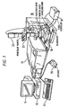
- FIG. 1 A basic arrangement is illustrated in Figure 1 of the drawings. It comprises a microscope (10), a spectrophotometer (11), a computer (12) with a display means (14), a keyboard (17) and joystick (19).
- the microscope includes a movable stage (16) which can be driven in X and Y directions by means of a stage controller (18).
- the microscope also includes viewing means in the form of a microscope viewer (20) for enabling the sample on the stage (16) to be viewed prior to an analysis step and also includes a video camera (22) which can be used to generate a video image of the sample stage.
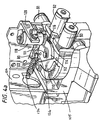
- the microscope (10) can be an FT-IR microscope of the type manufactured by Perkin-Elmer Corporation. Such a microscope has a basic structure which is illustrated in Figure 2 of the drawings.
- the microscope includes the optical microscope (20), a view/IR mirror (24), a remote aperture (26), a transmittance/reflectance mirror (28), an objective Cassegrain lens assembly (27) and a condenser Cassegrain lens assembly (29) with the sample position (30) being located therebetween.
- the drivable stage (16) is located at the sample position.
- the microscope includes a toroid coupling optic (32) which is used to direct radiation towards the sample.
- a detector (36) of the MCT type which can provide data in response to received infrared radiation which is fed to the spectrophotometer for analysis. It is not necessary for the purposes of the present invention to describe the microscope in any more detail since its function will be apparent to those skilled in the art. A fuller description can be found in the manual of The Perkin-Elmer FT-IR microscope and also in the previously referred to article entitled "An FT-IR microscope” published in American Laboratory of November 1990.
- a sample is placed upon the movable stage (16) and the first step is to position the sample prior to analysing it by irradiating it with infrared radiation.
- the sample is positioned by viewing it either optically through the microscope (20) or on the display means (14) using the video camera (22), or both. Once the stage has been positioned appropriately, then a selected area of the sample can be analysed by obtaining an infrared spectrum.
- European Patent Application No. 95301428.9 we describe a technique for identifying areas of interest on the sample using the display means (14) and the subsequent control of the stage during an analysis step to enable those areas of interest to be analysed automatically.
- FIG. 3 the video camera is shown at (22) and operates in conjunction with the microscope viewer which is illustrated at (20).
- the video camera is connected to a circuit board (42) of the computer (12), that circuit board providing the computer (12) with the capability of controlling the display means to display a video image of the movable stage (16).
- the circuit board (42) is a commercially available board known as a frame grabbing card.
- Associated with the computer is the keyboard (17) and a pointer control, typically a mouse, (46).
- the motorised stage is shown at (16) and operates in conjunction with stage control electronics (18) which are coupled to the computer (12).
- the joystick (19) enables an operator to manually control movement of the movable stage (16).
- the stage (16) includes motors (51, 52) for driving the stage in an X-Y plane.
- the microscope includes an aperture assembly (26).
- the aperture assembly includes a plurality of blades which can be moved to define an aperture of a selected size.
- the blades are driven by associated motors (54) which can be energised by signals from drive circuitry (55) in response to control data from the computer (12).
- the apertures assembly is shown in more detail in Figure 4.
- the assembly comprises a pair of upright plates (80, 81) which extend at right angles to each other and to which is attached a support housing (83) for aperture blades.
- the housing (83) supports four aperture blades (84, 85, 86, and 87) centrally thereof.
- Each blade is independently movable toward or away from the centre of the assembly.
- blades (84, 86) can be moved toward or away from each other and the blades (85, 87) can also be moved toward or away from each other along a direction orthogonal to the direction and movement of the blades (84, 86).
- Drive to move the blades is provided by four motors (90, 91, 92, 93) which are secured as shown to the plates (80, 81).
- Motor (90) drives the blade (84) via gearing on its output shaft and a rack and pinion coupling (96), motor (91) drives blade (87) via gearing on its output shaft and a rack and pinion coupling (97), motor (92) drives blade (85) via gearing on its output shaft and a rack and pinion coupling (98) and motor (93) drives blade (86) via gearing on its output shaft and a rack and pinion coupling (99).
- each plate can be moved independently and energising signals for the motors to effect the independent movement are applied from the drive circuitry (55) under the control of the software operating on computer (12).
- Figure 4a illustrates the way in which the aperture assembly is mounted in the microscope so as to be rotatable about an upright axis of the microscope.
- the aperture assembly is carried on a shelf (105) which is secured to the microscope chassis (106).
- the shelf has one or more ball bearings (not shown) on which the aperture assembly sits, the ball bearings enabling the assembly to move over the shelf surface.
- the aperture assembly includes an upper plate (110) (not shown in Figure 4), which covers the block assembly with the exception of a central region defined by a circular aperture (111) which defines a path for radiation to propagate through the assembly.
- the upper plate (110) has a raised, generally semi circular, portion (112) the outer cylindrical part of which has teeth (114) formed thereon.
- the teeth (114) are engaged by corresponding teeth formed on a gear wheel (116) carried on the end of the output shaft of a motor (118).
- the motor (118) is supported from a bracket (120) fixed integrally with the chassis of the microscope.
- the motor (118) when the motor (118) is energised the rotation of its output shaft is transmitted through the engagement of wheel (116) and teeth (114) to cause the aperture assembly to rotate as a unit about a vertical axis of the microscope.
- the motor is bidirectional so that rotation can be in either sense.
- the orientation of the rectangular aperture defined by the blades (84 to 87) can be rotated through 90°.
- a 90° angle of rotation is sufficient to encompass any orientation of the aperture. This is controlled by the software running on the computer (12).
- a spring (122) extends between an upstanding pin (124) on the upper plate (110) and a projection (126) on the microscope chassis. This is to minimise the effect of backlash in the motor (118).
- the computer (12) is thus one which can operate the Windows operating system.
- the microscope (20) is used to view the sample on the stage and also an image of a portion of the sample is generated on the display means (14) using the video camera (22).
- the aperture defined by the aperture assembly (26) is set to its fully open position so that a full field of view is displayed on the display means (14).
- the stage (16) can be controlled electronically through the controller (18) either by use of the joystick controller (19) or in response to commands generated by the computer (12).
- the video camera (22) samples the image and transmits electronic data to the frame grabbing card (42) of the computer and this data is processed and used to generate a display which is a live video image of the sample.
- the software stored in the computer can superimpose graphical images on the image of the sample. These images include a rectangular outline representing the boundary of an aperture.
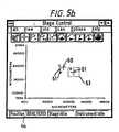
- Figures 5 and 6 show typical displays which can be created.
- the first display is known as a stage control window which enables an operator to adjust the position of the sample stage.
- the display includes markers (60 and 61).
- the marker (60) is a current aperture marker which shows the position on the sample stage of the microscope aperture. It can be used to move the sample stage to different positions without using the joystick.
- the mouse is controlled to move the mouse pointer close to the marker (60).
- the marker (60) is then dragged across the display by moving the mouse position.
- the sample stage is then moved by the stage control electronics (18) to a position corresponding to the repositioned pointer (60). It will be appreciated that the stage can be continuously repositioned using this procedure.
- the display shown in Figure 5 also includes a tool bar facility (62) which comprises a number of icons selectable using the mouse.
- Figure 6 shows an example of a display which is a video image of an area of the sample itself.
- the computer is programmed so that markers can be superimposed on the image of the sample and moved around the sample by means of a pointer control, typically the mouse.
- a pointer control typically the mouse.
- a sample to be analysed is placed on the sample stage of the microscope.
- the sample stage is positioned roughly by moving the stage with the joystick control. This positioning can be carried out visually.
- the two displays are then viewed on the display means simultaneously.
- An operator identifies on the Figure 6 Window an area of interest and using the current stage position marker (60), as described above, moves the stage until that area is centred on the display. Then by using the mouse control buttons the operator marks the area of intent and this produces a marker (61) which does not subsequently move relatively to the area it identifies.
- the display (14) can also display the coordinates of the marked position as indicated by (64) in Figure 5. Those coordinates are also in the computer memory.
- the software then allows an operator to move to another area of interest using the marker (60) as described above and to store in a similar manner data representative of the coordinates of that point of interest. This process can be repeated for as many areas of interest as necessary and coordinate data relating to those areas of interest are stored in the computer memory.
- a marker (61) will appear on the display.
- Figure 5a shows a display with a number of marked points (61).
- Figure 5a also shows how a box can be drawn around the points under the control of a mouse and then that area defined by the box is expanded to create another Window (Figure 5b) with the points displayed on a different scale.
- the software For each position (61) the software allows an operator using the mouse or keyboard to draw around the position (61) a rectangular outline such as that shown at (63) in Figure 5b. This outline represents the boundary of the aperture to be used during a subsequent data acquisition stage. Outlines for each point (61) can be created and data representing the coordinates of these outlines are stored in the computer memory. It will be appreciated that although the aperture (63) is shown in Figure 5b aligned with the X and Y axes of the display it can by manipulation of the mouse or operation of the keyboard be placed in any selected orientation relative to those axes.
- the software for the above operation operates generally as follows.
- the software continuously polls the stage control electronics (18) for the current stage position.
- This software has been precalibrated with camera image size information and is then able to calculate the stage coordinates of any point on the live video image displayed on the display means (14). Once the feature on the sample is visible in the display it can be rapidly centred by pointing at it using the mouse, as explained above.
- the software then calculates the coordinates and causes the stage (16) to move to them.
- the current centre of view is marked with a small computer generated marker. As the stage is moved this marker is repositioned so as to remain with the feature it is marking. This is repeated for each point of interest to be defined.
- the software is used to control automatically the acquisition of analysis data for each of the points of interest during an infrared scanning operation.
- a Window of the type shown in Figure 5c this enables the operator to set up the scan parameters.
- This particular Window has been designed for use with the Paragon 1000 instrument.
- the stage In the acquisition of spectra operation the stage is moved automatically to positions corresponding to the stored coordinate data, i.e. the positions identified by markers (61).
- the computer (12) provides control signals which are fed to the drive circuitry (55) to cause the motors (90, 93) to be energised such that the blades (84 to 87) are positioned to define the pre-set aperture.
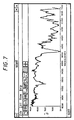
- the motor (118) is energised so that the aperture assembly is rotated to bring it into the selected orientation. It will be appreciated that the present arrangement allows each position from which a spectrum is to be acquired to have its own aperture setting which can be different from the settings of all other positions of interest. At each position the sample is scanned with infrared radiation in the usual manner and a spectrum acquired by the spectrophotometer. These spectra can be displayed on the display means and Figure 7 illustrates an example of such a display.
- the above arrangement provides an operator with an ability to superimpose computer generated graphic markers on a live video image of a sample under investigation, these images being displayed on a display screen of a computer.
- the arrangement also enables an operator to define data representing the position of points of interest on the sample using the computer generated graphic markers and the live video image of the sample. Subsequently the coordinate data can be used during a scanning step to automatically position the sample stage (16) in order to acquire infrared spectral data for each of the points of interest identified by'an operator.
- the markers (61) enable an operator to return the stage easily and'accurately to a position at which a marked point on a sample can be viewed again.
- the ability to graphically define the aperture for each position greatly facilitates aperture setting. Also, once the data relating to the positions of interest has been stored in the computer the subsequent acquisition of IR data can operate automatically under the control of the computer (12) and this substantially increases the efficiency of the system.
Claims (6)
- System zum Erhalten von IR-Daten, welches ein IR-Mikroskop mit einer Motorangetriebenen Plattform (16) einschließt, wobei das Mikroskop eine Videokamera (22) zum Betrachten einer Probe auf der Plattform und eine Öffnungsanordnung (26) aufweist, welche eine einstellbare Öffnung für eine dort hindurchgehende Strahlung bereitstellbar ausbildet, wobei das System Darstellungsmittel (14) und Mittel (12) zur Steuerung der Darstellungsmittel einschließt, um auf den Darstellungsmitteln (14) ein Bild von einem Gebiet einer Probe auf der Mikroskop-Plattform zu erzeugen, dadurch gekennzeichnet, dass die Mittel zur Steuerung der Darstellung einen Computer umfassen, der dazu angepasst ist,und wobei der Computer einsetzbar ist,um auf dem Bild graphische Marker zu erzeugen und zu überlagern, welche verwendet werden können, um Koordinationsdaten zu erzeugen, welche Positionen von Interesse identifizieren,um die Koordinationsdaten zu sichern und die Erfassung von Daten für jeden Punkt von Interesse zu steuern,um die gesicherten Daten nachfolgend während eines Wellenlängenabtastungsschritts zu verwenden, um die Plattform zur Analyse der Probe automatisch zu positionieren,um die Plattform automatisch sukzessive in jede Position von Interesse zu bewegen undum IR-Daten für jede Position von Interesse zu erhalten,um auf dem Bild einen Marker für jeden Punkt von Interesse zu erzeugen und zu überlagern, der eine Öffnung einer festgelegten Position und Größe darstellt undum die Daten, welche diese Öffnung darstellen, zu sichern und nachfolgend zu verwenden, um Steuersignale zum Einstellen der Öffnung auf die festgelegte Größe für jede Position von Interesse bereitzustellen.
- System nach Anspruch 1, wobei die Öffnungsanordnung (26) ausgerichtet wird, um eine rechteckige oder quadratische Öffnung bereitzustellen.
- System nach Anspruch 2, wobei die Öffnung durch vier bewegbare Blätter (84, 85, 86, 87) festgelegt wird.
- System nach Anspruch 3, wobei jedes Blatt (84, 85, 86, 87) eine innere Kante aufweist, die eine Seite der Öffnung festlegt, und jedes Blatt in eine Richtung senkrecht zu dieser inneren Kante bewegbar ist.
- System nach Anspruch 3 oder Anspruch 4, wobei jedes Blatt (84, 85, 86, 87) einen zugeordneten Motor (90, 91, 92, 93) aufweist, welcher in Antwort auf Kontrollsignale von dem Computer einsetzbar ist, um eine Bewegung des Blattes in eine gewünschte Position zu veranlassen.
- System nach einem beliebigen vorangehenden Anspruch, wobei die Öffnungsanordnung drehbar ist, so daß die Öffnung in einer beliebig ausgewählten Orientierung angeordnet werden kann.
Priority Applications (4)
| Application Number | Priority Date | Filing Date | Title |
|---|---|---|---|
| DE1996631475 DE69631475T2 (de) | 1996-07-16 | 1996-07-16 | Kontrolle einer Mikroskopblende |
| EP96305199A EP0819964B1 (de) | 1996-07-16 | 1996-07-16 | Kontrolle einer Mikroskopblende |
| US08/895,056 US5946131A (en) | 1996-07-16 | 1997-07-16 | Microscope aperture control |
| JP19129597A JP4035207B2 (ja) | 1996-07-16 | 1997-07-16 | 赤外線顕微鏡−データを取得するための装置 |
Applications Claiming Priority (1)
| Application Number | Priority Date | Filing Date | Title |
|---|---|---|---|
| EP96305199A EP0819964B1 (de) | 1996-07-16 | 1996-07-16 | Kontrolle einer Mikroskopblende |
Publications (2)
| Publication Number | Publication Date |
|---|---|
| EP0819964A1 EP0819964A1 (de) | 1998-01-21 |
| EP0819964B1 true EP0819964B1 (de) | 2004-02-04 |
Family
ID=8225013
Family Applications (1)
| Application Number | Title | Priority Date | Filing Date |
|---|---|---|---|
| EP96305199A Expired - Lifetime EP0819964B1 (de) | 1996-07-16 | 1996-07-16 | Kontrolle einer Mikroskopblende |
Country Status (4)
| Country | Link |
|---|---|
| US (1) | US5946131A (de) |
| EP (1) | EP0819964B1 (de) |
| JP (1) | JP4035207B2 (de) |
| DE (1) | DE69631475T2 (de) |
Cited By (1)
| Publication number | Priority date | Publication date | Assignee | Title |
|---|---|---|---|---|
| US6924900B2 (en) | 2001-07-02 | 2005-08-02 | Leica Microsystems Semiconductor Gmbh | Method and microscope for detection of a specimen |
Families Citing this family (19)
| Publication number | Priority date | Publication date | Assignee | Title |
|---|---|---|---|---|
| JP3322227B2 (ja) * | 1998-12-10 | 2002-09-09 | 株式会社島津製作所 | 赤外顕微鏡 |
| JP2002532726A (ja) * | 1998-12-14 | 2002-10-02 | センサー・テクノロジーズ・エル・エル・シー | 光電子工学的像拡大システム |
| US6518996B1 (en) * | 1999-02-22 | 2003-02-11 | Optical Gaging Products, Inc. | Compact video inspection apparatus with Y, Z, X compounded measurement axes |
| US6055095A (en) * | 1999-07-30 | 2000-04-25 | Intel Corporation | Microscope with infrared imaging |
| US6818060B2 (en) | 1999-08-02 | 2004-11-16 | Emerald Biostructures, Inc. | Robot for mixing crystallization trial matrices |
| JP4819988B2 (ja) * | 2000-07-14 | 2011-11-24 | オリンパス株式会社 | 顕微鏡システム、顕微鏡システムの動作制御方法および動作制御プログラムを記録した記録媒体 |
| AU2002305563A1 (en) * | 2001-05-11 | 2002-11-25 | Emerald Biostructures, Inc. | Plate mover for crystallization data collection |
| US6583879B1 (en) | 2002-01-11 | 2003-06-24 | X-Rite, Incorporated | Benchtop spectrophotometer with improved targeting |
| DE102004006066B4 (de) * | 2004-01-30 | 2005-12-15 | Carl Zeiss | Blendenvorrichtung |
| US7078696B2 (en) * | 2004-02-13 | 2006-07-18 | Thermo Electron Scientific Instruments Corporation | Microspectrometer system with selectable aperturing |
| US20060170916A1 (en) * | 2005-01-31 | 2006-08-03 | Voigt Thomas C | Method and apparatus for variable-field illumination |
| US7496220B2 (en) * | 2006-08-28 | 2009-02-24 | Thermo Electron Scientific Instruments Llc | Spectroscopic microscopy with image-driven analysis |
| DE102012112346B4 (de) * | 2012-12-14 | 2014-11-06 | Schott Solar Ag | Verfahren zur Bestimmung von Verunreinigungen in Silizium mittels IR-Spektroskopie |
| USRE49680E1 (en) | 2013-08-12 | 2023-10-03 | Adelos, Llc | Systems and methods for spread spectrum distributed acoustic sensor monitoring |
| USD777118S1 (en) * | 2013-12-03 | 2017-01-24 | Carl Zeiss Microscopy Gmbh | Combined touchpad, operating knobs and display module for electrical control device |
| WO2016033192A1 (en) | 2014-08-28 | 2016-03-03 | Adelos, Inc. | Noise management for optical time delay interferometry |
| JP6869002B2 (ja) * | 2016-10-21 | 2021-05-12 | キヤノン株式会社 | 計測装置 |
| CN106907988B (zh) * | 2017-02-27 | 2019-03-22 | 北京工业大学 | 基础数据矩阵显微视觉建模方法 |
| JP1593851S (de) * | 2017-07-25 | 2017-12-25 |
Citations (1)
| Publication number | Priority date | Publication date | Assignee | Title |
|---|---|---|---|---|
| EP0453239A1 (de) * | 1990-04-16 | 1991-10-23 | Olympus Optical Co., Ltd. | Optisches Mikroskop mit variabler Vergrösserung |
Family Cites Families (12)
| Publication number | Priority date | Publication date | Assignee | Title |
|---|---|---|---|---|
| DE1699251U (de) * | 1955-02-09 | 1955-05-26 | Phywe Ag | Kontinuierlichverstellbare aus vier kanten bestehende optische blende mit rechteckigem ausschnitt. |
| US4202037A (en) * | 1977-04-22 | 1980-05-06 | Der Loos Hendrik Van | Computer microscope apparatus and method for superimposing an electronically-produced image from the computer memory upon the image in the microscope's field of view |
| DE3213145A1 (de) * | 1982-04-08 | 1983-10-20 | Fa. Carl Zeiss, 7920 Heidenheim | Mikroskopphotometer |
| US4672559A (en) * | 1984-12-26 | 1987-06-09 | E. I. Du Pont De Nemours And Company | Method for operating a microscopical mapping system |
| US4741043B1 (en) * | 1985-11-04 | 1994-08-09 | Cell Analysis Systems Inc | Method of and apparatus for image analyses of biological specimens |
| EP0339061B1 (de) * | 1987-09-24 | 1995-03-29 | Washington University | Konzept und umwandlungssatz eines standardmikroskops in ein mikroskop mit gemeinsamem brennpunkt und epi-beleuchtung mit einzelöffnung |
| JPH0776747B2 (ja) * | 1989-11-03 | 1995-08-16 | 株式会社堀場製作所 | 顕微分光測定装置 |
| JP3075308B2 (ja) * | 1991-12-12 | 2000-08-14 | オリンパス光学工業株式会社 | 顕微鏡写真撮影装置 |
| JPH06180425A (ja) * | 1992-12-11 | 1994-06-28 | Shimadzu Corp | 赤外顕微鏡の測定視野設定用マスク |
| DE69530367T2 (de) * | 1995-03-06 | 2004-02-19 | Perkin-Elmer Ltd., Beaconsfield | Kontrolle eines Mikroskopprobenträgers |
| JPH09178563A (ja) * | 1995-12-21 | 1997-07-11 | Shimadzu Corp | 分光測定装置 |
| JP3246332B2 (ja) * | 1996-05-10 | 2002-01-15 | 株式会社島津製作所 | 赤外顕微鏡 |
-
1996
- 1996-07-16 DE DE1996631475 patent/DE69631475T2/de not_active Expired - Lifetime
- 1996-07-16 EP EP96305199A patent/EP0819964B1/de not_active Expired - Lifetime
-
1997
- 1997-07-16 JP JP19129597A patent/JP4035207B2/ja not_active Expired - Lifetime
- 1997-07-16 US US08/895,056 patent/US5946131A/en not_active Expired - Lifetime
Patent Citations (1)
| Publication number | Priority date | Publication date | Assignee | Title |
|---|---|---|---|---|
| EP0453239A1 (de) * | 1990-04-16 | 1991-10-23 | Olympus Optical Co., Ltd. | Optisches Mikroskop mit variabler Vergrösserung |
Non-Patent Citations (2)
| Title |
|---|
| PERKAMPUS H.-H.: "Lexikon Spektroskopie", 1993, VCH, WEINHEIM, GERMANY, , * |
| SCHIERING D.W., YOUNG E.F., BYRON T.P.: "AN FTIR MICROSCOPE.", AMERICAN LABORATORY, INTERNATIONAL SCIENTIFIC COMMUNICATIONS, INC., US, 1 November 1990 (1990-11-01), US, pages 26 + 29 - 31 + 33, XP000195637, ISSN: 0044-7749 * |
Cited By (1)
| Publication number | Priority date | Publication date | Assignee | Title |
|---|---|---|---|---|
| US6924900B2 (en) | 2001-07-02 | 2005-08-02 | Leica Microsystems Semiconductor Gmbh | Method and microscope for detection of a specimen |
Also Published As
| Publication number | Publication date |
|---|---|
| DE69631475T2 (de) | 2005-01-13 |
| EP0819964A1 (de) | 1998-01-21 |
| DE69631475D1 (de) | 2004-03-11 |
| JP4035207B2 (ja) | 2008-01-16 |
| US5946131A (en) | 1999-08-31 |
| JPH10104159A (ja) | 1998-04-24 |
Similar Documents
| Publication | Publication Date | Title |
|---|---|---|
| EP0819964B1 (de) | Kontrolle einer Mikroskopblende | |
| US6006140A (en) | Infrared microscope stage control | |
| DE60305779T2 (de) | Mikroskop | |
| US7035004B2 (en) | Laser microdissection device | |
| JP4156851B2 (ja) | マイクロダイセクション装置 | |
| US20060291042A1 (en) | Optical scanning zoom microscope with high magnification and a large field of view | |
| EP0819963B1 (de) | Kontrolle eines Infrarotmikroskops | |
| JP3333148B2 (ja) | 外観検査装置 | |
| JP3246332B2 (ja) | 赤外顕微鏡 | |
| JP3450406B2 (ja) | 観察画像の位置調整装置及び走査型光学顕微鏡 | |
| JP4477714B2 (ja) | 簡易操作顕微装置 | |
| EP0819932A1 (de) | Mikroskop mit Einrichtung für ATR (abgeschwächte Totalreflexion) | |
| US6061120A (en) | Infrared microscope | |
| CN112136071A (zh) | 用于对体外组织进行宏观和微观成像的系统和方法 | |
| DE102018217786A1 (de) | Vergrößerungsbeobachtungsvorrichtung | |
| JP3322227B2 (ja) | 赤外顕微鏡 | |
| US6215588B1 (en) | Infrared microscope | |
| JP4004663B2 (ja) | 赤外顕微鏡 | |
| JPH08124510A (ja) | 分析装置の試料ステージ駆動装置 | |
| JP2003004666A (ja) | X線透視撮影装置 | |
| JP2001027729A (ja) | 顕微鏡 | |
| JP2913807B2 (ja) | 電子線照射型分析装置 | |
| JPH10160682A (ja) | 試料観察装置及びこの装置を用いた試料観察方法 | |
| LT7019B (lt) | Erdvinio mikroobjekto matmenų ir jo paviršiaus reljefo nustatymo sistema ir būdas | |
| DE202020000635U1 (de) | Binokularer Digitaltubus für ein Mikroskop |
Legal Events
| Date | Code | Title | Description |
|---|---|---|---|
| PUAI | Public reference made under article 153(3) epc to a published international application that has entered the european phase |
Free format text: ORIGINAL CODE: 0009012 |
|
| AK | Designated contracting states |
Kind code of ref document: A1 Designated state(s): CH DE FR GB IT LI NL SE |
|
| 17P | Request for examination filed |
Effective date: 19980223 |
|
| AKX | Designation fees paid |
Free format text: CH DE FR GB IT LI NL SE |
|
| RBV | Designated contracting states (corrected) |
Designated state(s): CH DE FR GB IT LI NL SE |
|
| 17Q | First examination report despatched |
Effective date: 20010625 |
|
| GRAP | Despatch of communication of intention to grant a patent |
Free format text: ORIGINAL CODE: EPIDOSNIGR1 |
|
| GRAS | Grant fee paid |
Free format text: ORIGINAL CODE: EPIDOSNIGR3 |
|
| GRAA | (expected) grant |
Free format text: ORIGINAL CODE: 0009210 |
|
| AK | Designated contracting states |
Kind code of ref document: B1 Designated state(s): CH DE FR GB IT LI NL SE |
|
| PG25 | Lapsed in a contracting state [announced via postgrant information from national office to epo] |
Ref country code: NL Free format text: LAPSE BECAUSE OF FAILURE TO SUBMIT A TRANSLATION OF THE DESCRIPTION OR TO PAY THE FEE WITHIN THE PRESCRIBED TIME-LIMIT Effective date: 20040204 Ref country code: LI Free format text: LAPSE BECAUSE OF FAILURE TO SUBMIT A TRANSLATION OF THE DESCRIPTION OR TO PAY THE FEE WITHIN THE PRESCRIBED TIME-LIMIT Effective date: 20040204 Ref country code: IT Free format text: LAPSE BECAUSE OF FAILURE TO SUBMIT A TRANSLATION OF THE DESCRIPTION OR TO PAY THE FEE WITHIN THE PRESCRIBED TIME-LIMIT;WARNING: LAPSES OF ITALIAN PATENTS WITH EFFECTIVE DATE BEFORE 2007 MAY HAVE OCCURRED AT ANY TIME BEFORE 2007. THE CORRECT EFFECTIVE DATE MAY BE DIFFERENT FROM THE ONE RECORDED. Effective date: 20040204 Ref country code: CH Free format text: LAPSE BECAUSE OF FAILURE TO SUBMIT A TRANSLATION OF THE DESCRIPTION OR TO PAY THE FEE WITHIN THE PRESCRIBED TIME-LIMIT Effective date: 20040204 |
|
| REG | Reference to a national code |
Ref country code: GB Ref legal event code: FG4D |
|
| REG | Reference to a national code |
Ref country code: CH Ref legal event code: EP |
|
| REF | Corresponds to: |
Ref document number: 69631475 Country of ref document: DE Date of ref document: 20040311 Kind code of ref document: P |
|
| PG25 | Lapsed in a contracting state [announced via postgrant information from national office to epo] |
Ref country code: SE Free format text: LAPSE BECAUSE OF FAILURE TO SUBMIT A TRANSLATION OF THE DESCRIPTION OR TO PAY THE FEE WITHIN THE PRESCRIBED TIME-LIMIT Effective date: 20040504 |
|
| NLV1 | Nl: lapsed or annulled due to failure to fulfill the requirements of art. 29p and 29m of the patents act | ||
| REG | Reference to a national code |
Ref country code: CH Ref legal event code: PL |
|
| ET | Fr: translation filed | ||
| PLBE | No opposition filed within time limit |
Free format text: ORIGINAL CODE: 0009261 |
|
| STAA | Information on the status of an ep patent application or granted ep patent |
Free format text: STATUS: NO OPPOSITION FILED WITHIN TIME LIMIT |
|
| 26N | No opposition filed |
Effective date: 20041105 |
|
| PGFP | Annual fee paid to national office [announced via postgrant information from national office to epo] |
Ref country code: DE Payment date: 20140729 Year of fee payment: 19 |
|
| PGFP | Annual fee paid to national office [announced via postgrant information from national office to epo] |
Ref country code: FR Payment date: 20140717 Year of fee payment: 19 Ref country code: GB Payment date: 20140729 Year of fee payment: 19 |
|
| REG | Reference to a national code |
Ref country code: DE Ref legal event code: R119 Ref document number: 69631475 Country of ref document: DE |
|
| GBPC | Gb: european patent ceased through non-payment of renewal fee |
Effective date: 20150716 |
|
| PG25 | Lapsed in a contracting state [announced via postgrant information from national office to epo] |
Ref country code: DE Free format text: LAPSE BECAUSE OF NON-PAYMENT OF DUE FEES Effective date: 20160202 Ref country code: GB Free format text: LAPSE BECAUSE OF NON-PAYMENT OF DUE FEES Effective date: 20150716 |
|
| REG | Reference to a national code |
Ref country code: FR Ref legal event code: ST Effective date: 20160331 |
|
| PG25 | Lapsed in a contracting state [announced via postgrant information from national office to epo] |
Ref country code: FR Free format text: LAPSE BECAUSE OF NON-PAYMENT OF DUE FEES Effective date: 20150731 |