EP0814928B1 - Verfahren zum einfüllen metallischer schmelze in eine kokille - Google Patents
Verfahren zum einfüllen metallischer schmelze in eine kokille Download PDFInfo
- Publication number
- EP0814928B1 EP0814928B1 EP96905732A EP96905732A EP0814928B1 EP 0814928 B1 EP0814928 B1 EP 0814928B1 EP 96905732 A EP96905732 A EP 96905732A EP 96905732 A EP96905732 A EP 96905732A EP 0814928 B1 EP0814928 B1 EP 0814928B1
- Authority
- EP
- European Patent Office
- Prior art keywords
- melt
- mould
- supplied
- chamber
- casting
- Prior art date
- Legal status (The legal status is an assumption and is not a legal conclusion. Google has not performed a legal analysis and makes no representation as to the accuracy of the status listed.)
- Expired - Lifetime
Links
- 238000000034 method Methods 0.000 title claims abstract description 16
- 239000002184 metal Substances 0.000 title abstract description 11
- 238000005266 casting Methods 0.000 claims abstract description 18
- 229910000831 Steel Inorganic materials 0.000 claims abstract description 5
- 239000010959 steel Substances 0.000 claims abstract description 5
- 239000000155 melt Substances 0.000 claims description 23
- 239000000314 lubricant Substances 0.000 claims description 16
- 239000007788 liquid Substances 0.000 claims description 5
- 230000001105 regulatory effect Effects 0.000 claims description 3
- 238000007654 immersion Methods 0.000 abstract description 17
- 238000009749 continuous casting Methods 0.000 description 4
- 238000010438 heat treatment Methods 0.000 description 4
- IHQKEDIOMGYHEB-UHFFFAOYSA-M sodium dimethylarsinate Chemical class [Na+].C[As](C)([O-])=O IHQKEDIOMGYHEB-UHFFFAOYSA-M 0.000 description 4
- 239000003795 chemical substances by application Substances 0.000 description 3
- 229910001338 liquidmetal Inorganic materials 0.000 description 2
- 238000005192 partition Methods 0.000 description 2
- 239000000843 powder Substances 0.000 description 2
- 230000009286 beneficial effect Effects 0.000 description 1
- 230000009189 diving Effects 0.000 description 1
- 230000003189 isokinetic effect Effects 0.000 description 1
- 238000004519 manufacturing process Methods 0.000 description 1
- 239000012768 molten material Substances 0.000 description 1
- 238000000926 separation method Methods 0.000 description 1
- 230000008646 thermal stress Effects 0.000 description 1
Images


Classifications
-
- B—PERFORMING OPERATIONS; TRANSPORTING
- B22—CASTING; POWDER METALLURGY
- B22D—CASTING OF METALS; CASTING OF OTHER SUBSTANCES BY THE SAME PROCESSES OR DEVICES
- B22D11/00—Continuous casting of metals, i.e. casting in indefinite lengths
- B22D11/10—Supplying or treating molten metal
-
- B—PERFORMING OPERATIONS; TRANSPORTING
- B22—CASTING; POWDER METALLURGY
- B22D—CASTING OF METALS; CASTING OF OTHER SUBSTANCES BY THE SAME PROCESSES OR DEVICES
- B22D41/00—Casting melt-holding vessels, e.g. ladles, tundishes, cups or the like
- B22D41/50—Pouring-nozzles
-
- B—PERFORMING OPERATIONS; TRANSPORTING
- B22—CASTING; POWDER METALLURGY
- B22D—CASTING OF METALS; CASTING OF OTHER SUBSTANCES BY THE SAME PROCESSES OR DEVICES
- B22D11/00—Continuous casting of metals, i.e. casting in indefinite lengths
- B22D11/07—Lubricating the moulds
-
- B—PERFORMING OPERATIONS; TRANSPORTING
- B22—CASTING; POWDER METALLURGY
- B22D—CASTING OF METALS; CASTING OF OTHER SUBSTANCES BY THE SAME PROCESSES OR DEVICES
- B22D11/00—Continuous casting of metals, i.e. casting in indefinite lengths
- B22D11/10—Supplying or treating molten metal
- B22D11/11—Treating the molten metal
- B22D11/113—Treating the molten metal by vacuum treating
Definitions
- the invention relates to a method for filling metallic melt, in particular Steel, vertically through a submerged nozzle attached to a casting tank oscillating mold located melt.
- a method for filling metallic melt, in particular Steel vertically through a submerged nozzle attached to a casting tank oscillating mold located melt.
- Such a method is known from JP 58 035 051, the device described here being a Intermediate vessel with an open first chamber has, into which molten metal is fed from a ladle, and a has a closed second chamber connected to a vacuum device, in the bottom of which is provided an immersion tube which is in a vertically oscillatable mold protrudes.
- EP 0 410 273 discloses a container with a first one that is open to atmospheric pressure Chamber for holding molten material and one with it Opening provided wall connected second chamber for dispensing metal known, the second chamber sealed and connected to a vacuum device is connected to thereby have a higher metal level in the second chamber than in the first chamber.
- the second chamber one is not closer described outlet provided, which can be closed by a valve.
- DE-OS 2017469 describes a system for the continuous casting of molten metal known with a continuous casting mold, which is a gas-tight lockable and Evacuable intermediate vessel, in which a negative pressure is adjustable, which Allows metal to flow into the mold from the outlet pipe practically without pressure.
- the immersion pouring tube known from this is designed so that the Metal jet penetrates the liquid sump, even if the speed of the flowing metal through a funnel-shaped design in the mouth area of the outlet pipe is further reduced.
- the invention has set itself the goal of a method create a flow-free pouring of the Metal melt in the mold allows, in particular for the production of Slab thinly.
- the hydraulic level of the melt supplied is set and the melt leaving the intermediate vessel becomes isokinetic fed liquid part of the steel strand. Adjusting the hydraulic height between 50 to 600 mm above the melt level in the mold is reached once, the on a two-chamber intermediate vessel on the Surface of the melt in the second chamber is a negative pressure is exercised on the order of magnitude that the level of the atmosphere exposed surface of the melt in the tundish slightly above that in the The mold level is set.
- the hydraulic height is set in such a way that the inflow amount is regulated by a closure member and the flow thread in Immersion tube always has a positive pressure.
- the inflowing amount of the liquid metal is adjusted so that it is the deducted amount of the partially solidified strand corresponds.
- the usual pouring stream that penetrates into the liquid strand core avoided.
- the strand shell will solidify evenly and unhindered, what not only improves the surface, but also reduces the tendency to break through.
- casting strands with a large length / width ratio possible because there is no unwanted cross flow inside the mold.
- the cross-sectional areas of the dip tube and mold are chosen so that regardless of the level, the ring surface exposed to the atmosphere is constant Width. Measures for influencing the Lubricants are carried out. In particular, this includes simple heating of the lubricant and a targeted dosage.
- the mouth of the immersion pouring tube should have a cross-sectional area have not less than 0.3 times to 0.9 times the inner cross section of the passage area of the Mold is. To reduce the thermal stresses of the jacket of the Dip tube, it is beneficial to round the corners of the dip tube in a radius that is larger than a quarter of the immersion tube width.
- lubricant can under pressure in the required amount in the Bath is introduced at the desired separation point between the mold and the melt become.
- the lubricant can External energy to be heated. So it is suggested to use a laser whose laser beam is guided on the surface in a controllable manner and thus exactly emits the required thermal energy.
- the casting method according to the invention can be used for any formats such as round, Billets or slabs. It is also particularly suitable for thin slabs with dimensions, for example, 60 mm x 1,500 mm.
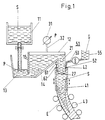
- melt S flows from a ladle 11 into a first chamber 13 of an intermediate vessel 12.
- the first chamber 13 is separated from a second chamber 14 by a partition 15.
- the second chamber 14 can be closed in a gas-tight manner and is connected to a pump 31 of a vacuum device via a connecting pipe 32.
- a negative pressure By generating a negative pressure, the melt in the chamber 14 is raised so high that a level P 13 is established in the first chamber 13 which is only slightly above the level P 41 of the melt in the mold 41.
- An immersion pouring tube 21 is fastened to the second chamber 14, the mouth 27 of which immerses in the melt S located in the mold 41.
- a lubricant G On the atmospheric ring surface of the melt S in the Mold 41 is a lubricant G from feed lines 53 provided with nozzles 52 a lubricant container 55 a lubricant supply 51 can be supplied.
- heat energy can be introduced, for example by a laser 62.
- the at least partially solidified strand E is made from the continuous casting rollers 43 oscillating mold 41 promoted.
- FIG. 2 shows a pouring device with a melt feeder identical to FIG. 1 and Strand discharge, but with a casting vessel 12 that has only one chamber is open at the top.
- An immersion pouring tube 21 is attached to the bottom of the casting vessel 12.
- the Inflow opening to the immersion pouring tube 21 is through a closing element 16, here through a plug rod 17 lockable. By adjusting the stopper rod vertically Influenced on the amount of melt leaving the casting vessel 12.
- a suction pipe 18 is connected to the immersion pouring tube 21, which is connected to a Trigger device 19 is connected. With the trigger device 19 is influence taken on the inner pressure of the immersion pouring tube 21 in such a way that the flow thread of the supplied melt always has positive pressure.
- FIG 3 shows in the upper part a section of the dip tube 21, the Mouth 27 dips into the melt S located in the mold 41. Farther the gradually forming strand shell of the solidifying strand E is shown. The arrows show the direction and size of the flow rate of the liquid metal.
- a lubricant G is applied via nozzles 52
- Feed lines 53 are arranged, fed.
- a mold powder used.
- thermo energy is applied between the dip tube 21 and the mold 41 forming the ring surface of the melt S applied, which is covered with mold powder.
- a top view of the mold 41 is shown in section AA.
- it is a slab that is formed by the broad sides 44, 46 and the long sides 45, 47 of the mold 41.
- the sides 44 to 47 enclose a cross-sectional area A K of the mold 41.
- a dip tube 21 immersed with the broad sides 22, 24 and the longitudinal sides 23, 25 with a free inner surface of A T.
- the corners 26 of the dip tube 21 are rounded, in a radius r that is greater than a quarter of the width of the immersion pouring tube B.
- Nozzles lead into the annular space formed by the dip tube 21 and the mold 41 52, which via metering devices 54 to casting agent containers 55, which are not shown in any more detail are connected.
- the metering devices 54 can be of different numbers be connected by leads 53. The options are shown with one, two, three and a larger number of feed lines 53.
Applications Claiming Priority (3)
| Application Number | Priority Date | Filing Date | Title |
|---|---|---|---|
| DE19512209 | 1995-03-21 | ||
| DE19512209A DE19512209C1 (de) | 1995-03-21 | 1995-03-21 | Verfahren und Vorrichtung zum Einfüllen metallischer Schmelze in eine Kokille |
| PCT/DE1996/000460 WO1996029164A1 (de) | 1995-03-21 | 1996-03-11 | Verfahren und vorrichtung zum einfüllen metallischer schmelze in eine kokille |
Publications (2)
| Publication Number | Publication Date |
|---|---|
| EP0814928A1 EP0814928A1 (de) | 1998-01-07 |
| EP0814928B1 true EP0814928B1 (de) | 2001-07-25 |
Family
ID=7758506
Family Applications (1)
| Application Number | Title | Priority Date | Filing Date |
|---|---|---|---|
| EP96905732A Expired - Lifetime EP0814928B1 (de) | 1995-03-21 | 1996-03-11 | Verfahren zum einfüllen metallischer schmelze in eine kokille |
Country Status (14)
| Country | Link |
|---|---|
| US (1) | US6070649A (pt) |
| EP (1) | EP0814928B1 (pt) |
| JP (1) | JP3061641B2 (pt) |
| KR (1) | KR100265206B1 (pt) |
| CN (1) | CN1084233C (pt) |
| AT (1) | ATE203438T1 (pt) |
| AU (1) | AU4938296A (pt) |
| BR (1) | BR9607672A (pt) |
| CZ (1) | CZ295697A3 (pt) |
| DE (3) | DE19512209C1 (pt) |
| RU (1) | RU2146576C1 (pt) |
| TR (1) | TR199600174A2 (pt) |
| WO (1) | WO1996029164A1 (pt) |
| ZA (1) | ZA962279B (pt) |
Families Citing this family (17)
| Publication number | Priority date | Publication date | Assignee | Title |
|---|---|---|---|---|
| FR2763524A1 (fr) * | 1997-05-23 | 1998-11-27 | Vesuvius France Sa | Installation pour la coulee continue d'un metal liquide, et organe pour cette installation |
| DE19823361A1 (de) * | 1998-05-15 | 1999-11-25 | Mannesmann Ag | Verfahren und Vorrichtung zum Abziehen eines Metallstranges |
| KR20020051088A (ko) * | 2000-12-22 | 2002-06-28 | 이구택 | 연속주조용 용융금속 공급장치 및 그 방법 |
| KR100807681B1 (ko) * | 2001-08-23 | 2008-02-28 | 주식회사 포스코 | 연속주조시 용강 공급장치 및 그 방법 |
| AT412149B (de) * | 2002-04-22 | 2004-10-25 | Arc Leichtmetallkompetenzzentrum Ranshofen Gmbh | Giesseinrichtung für leichtmetall |
| NO320254B1 (no) * | 2003-06-30 | 2005-11-14 | Norsk Hydro As | Metode og utstyr for kontinuerlig eller semikontinuerlig stoping av metall |
| US20050045303A1 (en) * | 2003-08-29 | 2005-03-03 | Jfe Steel Corporation, A Corporation Of Japan | Method for producing ultra low carbon steel slab |
| KR101203757B1 (ko) * | 2004-05-28 | 2012-11-21 | 고쿠리츠다이가쿠호진 도호쿠다이가쿠 | 금속 유리의 성형 방법 |
| NO333512B1 (no) * | 2007-12-03 | 2013-06-24 | Norsk Hydro As | Anordning ved utstyr for kontinuerlig eller semi-kontinuerlig stoping av metall |
| WO2011102748A1 (ru) * | 2010-02-19 | 2011-08-25 | Kobzar-Dernovskiy Vladimir Evgenjevich | Способ и устройство производства стали и ее непрерывной разливки |
| RU2012126008A (ru) * | 2012-06-22 | 2013-12-27 | Владимир Евгеньевич Кобзарь-Дерновский | Сталькомбайн "комкоб" кобзарь-дерновского для непрерывной ковшевой металлургии без зависомости от металлолома |
| CN102806329A (zh) * | 2012-07-17 | 2012-12-05 | 南昌大学 | 一种可进行半固态加工的有色合金连续铸胚系统 |
| NO341337B1 (en) * | 2015-07-03 | 2017-10-16 | Norsk Hydro As | Equipment for continuous or semi-continuous casting of metal with improved metal filling arrangement |
| CN105458239B (zh) * | 2016-01-07 | 2017-12-08 | 山东亨圆铜业有限公司 | 一种浇包应急装置及应急方法 |
| US10478890B1 (en) | 2016-06-21 | 2019-11-19 | Nucor Corporation | Methods of billet casting |
| CN106111934A (zh) * | 2016-08-30 | 2016-11-16 | 中国重型机械研究院股份公司 | 一种轻金属合金高速浇铸凝固成形装置及方法 |
| EP4192636B1 (de) | 2020-08-06 | 2024-02-14 | SMS Group GmbH | Anlage zum chargieren, schmelzen und giessen von metall und metalllegierungen unter vakuum und/oder schutzgasatmosphäre und verfahren zum quasi kontinuierlichen schmelzen und giessen von metall unter vakuum und/oder schutzgasatmosphäre |
Family Cites Families (9)
| Publication number | Priority date | Publication date | Assignee | Title |
|---|---|---|---|---|
| DE1140675B (de) * | 1957-10-14 | 1962-12-06 | Rheinstahl Eisenwerke Gelsenki | Zufuehrungsgefaess zum selbsttaetigen Zufuehren des Giesswerkstoffes beim Stranggiessen |
| FR1290962A (fr) * | 1961-03-08 | 1962-04-20 | Loire Atel Forges | Perfectionnements à l'alimentation des lingotières en coulée continue |
| SE356914B (pt) * | 1969-04-15 | 1973-06-12 | Voest Ag | |
| DE2105881B2 (de) * | 1971-02-01 | 1974-04-04 | Mannesmann Ag, 4000 Duesseldorf | Vorrichtung und Verfahren zum Einleiten einer Schmelze in eine Stranggießkokille |
| JPS5835051A (ja) * | 1981-08-26 | 1983-03-01 | Kawasaki Steel Corp | 連続鋳造機におけるタンデイツシユ |
| GB2234261B (en) * | 1989-07-26 | 1993-09-22 | British Steel Plc | Liquid metal processing |
| DE4006842A1 (de) * | 1990-03-05 | 1991-09-12 | Schloemann Siemag Ag | Bandgiessanlage mit oszillierender durchlaufkokille |
| DE4319966A1 (de) * | 1993-06-17 | 1994-12-22 | Didier Werke Ag | Eintauchausguß |
| US5622218A (en) * | 1995-05-15 | 1997-04-22 | Hylsa S.A. De C.V. | Method and apparatus for continuous casting of steel materials |
-
1995
- 1995-03-21 DE DE19512209A patent/DE19512209C1/de not_active Expired - Fee Related
-
1996
- 1996-03-05 TR TR96/00174A patent/TR199600174A2/xx unknown
- 1996-03-11 AU AU49382/96A patent/AU4938296A/en not_active Abandoned
- 1996-03-11 US US08/913,752 patent/US6070649A/en not_active Expired - Fee Related
- 1996-03-11 EP EP96905732A patent/EP0814928B1/de not_active Expired - Lifetime
- 1996-03-11 KR KR1019970705725A patent/KR100265206B1/ko not_active IP Right Cessation
- 1996-03-11 JP JP8527975A patent/JP3061641B2/ja not_active Expired - Lifetime
- 1996-03-11 RU RU97117342/02A patent/RU2146576C1/ru not_active IP Right Cessation
- 1996-03-11 DE DE59607366T patent/DE59607366D1/de not_active Expired - Fee Related
- 1996-03-11 DE DE19680154T patent/DE19680154D2/de not_active Expired - Fee Related
- 1996-03-11 AT AT96905732T patent/ATE203438T1/de not_active IP Right Cessation
- 1996-03-11 CN CN96192704A patent/CN1084233C/zh not_active Expired - Fee Related
- 1996-03-11 CZ CZ972956A patent/CZ295697A3/cs unknown
- 1996-03-11 BR BR9607672A patent/BR9607672A/pt not_active IP Right Cessation
- 1996-03-11 WO PCT/DE1996/000460 patent/WO1996029164A1/de not_active Application Discontinuation
- 1996-03-20 ZA ZA962279A patent/ZA962279B/xx unknown
Also Published As
| Publication number | Publication date |
|---|---|
| BR9607672A (pt) | 1998-06-16 |
| DE59607366D1 (de) | 2001-08-30 |
| TR199600174A2 (tr) | 1996-10-21 |
| DE19680154D2 (de) | 1998-05-07 |
| US6070649A (en) | 2000-06-06 |
| AU4938296A (en) | 1996-10-08 |
| DE19512209C1 (de) | 1996-07-18 |
| CN1084233C (zh) | 2002-05-08 |
| KR19980702328A (ko) | 1998-07-15 |
| RU2146576C1 (ru) | 2000-03-20 |
| ZA962279B (en) | 1996-10-07 |
| WO1996029164A1 (de) | 1996-09-26 |
| JP3061641B2 (ja) | 2000-07-10 |
| CN1179121A (zh) | 1998-04-15 |
| EP0814928A1 (de) | 1998-01-07 |
| CZ295697A3 (cs) | 1998-01-14 |
| KR100265206B1 (ko) | 2000-09-15 |
| ATE203438T1 (de) | 2001-08-15 |
| JPH10510476A (ja) | 1998-10-13 |
Similar Documents
| Publication | Publication Date | Title |
|---|---|---|
| EP0814928B1 (de) | Verfahren zum einfüllen metallischer schmelze in eine kokille | |
| DE4142447C2 (de) | Tauchgießrohr - Dünnbramme | |
| EP0035675B2 (de) | Verfahren und Einrichtung zum Horizontalstranggiessen von flüssigen Metallen, insbesondere von Stahl | |
| DE2417512C3 (de) | Eingießvorrichtung zum Einbringen von Stahl in den Gießkopf einer Stranggießkokille | |
| DE7605254U1 (de) | Einrichtung zur behandlung von metallschmelzen waehrend des stranggiessens mit spuelgas | |
| DE2747746A1 (de) | Zwischenpfannen-giesschnauze | |
| DE2105881C3 (pt) | ||
| EP0005820B1 (de) | Verfahren und Vorrichtung zum Stranggiessen von Metall in Ein- oder Mehrstranganlagen | |
| DE4116723C2 (de) | Tauchausguß | |
| EP1042087B1 (de) | Einrichtung zur zuführung von metallschmelze | |
| DE2548585A1 (de) | Vorrichtung zum stranggiessen von stahl | |
| DE2012691B2 (de) | Anwendung eines verfahrens zum vergiessen von eisenmetallen auf das vergiessen aluminiumberuhigter staehle | |
| EP0996513B1 (de) | Verfahren und vorrichtung zum erzeugen von brammen | |
| DE3917403C2 (de) | Verfahren und Vorrichtung zum Füllen einer Stranggießkokille mit metallischer Schmelze | |
| DE2607379B2 (de) | Vorrichtung zum spuelen von stahl | |
| DE10195658B4 (de) | Vorrichtung und Verfahren zum Zuführen von geschmolzenem Metall in eine Form beim Stranggießen | |
| DE4332760A1 (de) | Verfahren zum Betreiben einer Niederdruckmetallgießvorrichtung und Niederdruckmetallgießvorrichtung dafür | |
| DE3136847C1 (de) | Verfahren und Vorrichtung zum Horizontalstranggiessen von fluessigen Metallen,insbesondere von Stahl | |
| DE8233113U1 (de) | Schwimmer fuer metallschmelzen | |
| EP0902736B1 (de) | Verfahren und vorrichtung zum ausgiessen von stahl aus einem tauchausguss | |
| DE3490299C2 (pt) | ||
| CH624863A5 (en) | Method for preventing the accumulation of oxidic inclusions during the casting of deoxidised steels | |
| DE2830523C2 (de) | Verfahren zum Gießen eines Metallblocks in einer Kokille und Vorrichtung zum Durchführen des Verfahrens | |
| DE3301881C2 (de) | Verfahren und Vorrichtung zum Horizontalstranggießen, insbesondere von Stahl | |
| DE2839870A1 (de) | Verfahren und vorrichtung zum metallguss |
Legal Events
| Date | Code | Title | Description |
|---|---|---|---|
| PUAI | Public reference made under article 153(3) epc to a published international application that has entered the european phase |
Free format text: ORIGINAL CODE: 0009012 |
|
| 17P | Request for examination filed |
Effective date: 19970908 |
|
| AK | Designated contracting states |
Kind code of ref document: A1 Designated state(s): AT BE DE FR GB IT NL |
|
| 17Q | First examination report despatched |
Effective date: 19980618 |
|
| RAP1 | Party data changed (applicant data changed or rights of an application transferred) |
Owner name: SMS DEMAG AG |
|
| RTI1 | Title (correction) |
Free format text: METHOD FOR POURING A METAL MELT INTO A MOULD |
|
| GRAG | Despatch of communication of intention to grant |
Free format text: ORIGINAL CODE: EPIDOS AGRA |
|
| GRAG | Despatch of communication of intention to grant |
Free format text: ORIGINAL CODE: EPIDOS AGRA |
|
| GRAH | Despatch of communication of intention to grant a patent |
Free format text: ORIGINAL CODE: EPIDOS IGRA |
|
| GRAH | Despatch of communication of intention to grant a patent |
Free format text: ORIGINAL CODE: EPIDOS IGRA |
|
| GRAA | (expected) grant |
Free format text: ORIGINAL CODE: 0009210 |
|
| AK | Designated contracting states |
Kind code of ref document: B1 Designated state(s): AT BE DE FR GB IT NL |
|
| REF | Corresponds to: |
Ref document number: 203438 Country of ref document: AT Date of ref document: 20010815 Kind code of ref document: T |
|
| GBT | Gb: translation of ep patent filed (gb section 77(6)(a)/1977) |
Effective date: 20010726 |
|
| REF | Corresponds to: |
Ref document number: 59607366 Country of ref document: DE Date of ref document: 20010830 |
|
| ET | Fr: translation filed | ||
| REG | Reference to a national code |
Ref country code: GB Ref legal event code: IF02 |
|
| PGFP | Annual fee paid to national office [announced via postgrant information from national office to epo] |
Ref country code: GB Payment date: 20020222 Year of fee payment: 7 |
|
| PGFP | Annual fee paid to national office [announced via postgrant information from national office to epo] |
Ref country code: NL Payment date: 20020228 Year of fee payment: 7 |
|
| PGFP | Annual fee paid to national office [announced via postgrant information from national office to epo] |
Ref country code: AT Payment date: 20020307 Year of fee payment: 7 |
|
| PGFP | Annual fee paid to national office [announced via postgrant information from national office to epo] |
Ref country code: DE Payment date: 20020309 Year of fee payment: 7 |
|
| PGFP | Annual fee paid to national office [announced via postgrant information from national office to epo] |
Ref country code: FR Payment date: 20020315 Year of fee payment: 7 |
|
| PGFP | Annual fee paid to national office [announced via postgrant information from national office to epo] |
Ref country code: BE Payment date: 20020322 Year of fee payment: 7 |
|
| PLBE | No opposition filed within time limit |
Free format text: ORIGINAL CODE: 0009261 |
|
| STAA | Information on the status of an ep patent application or granted ep patent |
Free format text: STATUS: NO OPPOSITION FILED WITHIN TIME LIMIT |
|
| 26N | No opposition filed | ||
| PG25 | Lapsed in a contracting state [announced via postgrant information from national office to epo] |
Ref country code: GB Free format text: LAPSE BECAUSE OF NON-PAYMENT OF DUE FEES Effective date: 20030311 Ref country code: AT Free format text: LAPSE BECAUSE OF NON-PAYMENT OF DUE FEES Effective date: 20030311 |
|
| PG25 | Lapsed in a contracting state [announced via postgrant information from national office to epo] |
Ref country code: BE Free format text: LAPSE BECAUSE OF NON-PAYMENT OF DUE FEES Effective date: 20030331 |
|
| BERE | Be: lapsed |
Owner name: *SMS DEMAG A.G. Effective date: 20030331 |
|
| PG25 | Lapsed in a contracting state [announced via postgrant information from national office to epo] |
Ref country code: NL Free format text: LAPSE BECAUSE OF NON-PAYMENT OF DUE FEES Effective date: 20031001 Ref country code: DE Free format text: LAPSE BECAUSE OF NON-PAYMENT OF DUE FEES Effective date: 20031001 |
|
| GBPC | Gb: european patent ceased through non-payment of renewal fee |
Effective date: 20030311 |
|
| PG25 | Lapsed in a contracting state [announced via postgrant information from national office to epo] |
Ref country code: FR Free format text: LAPSE BECAUSE OF NON-PAYMENT OF DUE FEES Effective date: 20031127 |
|
| NLV4 | Nl: lapsed or anulled due to non-payment of the annual fee |
Effective date: 20031001 |
|
| REG | Reference to a national code |
Ref country code: FR Ref legal event code: ST |
|
| PG25 | Lapsed in a contracting state [announced via postgrant information from national office to epo] |
Ref country code: IT Free format text: LAPSE BECAUSE OF NON-PAYMENT OF DUE FEES;WARNING: LAPSES OF ITALIAN PATENTS WITH EFFECTIVE DATE BEFORE 2007 MAY HAVE OCCURRED AT ANY TIME BEFORE 2007. THE CORRECT EFFECTIVE DATE MAY BE DIFFERENT FROM THE ONE RECORDED. Effective date: 20050311 |