EP0814928B1 - Method for pouring a metal melt into a mould - Google Patents
Method for pouring a metal melt into a mould Download PDFInfo
- Publication number
- EP0814928B1 EP0814928B1 EP96905732A EP96905732A EP0814928B1 EP 0814928 B1 EP0814928 B1 EP 0814928B1 EP 96905732 A EP96905732 A EP 96905732A EP 96905732 A EP96905732 A EP 96905732A EP 0814928 B1 EP0814928 B1 EP 0814928B1
- Authority
- EP
- European Patent Office
- Prior art keywords
- melt
- mould
- supplied
- chamber
- casting
- Prior art date
- Legal status (The legal status is an assumption and is not a legal conclusion. Google has not performed a legal analysis and makes no representation as to the accuracy of the status listed.)
- Expired - Lifetime
Links
- 238000000034 method Methods 0.000 title claims abstract description 16
- 239000002184 metal Substances 0.000 title abstract description 11
- 238000005266 casting Methods 0.000 claims abstract description 18
- 229910000831 Steel Inorganic materials 0.000 claims abstract description 5
- 239000010959 steel Substances 0.000 claims abstract description 5
- 239000000155 melt Substances 0.000 claims description 23
- 239000000314 lubricant Substances 0.000 claims description 16
- 239000007788 liquid Substances 0.000 claims description 5
- 230000001105 regulatory effect Effects 0.000 claims description 3
- 238000007654 immersion Methods 0.000 abstract description 17
- 238000009749 continuous casting Methods 0.000 description 4
- 238000010438 heat treatment Methods 0.000 description 4
- IHQKEDIOMGYHEB-UHFFFAOYSA-M sodium dimethylarsinate Chemical class [Na+].C[As](C)([O-])=O IHQKEDIOMGYHEB-UHFFFAOYSA-M 0.000 description 4
- 239000003795 chemical substances by application Substances 0.000 description 3
- 229910001338 liquidmetal Inorganic materials 0.000 description 2
- 238000005192 partition Methods 0.000 description 2
- 239000000843 powder Substances 0.000 description 2
- 230000009286 beneficial effect Effects 0.000 description 1
- 230000009189 diving Effects 0.000 description 1
- 230000003189 isokinetic effect Effects 0.000 description 1
- 238000004519 manufacturing process Methods 0.000 description 1
- 239000012768 molten material Substances 0.000 description 1
- 238000000926 separation method Methods 0.000 description 1
- 230000008646 thermal stress Effects 0.000 description 1
Images


Classifications
-
- B—PERFORMING OPERATIONS; TRANSPORTING
- B22—CASTING; POWDER METALLURGY
- B22D—CASTING OF METALS; CASTING OF OTHER SUBSTANCES BY THE SAME PROCESSES OR DEVICES
- B22D11/00—Continuous casting of metals, i.e. casting in indefinite lengths
- B22D11/10—Supplying or treating molten metal
-
- B—PERFORMING OPERATIONS; TRANSPORTING
- B22—CASTING; POWDER METALLURGY
- B22D—CASTING OF METALS; CASTING OF OTHER SUBSTANCES BY THE SAME PROCESSES OR DEVICES
- B22D41/00—Casting melt-holding vessels, e.g. ladles, tundishes, cups or the like
- B22D41/50—Pouring-nozzles
-
- B—PERFORMING OPERATIONS; TRANSPORTING
- B22—CASTING; POWDER METALLURGY
- B22D—CASTING OF METALS; CASTING OF OTHER SUBSTANCES BY THE SAME PROCESSES OR DEVICES
- B22D11/00—Continuous casting of metals, i.e. casting in indefinite lengths
- B22D11/07—Lubricating the moulds
-
- B—PERFORMING OPERATIONS; TRANSPORTING
- B22—CASTING; POWDER METALLURGY
- B22D—CASTING OF METALS; CASTING OF OTHER SUBSTANCES BY THE SAME PROCESSES OR DEVICES
- B22D11/00—Continuous casting of metals, i.e. casting in indefinite lengths
- B22D11/10—Supplying or treating molten metal
- B22D11/11—Treating the molten metal
- B22D11/113—Treating the molten metal by vacuum treating
Abstract
Description
Die Erfindung betrifft ein Verfahren zum Einfüllen metallischer Schmelze, insbesondere Stahl, über ein an einem Gieß behälter befestigten Tauchausguß zur einer vertikal oszillierenden Kokille befindlichen Schmelze. Aus der JP 58 035 051 ist ein derartiges Verfahren bekannt, wobei die hierbei beschriebene Vorrichtung ein Zwischengefäß mit einer offenen ersten Kammer aufweist, in die Metallschmelze aus einer Gießpfanne zugeführt wird, und eine geschlossene mit einer Unterdruckeinrichtung verbundene zweite Kammer besitzt, in dessen Boden ein Tauchrohr vorgesehen ist, das in vertikal oszillierbare Kokille hineinragt.The invention relates to a method for filling metallic melt, in particular Steel, vertically through a submerged nozzle attached to a casting tank oscillating mold located melt. Such a method is known from JP 58 035 051, the device described here being a Intermediate vessel with an open first chamber has, into which molten metal is fed from a ladle, and a has a closed second chamber connected to a vacuum device, in the bottom of which is provided an immersion tube which is in a vertically oscillatable mold protrudes.
Aus EP 0 410 273 ist ein Behälter mit einer ersten, gegen Atmosphärendruck offenen Kammer zur Aufnahme schmelzflüssigen Materials und einer damit über eine mit Öffnung versehene Wand verbundenen zweiten Kammer zur Abgabe von Metall bekannt, wobei die zweite Kammer abgedichtet und an eine Unterdruckeinrichtung angeschlossen ist, um dadurch in der zweiten Kammer ein höheres Metallniveau als in der ersten Kammer einzustellen. In der zweiten Kammer ist ein nicht näher beschriebener Auslaß vorgesehen, der durch ein Ventil verschließbar ist.EP 0 410 273 discloses a container with a first one that is open to atmospheric pressure Chamber for holding molten material and one with it Opening provided wall connected second chamber for dispensing metal known, the second chamber sealed and connected to a vacuum device is connected to thereby have a higher metal level in the second chamber than in the first chamber. In the second chamber, one is not closer described outlet provided, which can be closed by a valve.
Aus DE-OS 2017469 ist eine Anlage zum Stranggießen von schmelzflüssigem Metall mit einer Stranggießkokille bekannt, die ein gasdicht abschließbares und evakuierbares Zwischengefäß aufweist, bei der ein Unterdruck einstellbar ist, der das Metall aus dem Auslaufrohr praktisch drucklos in die Kokille einfließen läßt. DE-OS 2017469 describes a system for the continuous casting of molten metal known with a continuous casting mold, which is a gas-tight lockable and Evacuable intermediate vessel, in which a negative pressure is adjustable, which Allows metal to flow into the mold from the outlet pipe practically without pressure.
Das hieraus bekannte Tauchgießrohr ist so ausgestaltet, daß immer noch der Metallstrahl in den flüssigen Sumpf eindringt, auch wenn die Geschwindigkeit des ausfließenden Metalls durch eine trichterförmige Ausgestaltung im Mündungsbereich des Auslaufrohres weiter vermindert wird.The immersion pouring tube known from this is designed so that the Metal jet penetrates the liquid sump, even if the speed of the flowing metal through a funnel-shaped design in the mouth area of the outlet pipe is further reduced.
Die Erfindung hat sich das Ziel gesetzt, ein Verfahren zu schaffen, das ein an kinetischer Energie freies, strömungsberuhigtes Eingießen der Metallschmelze in die Kokille ermöglicht, insbesondere zur Erzeugung von Dünn brammen.The invention has set itself the goal of a method create a flow-free pouring of the Metal melt in the mold allows, in particular for the production of Slab thinly.
Die Erfindung erreicht dieses Ziel durch die Merkmale des Verfahrensanspruches 1. Vorzugsweise Ausgestaltungen ergeben sich aus den Unteransprüchen.The invention achieves this goal by the features of Process claim 1. Refinements preferably result from the subclaims.
Erfindungsgemäß wird die hydraulische Höhe der zugeführten Schmelze eingestellt und die das Zwischengefäß verlassende Schmelze wird isokinetisch dem flüssigen Teil des Stahlstranges zugeführt. Das Einstellen der hydraulischen Höhe zwischen 50 bis 600 mm oberhalb des in der Kokille befindlichen Pegels der Schmelze wird einmal erreicht, das auf ein zwei Kammern aufweisendes Zwischengefäß auf die Oberfläche der in der zweiten Kammer befindlichen Schmelze ein Unterdruck ausgeübt wird und zwar in einer Größenordnung, daß der Pegel des der Atmosphäre ausgesetzten Oberfläche der Schmelze im Zwischengefäß geringfügig über den in der Kokille befindlichen Pegel sich einstellt.According to the invention, the hydraulic level of the melt supplied is set and the melt leaving the intermediate vessel becomes isokinetic fed liquid part of the steel strand. Adjusting the hydraulic height between 50 to 600 mm above the melt level in the mold is reached once, the on a two-chamber intermediate vessel on the Surface of the melt in the second chamber is a negative pressure is exercised on the order of magnitude that the level of the atmosphere exposed surface of the melt in the tundish slightly above that in the The mold level is set.
Die hydraulische Höhe wird in einer zweiten Ausführungsform in der Weise eingestellt, daß die Zuflußmenge über ein Verschlußorgan geregelt wird und der Stromfaden im Tauchgießrohr stets einen positiven Druck aufweist.In a second embodiment, the hydraulic height is set in such a way that the inflow amount is regulated by a closure member and the flow thread in Immersion tube always has a positive pressure.
Die zufließende Menge des flüssigen Metalls wird jeweils so eingestellt, daß sie der abgezogenen Menge des teilerstarrten Stranges entspricht. Durch dieses Verfahren wird der sonst übliche Gießstrahl, der in den flüssigen Strangkern eindringt, vermieden. Dies bringt insbesondere den Vorteil mit sich, daß eine völlig ebene Badoberfläche entsteht, die ein exaktes gleichmäßiges Einbringen des Gießmittels erlaubt. Weiterhin wird die Strangschale gleichmäßig und ungehindert erstarren, was nicht nur die Oberfläche verbessert, sondern auch die Durchbruchneigung vermindert. Weiterhin wird ein Gießen von Strängen mit großem Längen-/Breitenverhältnis möglich, da keinerlei unerwünschte Querströmung innerhalb der Kokille stattfindet. The inflowing amount of the liquid metal is adjusted so that it is the deducted amount of the partially solidified strand corresponds. Through this procedure the usual pouring stream that penetrates into the liquid strand core, avoided. This has the particular advantage that a completely flat Bath surface arises, which ensures an exact, even introduction of the casting agent allowed. Furthermore, the strand shell will solidify evenly and unhindered, what not only improves the surface, but also reduces the tendency to break through. Furthermore, casting strands with a large length / width ratio possible because there is no unwanted cross flow inside the mold.
Die Querschnittsflächen vom Tauchgießrohr und Kokille sind so gewählt, daß unabhängig vom Pegel die frei der Atmosphäre ausgesetzte Ringfläche eine konstante Breite aufweist. In vorteilhafter Weise können Maßnahmen zur Einflußnahme auf das Gleitmittel durchgeführt werden. Hierzu zählt insbesondere ein einfaches Aufheizen des Gleitmittels und eine gezielte Dosierung.The cross-sectional areas of the dip tube and mold are chosen so that regardless of the level, the ring surface exposed to the atmosphere is constant Width. Measures for influencing the Lubricants are carried out. In particular, this includes simple heating of the lubricant and a targeted dosage.
Die Mündung des Tauchgießrohres sollte eine Querschnittsfläche auf weisen die nicht kleiner als das 0,3-fache bis 0,9-fache des Innenquerschnitts der Durchtrittsfläche der Kokille beträgt. Zur Minderung der thermischen Spannungen des Mantels des Tauchgießrohres ist es vorteilhalt, die Ecken des Tauchgießrohres abzurunden und zwar in einem Radius, der größer als ein Viertel der Tauchgießrohrbreite ist.The mouth of the immersion pouring tube should have a cross-sectional area have not less than 0.3 times to 0.9 times the inner cross section of the passage area of the Mold is. To reduce the thermal stresses of the jacket of the Dip tube, it is beneficial to round the corners of the dip tube in a radius that is larger than a quarter of the immersion tube width.
Zur Steigerung der sicheren Zufuhr des Gleitmittels ist es zweckmäßig, Eintauchdüsen entlang der Kokilleninnenwandung sich an dieser anlehnend anzuordnen. Das Gleitmittel kann dabei unter Druck in der erforderlichen Menge in das Bad an der gewünschten Trennstelle zwischen Kokille und Schmelze eingebracht werden.To increase the safe supply of lubricant, it is advisable to Immersion nozzles along the inner wall of the mold leaning against it to arrange. The lubricant can under pressure in the required amount in the Bath is introduced at the desired separation point between the mold and the melt become.
Neben der vom Schmelzbad abgegebenen Wärme kann das Gleitmittel noch durch Fremdenergie erhitzt werden. So wird vorgeschlagen, einen Laser einzusetzen, dessen Laserstrahl auf der Oberfläche steuerbar geführt wird und so exakt die erforderliche Wärmeenergie abgibt.In addition to the heat given off by the weld pool, the lubricant can External energy to be heated. So it is suggested to use a laser whose laser beam is guided on the surface in a controllable manner and thus exactly emits the required thermal energy.
Das erfindungsgemäße Gießverfahren ist für beliebe Formate einsetzbar wie rund, Knüppel oder Bramme. Es eignet sich in besonderer Weise auch für Dünnbrammen mit Abmessungen beispielsweise 60 mm x 1.500 mm.The casting method according to the invention can be used for any formats such as round, Billets or slabs. It is also particularly suitable for thin slabs with dimensions, for example, 60 mm x 1,500 mm.
Ein Beispiel der Erfindung ist in der beiliegenden Zeichnung dargelegt. So zeigen:
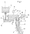
- Figur 1
- Schnitt durch die Gießeinrichtung mit Zweikammerngefäß
- Figur 2
- Schnitt durch die Gießeinrichtung mit offenem Gefäß
- Figur 3
- Schnitt und Draufsicht durch das Tauchgießrohr und die Kokille.
- Figure 1
- Section through the pouring device with two-chamber vessel
- Figure 2
- Cut through the pouring device with the vessel open
- Figure 3
- Section and top view through the dip tube and the mold.
In der Figur 1 fließt Schmelze S aus einer Gießpfanne 11 in eine erste Kammer 13
eines Zwischengefäßes 12. Die erste Kammer 13 ist durch eine Trennwand 15 von
einer zweiten Kammer 14 getrennt. Die zweite Kammer 14 ist gasdicht verschließbar
und über ein Verbindungsrohr 32 mit einer Pumpe 31 einer Unterdruckeinrichtung
verbunden. Durch Erzeugen eines Unterdrucks wird die Schmelze in der Kammer 14
so hoch angehoben, daß sich in der ersten Kammer 13 ein solcher Pegel P13 einstellt,
der nur geringfügig über dem Pegel P41 der in der Kokille 41 befindlichen Schmelze
liegt.
An der zweiten Kammer 14 ist ein Tauchgießrohr 21 befestigt, dessen Mündung 27 in
die in der Kokille 41 befindlichen Schmelze S eintaucht.In FIG. 1, melt S flows from a
An
Auf die mit der Atmosphäre in Verbindung stehende Ringfläche der Schmelze S in der
Kokille 41 ist ein Gleitmittel G über mit Düsen 52 versehenen Zuleitungen 53 aus
einem Gleitmittelbehälter 55 einer Gleitmittelzuführung 51 zuführbar.On the atmospheric ring surface of the melt S in the
Mold 41 is a lubricant G from
Weiterhin ist auf die Oberfläche der Ringfläche der Schmelze S in der Kokille 41 über
eine Heizeinrichtung 61 Wärmeenergie einbringbar, beispielsweise durch einen Laser
62.Furthermore, the surface of the annular surface of the melt S in the
Der zumindest teilerstarrte Strang E wird über Stranggießrollen 43 aus der
oszillierenden Kokille 41 gefördert.The at least partially solidified strand E is made from the
Die Figur 2 zeigt eine Gießeinrichtung mit zur Figur 1 identischer Schmelzenzufuhr und
Strangabfuhr, aber mit einem Gießgefäß 12, das nur eine Kammer aufweist, nach
oben offen ist. Am Boden des Gießgefäßes 12 ist ein Tauchgießrohr 21 befestigt. Die
Zuflußöffnung zum Tauchgießrohr 21 ist durch ein Verschließelement 16, hier durch
eine Stopfenstange 17 absperrbar. Durch vertikales Verstellen der Stopfenstange wird
Einfluß auf die das Gießgefäß 12 verlassende Schmelzenmenge genommen.FIG. 2 shows a pouring device with a melt feeder identical to FIG. 1 and
Strand discharge, but with a
An das Tauchgießrohr 21 ist ein Absaugrohr 18 angeschlossen, das mit einer
Abzugsvorrichtung 19 in Verbindung steht. Mit der Abzugsvorrichtung 19 wird Einfluß
auf den Inneridruck des Tauchgießrohres 21 genommen und zwar in der Weise, daß
der Stromfaden der zugeführten Schmelze stets positiven Druck aufweist. A
Die Figur 3 zeigt im oberen Teil einen Ausschnitt des Tauchrohres 21, dessen
Mündung 27 in die sich in der Kokille 41 befindende Schmelze S eintaucht. Weiterhin
ist die sich allmählich bildende Strangschale des erstarrenden Stranges E dargestellt.
Die Pfeile zeigen Richtung und Größe der Fließgeschwindigkeit des flüssigen Metalls.3 shows in the upper part a section of the
Oberhalb der Oberkante 42 der Kokille 41 wird ein Gleitmittel G über Düsen 52, die an
Zuleitungen 53 angeordnet sind, zugeleitet. Üblicherweise wird ein Gießpulver
eingesetzt.Above the
Durch eine Heizeinrichtung 61, hier als Lasergerät 62 wird Wärmeenergie auf die sich
zwischen dem Tauchrohr 21 und der Kokille 41 bildende Ringoberfläche der Schmelze
S aufgebracht, die mit Gießpulver bedeckt ist.By means of a
Im unteren Teil der Figur 3 ist eine Draufsicht auf die Kokille 41 im Schnitt AA
dargestellt. Im vorliegenden Fall handelt es sich um eine Bramme, die durch die
Breitseiten 44, 46 und die Längsseiten 45, 47 der Kokille 41 geformt wird. Die Seiten
44 bis 47 umschließen dabei eine Querschnittsfläche AK der Kokille 41.In the lower part of FIG. 3, a top view of the
In diesen Innenraum taucht ein Tauchrohr 21 ein mit den Breitseiten 22, 24 und den
Längsseiten 23, 25 mit einer freien Innenfläche von AT.In this interior space, a
Die Ecken 26 des Tauchrohres 21 sind abgerundet, und zwar in einem Radius r, der
größer als ein Viertel der Breite des Tauchgießrohres B ist.The corners 26 of the
In den von dem Tauchrohr 21 und der Kokille 41 gebildeten Ringraum führen Düsen
52, die über Dosiereinrichtungen 54 an nicht weiter dargestellte Gießmittelbehälter 55
angeschlossen sind. Die Dosiereinrichtungen 54 können mit unterschiedlicher Anzahl
von Zuleitungen 53 verbunden sein. Dargestellt sind die Möglichkeiten mit einer, zwei,
drei und einer größeren Zahl von Zuleitungen 53. Nozzles lead into the annular space formed by the
- 1111
- GießpfanneLadle
- 1212th
- GießbehälterCasting tank
- 1313
- Erste KammerFirst chamber
- 1414
- Zweite KammerSecond chamber
- 1515
- Trennwandpartition wall
- 1616
- VerschließelementClosing element
- 1717th
- StopfenstangePlug rod
- 1818th
- AbsaugrohrExhaust pipe
- 1919th
- AbzugsvorrichtungTrigger device
- 2121
- TauchgießrohrImmersion pouring tube
- 22, 2422, 24
- BreitseitenBroadsides
- 23, 2523, 25
- LängsseitenLong sides
- 2626
- EckenCorners
- 2727
- Mündungmuzzle
- 3131
- Pumpepump
- 3232
- VerbindungsrohrConnecting pipe
- 4141
- KokilleMold
- 4242
- OberkanteTop edge
- 4343
- StranggießrollenContinuous casting rolls
- 44, 4644, 46
- 3 Breitseiten3 broadsides
- 45, 4745, 47
- LängsseitenLong sides
- 5151
- GleitmittelzuführungLubricant supply
- 5252
- DüsenNozzles
- 5353
- Zuleitungen Supply lines
- 5454
- DosiereinrichtungDosing device
- 5555
- GleitmittelbehälterLubricant reservoir
- 6161
- HeizeinrichtungHeating device
- 6262
- Laserlaser
- ATAT
- Querschnittsfläche TauchgießrohrCross-sectional area immersion pouring tube
- AKAK
- Querschnittsfläche KokilleCross-sectional area of mold
- rr
- Radius Ecken 26Radius corners 26
- BB
- Breite TauchgießrohrWide immersion pipe
- GG
- GießmittelCasting agent
- PP
- Pegellevel
- ss
- Schmelzemelt
- EE
- Erstarrter StrangSolidified strand
Claims (8)
- Method for supplying metallic melt, in particular steel, via a submerged casting nozzle, which is attached to a casting vessel, to the melt located in a vertically oscillating mould,
characterised in
that the melt leaving the casting vessel through the submerged casting nozzle is isokinetically supplied to the liquid part of the strand which is conveyed out of the mould, for which purpose the hydraulic head of the supplied melt is adjusted such that it lies between 50 and 600 mm higher than the melt located in the mould, and
the melt is supplied to the mould interior with a cross-sectional area (AT) which is only slightly smaller than the cross-sectional area (AK) of the melt located in the mould interior. - Method for supplying metallic melt according to Claim 1,
characterised in
that, in order to adjust the hydraulic head, a part of the melt which is located in a casting vessel having two chambers and which is in contact with the mould is subjected to an underpressure which is such that the level of the surface of the melt which is exposed to the atmosphere in the casting vessel lies above the level in the mould. - Method for supplying metallic melt according to Claim 1,
characterised in
that, in order to adjust the hydraulic head, the stream filament of the supplied melt is always at positive pressure from the time when casting commences, and that the quantity flowing in is supplied in regulated fashion. - Method for supplying metallic melt according to Claim 1,
characterised in
that the annular area, which is exposed to the free atmosphere, of the melt in the mould surrounds the submerged nozzle with a constant width, irrespective of the level. - Method for supplying metallic melt according to Claim 4,
characterised in that a lubricant is uniformly supplied to the ring of the melt which surrounds the submerged nozzle. - Method for supplying metallic melt according to Claim 5,
characterised in
that the lubricant is supplied in liquid form. - Method for supplying metallic melt according to Claim 5 or 6,
characterised in
that the lubricant is heated by external energy. - Method for supplying metallic melt according to any one of the preceding Claims,
characterised in
that the lubricant is pressurised and supplied such that it can be regulated in terms of quantity.
Applications Claiming Priority (3)
| Application Number | Priority Date | Filing Date | Title |
|---|---|---|---|
| DE19512209 | 1995-03-21 | ||
| DE19512209A DE19512209C1 (en) | 1995-03-21 | 1995-03-21 | Appts. for delivering metal melt into continuous casting mould |
| PCT/DE1996/000460 WO1996029164A1 (en) | 1995-03-21 | 1996-03-11 | Method and device for pouring a metal melt into a mould |
Publications (2)
| Publication Number | Publication Date |
|---|---|
| EP0814928A1 EP0814928A1 (en) | 1998-01-07 |
| EP0814928B1 true EP0814928B1 (en) | 2001-07-25 |
Family
ID=7758506
Family Applications (1)
| Application Number | Title | Priority Date | Filing Date |
|---|---|---|---|
| EP96905732A Expired - Lifetime EP0814928B1 (en) | 1995-03-21 | 1996-03-11 | Method for pouring a metal melt into a mould |
Country Status (14)
| Country | Link |
|---|---|
| US (1) | US6070649A (en) |
| EP (1) | EP0814928B1 (en) |
| JP (1) | JP3061641B2 (en) |
| KR (1) | KR100265206B1 (en) |
| CN (1) | CN1084233C (en) |
| AT (1) | ATE203438T1 (en) |
| AU (1) | AU4938296A (en) |
| BR (1) | BR9607672A (en) |
| CZ (1) | CZ295697A3 (en) |
| DE (3) | DE19512209C1 (en) |
| RU (1) | RU2146576C1 (en) |
| TR (1) | TR199600174A2 (en) |
| WO (1) | WO1996029164A1 (en) |
| ZA (1) | ZA962279B (en) |
Families Citing this family (17)
| Publication number | Priority date | Publication date | Assignee | Title |
|---|---|---|---|---|
| FR2763524A1 (en) * | 1997-05-23 | 1998-11-27 | Vesuvius France Sa | Molten metal continuous casting installation for production of thin slabs or strip |
| DE19823361A1 (en) * | 1998-05-15 | 1999-11-25 | Mannesmann Ag | Continuous billet extraction |
| KR20020051088A (en) * | 2000-12-22 | 2002-06-28 | 이구택 | Molten metal supply method and equipment for continuous casting |
| KR100807681B1 (en) * | 2001-08-23 | 2008-02-28 | 주식회사 포스코 | Molten steel feeding apparatus and thereof method for the continuous casting |
| AT412149B (en) * | 2002-04-22 | 2004-10-25 | Arc Leichtmetallkompetenzzentrum Ranshofen Gmbh | CASTING DEVICE FOR LIGHT METAL |
| NO320254B1 (en) * | 2003-06-30 | 2005-11-14 | Norsk Hydro As | Method and equipment for continuous or semi-continuous stopping of metal |
| US20050045303A1 (en) * | 2003-08-29 | 2005-03-03 | Jfe Steel Corporation, A Corporation Of Japan | Method for producing ultra low carbon steel slab |
| KR101203757B1 (en) * | 2004-05-28 | 2012-11-21 | 고쿠리츠다이가쿠호진 도호쿠다이가쿠 | Method for forming metallic glass |
| NO333512B1 (en) * | 2007-12-03 | 2013-06-24 | Norsk Hydro As | Device for equipment for continuous or semi-continuous stopping of metal |
| WO2011102748A1 (en) * | 2010-02-19 | 2011-08-25 | Kobzar-Dernovskiy Vladimir Evgenjevich | Method and apparatus for producing steel, and the continuous casting of steel |
| RU2012126008A (en) * | 2012-06-22 | 2013-12-27 | Владимир Евгеньевич Кобзарь-Дерновский | STEEL COMBINE "KOMBOB" KOBZAR-DERNOVSKY FOR CONTINUOUS DUCK METALLURGY WITHOUT DEPENDENCE ON THE METALLOMA |
| CN102806329A (en) * | 2012-07-17 | 2012-12-05 | 南昌大学 | Continuous blank casting system capable of performing semi-solid processing on non-ferrous alloy |
| NO341337B1 (en) * | 2015-07-03 | 2017-10-16 | Norsk Hydro As | Equipment for continuous or semi-continuous casting of metal with improved metal filling arrangement |
| CN105458239B (en) * | 2016-01-07 | 2017-12-08 | 山东亨圆铜业有限公司 | A kind of casting ladle emergency set and emergency method |
| US10478890B1 (en) | 2016-06-21 | 2019-11-19 | Nucor Corporation | Methods of billet casting |
| CN106111934A (en) * | 2016-08-30 | 2016-11-16 | 中国重型机械研究院股份公司 | A kind of light metal alloy high speed casting solidification forming device and method |
| EP4192636B1 (en) | 2020-08-06 | 2024-02-14 | SMS Group GmbH | System for charging, melting and casting metal and metal alloys in a vacuum and/or shielding gas atmosphere and method for quasi-continuous melting and casting of metal in a vacuum and/or shielding gas atmosphere |
Family Cites Families (9)
| Publication number | Priority date | Publication date | Assignee | Title |
|---|---|---|---|---|
| DE1140675B (en) * | 1957-10-14 | 1962-12-06 | Rheinstahl Eisenwerke Gelsenki | Feeding vessel for the automatic feeding of the casting material during continuous casting |
| FR1290962A (en) * | 1961-03-08 | 1962-04-20 | Loire Atel Forges | Improvements in the feeding of continuous casting molds |
| SE356914B (en) * | 1969-04-15 | 1973-06-12 | Voest Ag | |
| DE2105881B2 (en) * | 1971-02-01 | 1974-04-04 | Mannesmann Ag, 4000 Duesseldorf | Device and method for introducing a melt into a continuous casting mold |
| JPS5835051A (en) * | 1981-08-26 | 1983-03-01 | Kawasaki Steel Corp | Tundish in continuous casting machine |
| GB2234261B (en) * | 1989-07-26 | 1993-09-22 | British Steel Plc | Liquid metal processing |
| DE4006842A1 (en) * | 1990-03-05 | 1991-09-12 | Schloemann Siemag Ag | Strip casting assembly - has die head with flow guides to prevent turbulence in molten metal passing to the mouthpiece |
| DE4319966A1 (en) * | 1993-06-17 | 1994-12-22 | Didier Werke Ag | Immersion spout |
| US5622218A (en) * | 1995-05-15 | 1997-04-22 | Hylsa S.A. De C.V. | Method and apparatus for continuous casting of steel materials |
-
1995
- 1995-03-21 DE DE19512209A patent/DE19512209C1/en not_active Expired - Fee Related
-
1996
- 1996-03-05 TR TR96/00174A patent/TR199600174A2/en unknown
- 1996-03-11 AU AU49382/96A patent/AU4938296A/en not_active Abandoned
- 1996-03-11 US US08/913,752 patent/US6070649A/en not_active Expired - Fee Related
- 1996-03-11 EP EP96905732A patent/EP0814928B1/en not_active Expired - Lifetime
- 1996-03-11 KR KR1019970705725A patent/KR100265206B1/en not_active IP Right Cessation
- 1996-03-11 JP JP8527975A patent/JP3061641B2/en not_active Expired - Lifetime
- 1996-03-11 RU RU97117342/02A patent/RU2146576C1/en not_active IP Right Cessation
- 1996-03-11 DE DE59607366T patent/DE59607366D1/en not_active Expired - Fee Related
- 1996-03-11 DE DE19680154T patent/DE19680154D2/en not_active Expired - Fee Related
- 1996-03-11 AT AT96905732T patent/ATE203438T1/en not_active IP Right Cessation
- 1996-03-11 CN CN96192704A patent/CN1084233C/en not_active Expired - Fee Related
- 1996-03-11 CZ CZ972956A patent/CZ295697A3/en unknown
- 1996-03-11 BR BR9607672A patent/BR9607672A/en not_active IP Right Cessation
- 1996-03-11 WO PCT/DE1996/000460 patent/WO1996029164A1/en not_active Application Discontinuation
- 1996-03-20 ZA ZA962279A patent/ZA962279B/en unknown
Also Published As
| Publication number | Publication date |
|---|---|
| BR9607672A (en) | 1998-06-16 |
| DE59607366D1 (en) | 2001-08-30 |
| TR199600174A2 (en) | 1996-10-21 |
| DE19680154D2 (en) | 1998-05-07 |
| US6070649A (en) | 2000-06-06 |
| AU4938296A (en) | 1996-10-08 |
| DE19512209C1 (en) | 1996-07-18 |
| CN1084233C (en) | 2002-05-08 |
| KR19980702328A (en) | 1998-07-15 |
| RU2146576C1 (en) | 2000-03-20 |
| ZA962279B (en) | 1996-10-07 |
| WO1996029164A1 (en) | 1996-09-26 |
| JP3061641B2 (en) | 2000-07-10 |
| CN1179121A (en) | 1998-04-15 |
| EP0814928A1 (en) | 1998-01-07 |
| CZ295697A3 (en) | 1998-01-14 |
| KR100265206B1 (en) | 2000-09-15 |
| ATE203438T1 (en) | 2001-08-15 |
| JPH10510476A (en) | 1998-10-13 |
Similar Documents
| Publication | Publication Date | Title |
|---|---|---|
| EP0814928B1 (en) | Method for pouring a metal melt into a mould | |
| DE4142447C2 (en) | Submersible pouring tube - thin slab | |
| EP0035675B2 (en) | Method and arrangement for horizontal continuous casting of liquid metals, especially steel | |
| DE2417512C3 (en) | Pouring device for introducing steel into the casting head of a continuous casting mold | |
| DE7605254U1 (en) | DEVICE FOR TREATMENT OF METAL MELT DURING CONTINUOUS CASTING WITH PURGE GAS | |
| DE2747746A1 (en) | INTERMEDIATE SPRAY SPRAY | |
| DE2105881C3 (en) | ||
| EP0005820B1 (en) | Process and device for the continuous casting of metals by one or several lines | |
| DE4116723C2 (en) | Diving spout | |
| EP1042087B1 (en) | Device for feeding molten metal | |
| DE2548585A1 (en) | DEVICE FOR CONTINUOUS STEEL CASTING | |
| DE2012691B2 (en) | APPLICATION OF A PROCESS FOR PASTING FERROUS METALS ON PASTING ALUMINUM KILLED STEELS | |
| EP0996513B1 (en) | Method and device for producing slabs | |
| DE3917403C2 (en) | Method and device for filling a continuous casting mold with a metallic melt | |
| DE2607379B2 (en) | DEVICE FOR FLUSHING STEEL | |
| DE10195658B4 (en) | Apparatus and method for feeding molten metal into a mold during continuous casting | |
| DE4332760A1 (en) | Method for the operation of a low-pressure metal-casting apparatus and a low-pressure metal-casting apparatus for this purpose | |
| DE3136847C1 (en) | Method and device for horizontal continuous casting of liquid metals, in particular steel | |
| DE8233113U1 (en) | FLOAT FOR METAL MELTING | |
| EP0902736B1 (en) | Process and device for pouring of steel from an immersion outlet | |
| DE3490299C2 (en) | ||
| CH624863A5 (en) | Method for preventing the accumulation of oxidic inclusions during the casting of deoxidised steels | |
| DE2830523C2 (en) | Method for casting a metal block in a permanent mold and device for carrying out the method | |
| DE3301881C2 (en) | Method and device for horizontal continuous casting, in particular of steel | |
| DE2839870A1 (en) | METAL CASTING METHOD AND DEVICE |
Legal Events
| Date | Code | Title | Description |
|---|---|---|---|
| PUAI | Public reference made under article 153(3) epc to a published international application that has entered the european phase |
Free format text: ORIGINAL CODE: 0009012 |
|
| 17P | Request for examination filed |
Effective date: 19970908 |
|
| AK | Designated contracting states |
Kind code of ref document: A1 Designated state(s): AT BE DE FR GB IT NL |
|
| 17Q | First examination report despatched |
Effective date: 19980618 |
|
| RAP1 | Party data changed (applicant data changed or rights of an application transferred) |
Owner name: SMS DEMAG AG |
|
| RTI1 | Title (correction) |
Free format text: METHOD FOR POURING A METAL MELT INTO A MOULD |
|
| GRAG | Despatch of communication of intention to grant |
Free format text: ORIGINAL CODE: EPIDOS AGRA |
|
| GRAG | Despatch of communication of intention to grant |
Free format text: ORIGINAL CODE: EPIDOS AGRA |
|
| GRAH | Despatch of communication of intention to grant a patent |
Free format text: ORIGINAL CODE: EPIDOS IGRA |
|
| GRAH | Despatch of communication of intention to grant a patent |
Free format text: ORIGINAL CODE: EPIDOS IGRA |
|
| GRAA | (expected) grant |
Free format text: ORIGINAL CODE: 0009210 |
|
| AK | Designated contracting states |
Kind code of ref document: B1 Designated state(s): AT BE DE FR GB IT NL |
|
| REF | Corresponds to: |
Ref document number: 203438 Country of ref document: AT Date of ref document: 20010815 Kind code of ref document: T |
|
| GBT | Gb: translation of ep patent filed (gb section 77(6)(a)/1977) |
Effective date: 20010726 |
|
| REF | Corresponds to: |
Ref document number: 59607366 Country of ref document: DE Date of ref document: 20010830 |
|
| ET | Fr: translation filed | ||
| REG | Reference to a national code |
Ref country code: GB Ref legal event code: IF02 |
|
| PGFP | Annual fee paid to national office [announced via postgrant information from national office to epo] |
Ref country code: GB Payment date: 20020222 Year of fee payment: 7 |
|
| PGFP | Annual fee paid to national office [announced via postgrant information from national office to epo] |
Ref country code: NL Payment date: 20020228 Year of fee payment: 7 |
|
| PGFP | Annual fee paid to national office [announced via postgrant information from national office to epo] |
Ref country code: AT Payment date: 20020307 Year of fee payment: 7 |
|
| PGFP | Annual fee paid to national office [announced via postgrant information from national office to epo] |
Ref country code: DE Payment date: 20020309 Year of fee payment: 7 |
|
| PGFP | Annual fee paid to national office [announced via postgrant information from national office to epo] |
Ref country code: FR Payment date: 20020315 Year of fee payment: 7 |
|
| PGFP | Annual fee paid to national office [announced via postgrant information from national office to epo] |
Ref country code: BE Payment date: 20020322 Year of fee payment: 7 |
|
| PLBE | No opposition filed within time limit |
Free format text: ORIGINAL CODE: 0009261 |
|
| STAA | Information on the status of an ep patent application or granted ep patent |
Free format text: STATUS: NO OPPOSITION FILED WITHIN TIME LIMIT |
|
| 26N | No opposition filed | ||
| PG25 | Lapsed in a contracting state [announced via postgrant information from national office to epo] |
Ref country code: GB Free format text: LAPSE BECAUSE OF NON-PAYMENT OF DUE FEES Effective date: 20030311 Ref country code: AT Free format text: LAPSE BECAUSE OF NON-PAYMENT OF DUE FEES Effective date: 20030311 |
|
| PG25 | Lapsed in a contracting state [announced via postgrant information from national office to epo] |
Ref country code: BE Free format text: LAPSE BECAUSE OF NON-PAYMENT OF DUE FEES Effective date: 20030331 |
|
| BERE | Be: lapsed |
Owner name: *SMS DEMAG A.G. Effective date: 20030331 |
|
| PG25 | Lapsed in a contracting state [announced via postgrant information from national office to epo] |
Ref country code: NL Free format text: LAPSE BECAUSE OF NON-PAYMENT OF DUE FEES Effective date: 20031001 Ref country code: DE Free format text: LAPSE BECAUSE OF NON-PAYMENT OF DUE FEES Effective date: 20031001 |
|
| GBPC | Gb: european patent ceased through non-payment of renewal fee |
Effective date: 20030311 |
|
| PG25 | Lapsed in a contracting state [announced via postgrant information from national office to epo] |
Ref country code: FR Free format text: LAPSE BECAUSE OF NON-PAYMENT OF DUE FEES Effective date: 20031127 |
|
| NLV4 | Nl: lapsed or anulled due to non-payment of the annual fee |
Effective date: 20031001 |
|
| REG | Reference to a national code |
Ref country code: FR Ref legal event code: ST |
|
| PG25 | Lapsed in a contracting state [announced via postgrant information from national office to epo] |
Ref country code: IT Free format text: LAPSE BECAUSE OF NON-PAYMENT OF DUE FEES;WARNING: LAPSES OF ITALIAN PATENTS WITH EFFECTIVE DATE BEFORE 2007 MAY HAVE OCCURRED AT ANY TIME BEFORE 2007. THE CORRECT EFFECTIVE DATE MAY BE DIFFERENT FROM THE ONE RECORDED. Effective date: 20050311 |