EP0814012B1 - Elektrische Hilfskraft-Lenkvorrichtung - Google Patents
Elektrische Hilfskraft-Lenkvorrichtung Download PDFInfo
- Publication number
- EP0814012B1 EP0814012B1 EP97109508A EP97109508A EP0814012B1 EP 0814012 B1 EP0814012 B1 EP 0814012B1 EP 97109508 A EP97109508 A EP 97109508A EP 97109508 A EP97109508 A EP 97109508A EP 0814012 B1 EP0814012 B1 EP 0814012B1
- Authority
- EP
- European Patent Office
- Prior art keywords
- torque
- radial deformation
- torque setting
- frictional resistance
- rotary element
- Prior art date
- Legal status (The legal status is an assumption and is not a legal conclusion. Google has not performed a legal analysis and makes no representation as to the accuracy of the status listed.)
- Expired - Lifetime
Links
Images


Classifications
-
- F—MECHANICAL ENGINEERING; LIGHTING; HEATING; WEAPONS; BLASTING
- F16—ENGINEERING ELEMENTS AND UNITS; GENERAL MEASURES FOR PRODUCING AND MAINTAINING EFFECTIVE FUNCTIONING OF MACHINES OR INSTALLATIONS; THERMAL INSULATION IN GENERAL
- F16D—COUPLINGS FOR TRANSMITTING ROTATION; CLUTCHES; BRAKES
- F16D7/00—Slip couplings, e.g. slipping on overload, for absorbing shock
- F16D7/02—Slip couplings, e.g. slipping on overload, for absorbing shock of the friction type
- F16D7/021—Slip couplings, e.g. slipping on overload, for absorbing shock of the friction type with radially applied torque-limiting friction surfaces
-
- B—PERFORMING OPERATIONS; TRANSPORTING
- B62—LAND VEHICLES FOR TRAVELLING OTHERWISE THAN ON RAILS
- B62D—MOTOR VEHICLES; TRAILERS
- B62D5/00—Power-assisted or power-driven steering
- B62D5/04—Power-assisted or power-driven steering electrical, e.g. using an electric servo-motor connected to, or forming part of, the steering gear
- B62D5/043—Power-assisted or power-driven steering electrical, e.g. using an electric servo-motor connected to, or forming part of, the steering gear characterised by clutch means between driving element, e.g. motor, and driven element, e.g. steering column or steering gear
-
- B—PERFORMING OPERATIONS; TRANSPORTING
- B62—LAND VEHICLES FOR TRAVELLING OTHERWISE THAN ON RAILS
- B62D—MOTOR VEHICLES; TRAILERS
- B62D5/00—Power-assisted or power-driven steering
- B62D5/04—Power-assisted or power-driven steering electrical, e.g. using an electric servo-motor connected to, or forming part of, the steering gear
- B62D5/0442—Conversion of rotational into longitudinal movement
- B62D5/0445—Screw drives
- B62D5/0448—Ball nuts
-
- F—MECHANICAL ENGINEERING; LIGHTING; HEATING; WEAPONS; BLASTING
- F16—ENGINEERING ELEMENTS AND UNITS; GENERAL MEASURES FOR PRODUCING AND MAINTAINING EFFECTIVE FUNCTIONING OF MACHINES OR INSTALLATIONS; THERMAL INSULATION IN GENERAL
- F16D—COUPLINGS FOR TRANSMITTING ROTATION; CLUTCHES; BRAKES
- F16D1/00—Couplings for rigidly connecting two coaxial shafts or other movable machine elements
- F16D1/06—Couplings for rigidly connecting two coaxial shafts or other movable machine elements for attachment of a member on a shaft or on a shaft-end
- F16D1/08—Couplings for rigidly connecting two coaxial shafts or other movable machine elements for attachment of a member on a shaft or on a shaft-end with clamping hub; with hub and longitudinal key
- F16D1/0829—Couplings for rigidly connecting two coaxial shafts or other movable machine elements for attachment of a member on a shaft or on a shaft-end with clamping hub; with hub and longitudinal key with radial loading of both hub and shaft by an intermediate ring or sleeve
- F16D1/0835—Couplings for rigidly connecting two coaxial shafts or other movable machine elements for attachment of a member on a shaft or on a shaft-end with clamping hub; with hub and longitudinal key with radial loading of both hub and shaft by an intermediate ring or sleeve due to the elasticity of the ring or sleeve
-
- Y—GENERAL TAGGING OF NEW TECHNOLOGICAL DEVELOPMENTS; GENERAL TAGGING OF CROSS-SECTIONAL TECHNOLOGIES SPANNING OVER SEVERAL SECTIONS OF THE IPC; TECHNICAL SUBJECTS COVERED BY FORMER USPC CROSS-REFERENCE ART COLLECTIONS [XRACs] AND DIGESTS
- Y10—TECHNICAL SUBJECTS COVERED BY FORMER USPC
- Y10T—TECHNICAL SUBJECTS COVERED BY FORMER US CLASSIFICATION
- Y10T403/00—Joints and connections
- Y10T403/70—Interfitted members
- Y10T403/7047—Radially interposed shim or bushing
- Y10T403/7061—Resilient
Definitions
- the present invention relates to a rack pinion type electric power steering device wherein a steering assistance power is generated by driving a rotary element screwed on a rack by means of a motor.
- the electric power steering device of a vehicle disclosed in US-A-4,415,054 comprises a pinion which rotates by steering operation, a rack engaged with the pinion, a rotary element screwed on the rack, and a motor which drives the rotary element.
- the vehicle is steered by the longitudinal shifting of the rack due to the rotation of the pinion.
- the steering assistance power is generated along the longitudinal direction of the rack by the rotation of the rotary element.
- the rotation of the motor's output element is transmitted to the rotary element via a serration or a spline.
- an electromagnetic clutch is provided between the output element and the rotary element to allow the transmission of rotation when the motor is excited.
- the electromagnetic clutch When the electromagnetic clutch is provided between the output element and the rotary element, the structure is complicated and production cost is increased. Also, the electromagnetic clutch connects the output element with the rotary element when the motor is excited, therefore, the steering operation is impossible and any fail safe function can not by effected if the motor is locked in the exciting condition.
- the object of the present invention is to provide an electric power steering device free from the above-described problems.
- the electric power steering device of a vehicle of the present invention comprises a pinion which rotates by steering operation, a rack engaged with the pinion, a rotary element screwed on the rack, and a motor which drives the rotary element, wherein the vehicle is steered by the longitudinal shifting of the rack due to the rotation of the pinion, the steering assistance power is generated along the longitudinal direction of the rack by the rotation of the rotary element, and a torque limiter is provided between the rotary element and the output element of the motor.
- the rotation of the motor can be transmitted from the output element to the rotary element via the torque limiter, whereby rattling during the transmission of the rotation can be prevented. Also, when the motor is locked, the output element and the rotary element can be relatively rotated via the torque limiter.
- the torque limiter in the present invention has a torque setting element which is radially deformed by being sandwiched between the rotary element and the output element, wherein a radial force corresponding to the radial deformation of the torque setting element is exerted on the rotary element and the output element, and wherein limit torque of the torque limiter corresponds to the radial deformation of the torque setting element.
- the torque limiter By exerting a radial force corresponding to the radial deformation of the torque setting element on the output element and the rotary element, a frictional resistance between the torque setting element and the output element and also a frictional resistance between the torque setting element and the rotary element are generated.
- a torque can be transmitted between the output element and the rotary element.
- the limit torque depends on either of the frictional resistances. That is, relative slippage occurs either between the torque setting element and the output element or between the torque setting element and the rotary element, whichever offers the lower frictional resistance, when the transmission torque between the output element and the rotary element exceeds the limit torque. Because the output element and the rotary element are relatively rotated by the slippage, the torque limiter effectively functions. Because the torque limiter can be configured simply by adding a torque setting element, it is possible to simplify the structure, decrease the number of parts and machining processes, and reduce production cost.
- the torque limiter in the present invention has a torque setting element which is radially deformed by being sandwiched between the rotary element and the output element, wherein a radial force corresponding to the radial deformation of the torque setting element is exerted on the rotary element and the output element, wherein the rotary element is forced into the output element, and wherein limit torque of the torque limiter corresponds to the total of a first frictional resistance, which corresponds to the radial deformation of the torque setting element, and a second frictional resistance, which corresponds to the press fit force with which the rotary element is forced into the output element.
- a frictional resistance between the torque setting element and the output element and also a frictional resistance between the torque setting element and the rotary element are generated.
- the smaller one of the two frictional resistances is the first frictional resistances.
- a second frictional resistance is generated between the output element and the rotary element.
- the first frictional resistance corresponds to the radial deformation of the torque setting element.
- the second frictional resistance corresponds to the press fit force with which the rotary element is forced into the output element.
- the limit torque depends on the total of the first frictional resistance and the second frictional resistance. That is, relative slippage occurs either between the torque setting element and the output element or between the torque setting element and the rotary element, whichever offers the lower frictional resistance, when the transmission torque between the output element and the rotary element exceeds the limit torque. At the same time, relative slippage occurs between the output element and the rotary element. Because the output element and the rotary element are relatively rotated by these slippage, the torque limiter effectively functions.
- the torque limiter can be configured simply by adding a torque setting element, it is possible to simplify the structure, decrease the number of parts and machining processes, and reduce production cost.
- the torque setting element can be made more compact than in the case where the limit torque is set according to the first frictional resistance alone, so that the device can be made more compact in whole.
- the first frictional resistance is greater than the second frictional resistance.
- the torque setting element has a characteristic, in that the radial force increases in proportion to the radial deformation when the radial deformation is less than a specific value, and the ratio of increase in the radial force to the radial deformation at the time when the radial deformation exceeds the specific value is smaller than that at the time when the radial deformation is below the specific value, and the radial deformation of the torque setting element is set to a value in the range in which the radial deformation exceeds the specific value.
- the ratio of increase in the radial force to the radial deformation of the torque setting element is smaller than that at the time when the radial force increases in proportion to the radial deformation. Therefore, the variation in the radial force can be decreased, even if the radial deformation of the torque setting element is varied from a design value due to machining tolerance in the diametric dimensions of the output element and the rotary element.
- This makes it easy to set the limit torque, which depends on the radial force, within a desired setting range, whereby the necessity of a limit torque adjusting mechanism is obviated, limit torque adjusting labor is saved, and the structure is simplified by reducing the number of parts.
- the electric power steering device of the present invention it is possible to prevent the noise to the driver and the decrease in durability, to ensure fail safe function in cases where the motor is locked, to simplify the structure, and to reduce the production cost.
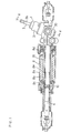
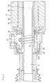
- Figure 1 is a cross-sectional view of the electric power steering device in the first embodiment of the present invention.
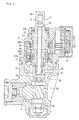
- Figure 2 is a cross-sectional view of Figure 1 along the II-II line.
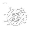
- Figure 3 is a cross-sectional view of Figure 2 along the III-III line.
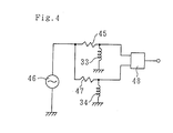
- Figure 4 is a diagram for explanation of the circuit of the torque sensor of the electric power steering device in the first embodiment of the present invention.
- Figure 5 is a cross-sectional view of the main portion of the electric power steering device in the first embodiment of the present invention.
- Figure 6 is a magnified cross-sectional view of the main portion of the electric power steering device in the first embodiment of the present invention.
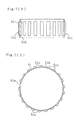
- Figure 7 (1) is a cross-sectional view of the torque setting element in the embodiments of the present invention
- Figure 7 (2) is a frontal view of the torque setting element in the embodiments of the present invention.
- Figure 8 is a diagram showing the relationship between the radial deformation of the torque setting element and the radial force in the embodiments of the present invention.
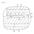
- Figure 9 is a cross-sectional view of the main portion of the electric power steering device in the second embodiment of the present invention.
- the rack pinion type electric power steering device 1 illustrated in Figures 1 and 2 comprises a steering torque transmission shaft 3 which rotates by operating a steering wheel (not illustrated), a pinion 3a formed at one end of the steering torque transmission shaft 3, and a rack 4 engaged with the pinion 3a.
- Each of the ends of the rack 4 is joined to a vehicle's wheel (not illustrated).
- the rack 4 is longitudinally shifted along the vehicle's width direction. By this shifting of the rack 4, the vehicle is steered.
- a torque sensor 7 for detecting the steering torque, a motor 8 driven according to the detected steering torque, and a screw mechanism 10 for transmitting the torque of the motor 8 to the rack 4 are provided.
- the steering torque transmission shaft 3 is supported by a housing 21 of the torque sensor 7 and a pinion housing 30 covering the pinion 3a via bearings 26, 27 and 28.
- the steering torque transmission shaft 3 is divided into a first shaft 3b, which is arranged adjacent to the steering wheel, and a second shaft 3c, which is fitted to the outer circumference of the first shaft 3b via a bush 25 so as to be rotatable relative to the first shaft 3a.
- the pinion 3a is formed around the second shaft 3c.
- a torsion bar 23 is inserted into the shafts 3a and 3c as an elastic element along the central axis of the shafts 3b and 3c.
- One end of the torsion bar 23 is joined to the first shaft 3b by a pin 22, and the other end is joined to the second shaft 3c by a pin 24.
- the first shaft 3b and the second shaft 3c are elastically rotatable relative to each other according to the steering torque.
- a portion of the outer circumference of the first shaft 3b and a portion of the inner circumference of the second shaft 3c constitute non-circular portions 3b' and 3c', which face to each other. Since the non-circular portion 3b' of the first shaft 3b and the non-circular portion 3c' of the second shaft 3c can contact with each other, the relative rotation of the two shafts 3b and 3c is restrained within a given range. Therefore, breakage of the torsion bar 23 is prevented when an excessive torque is exerted on the shaft 3.
- the torque sensor 7 has a first detection coil 33 retained by the housing 21, a second detection coil 34 retained by the housing 21, a first detection ring 36 made of a magnetic material and fixed on the outer circumference of the first shaft 3b, and a second detection ring 37 made of a magnetic material and fixed on the outer circumference of the second shaft 3c.
- One face of the first detection ring 36 and one face of the second detection ring 37 are arranged so as to be opposite to each other.
- a plurality of teeth 36a and 37a are provided along the circumferential direction.
- the outer circumference adjacent to the other face is a lesser-diameter portion 36b whose outer diameter is smaller than that of the outer circumference adjacent to the one face.
- the first detection coil 33 is arranged to surround a gap between the first detection ring 36 and the second detection ring 37.
- the second detection coil 34 is arranged to surround the first detection ring 36.
- Each of the detection coils 33 and 34 is connected to a printed board 41 attached to the housing 21 via wires.
- the printed board 41 has a signal processing circuit illustrated in Figure 4.
- the first detection coil 33 is connected to an oscillator 46 via a resistor 45
- the second detection coil 34 is connected to the oscillator 46 via a resistor 47
- each of the detection coils 33 and 34 is connected to a differential amplifier 48.
- the second detection coil 34 faces the lesser-diameter portion 36b of the first detection ring 36.
- the outer diameter of the lesser-diameter portion 36b is determined such that, the magnetic reluctance with respect to the magnetic flux generated by the second detection coil 34 and the magnetic reluctance with respect to the magnetic flux generated by the first detection coil 33 are equalize to each other when there is no steering resistance. Therefore, fluctuations of the output of the first detection coil 33 due to temperature change is canceled out by the differential amplifier 48, because it is equalized to the fluctuations of the output of the second detection coil 34 due to temperature change. Therefore, fluctuations of the detected value of the transmitted torque due to temperature change are compensated for. According to signals corresponding to the transmitted torque outputted by the differential amplifier 48, the motor 8 is driven.
- the motor 8 is provided so as to cover the rack 4 protruding from the pinion housing 30. That is, the motor 8 has a motor housing 8a attached to the pinion housing 30, a stator 8b fixed to the motor housing 8a, a cylindrical rotor (output element) 8e supported by the motor housing 8a via bearings 8c and 8d so as to be rotatable, and a magnet 8f fixed to the rotor 8e.
- the rotor 8e surrounds the rack 4.
- the screw mechanism 10 for transmitting the torque of the motor 8 to the rack 4 has a ball screw shaft 61, which is monolithically formed on the outer circumference of the rack 4, and a ball nut (rotary element) 63, which is screwed on the ball screw shaft 61 via a ball 62.
- One end of the ball nut 63 constitutes an inner ring 65a of a ball bearing 65, and is supported by a cylindrical rack cover 66 via the ball bearing 65.
- the rack cover 66 is attached to the motor housing 8a by a bolt 67.
- a torque limiter 50 is provided between the other end of the ball nut 63 and the rotor 8e.
- the torque limiter 50 has a torque setting element 51.
- the torque setting element 51 is radially deformed by being sandwiched between the outer circumference of the other end of the ball nut 63 and the inner circumference of one end of the rotor 8e.
- the diameter D1 of the outer circumference of the other end of the ball nut 63 is not greater than the diameter D2 of the inner circumference of the one end of the rotor 8e, and the torque setting element 51 is fitted into a circumferential groove 63a formed on the outer circumference of the other end of the ball nut 63.
- the torque setting element 51 comprises a metal ring body 51b having a split 51a and a plurality of semi-cylindrical projections 51c monolithically formed on the ring body 51b.
- the projections 51c are arranged along the circumferential direction at constant intervals, and radially outwardly protrudes from the ring body 51b. A radial force corresponding to the radial deformation of the projections 51c is exerted on the ball nut 63 and the rotor 8e.
- a tolerance ring made by the Rencol Tolerance Rings Company, SV type), for example, can be used.
- Figure 8 shows the relationship between the radial deformation and the radial force in the torque setting element 51.
- the radial deformation is less than a specific value ⁇ a
- the radial force increases in proportion to the radial deformation.
- the radial deformation exceeds the specific value ⁇ a, that is, in a range A in the figure
- the ratio of increase in the radial force relative to the radial deformation is smaller than that when the radial deformation is less than the specific value ⁇ a.
- the radial deformation of the torque setting element 51 is set to a value ⁇ b in the range A in which the radial deformation exceeds the specific value ⁇ a.
- the torque can be transmitted between the ball nut 63 and the rotor 8e by a frictional resistance between the torque setting element 51 and the ball nut 63 and a frictional resistance between the torque setting element 51 and the rotor 8e.
- the limit torque depends on the frictional resistance. In the present embodiment, the frictional resistance between the torque setting element 51 and the ball nut 63 is smaller than the frictional resistance between the torque setting element 51 and the rotor 8e.
- the rotation of the motor 8 can be transmitted from the rotor 8e to the ball nut 63 via the torque limiter 50, rattling during the transmission of the rotation, noise to the driver and durability reduction can be prevented. Also, even if the motor 8 is locked, fail-safe function is ensured, because the rotor 8e and the ball nut 63 can be relatively rotated via the torque limiter 50, and thus the steering operation does not become impossible. Because the torque limiter 50 can be configured simply by adding a torque setting element 51, it is possible to simplify the structure, decrease the number of parts and machining processes, and reduce production cost.
- the ratio of increase in radial force to the radial deformation of the torque setting element 51 is smaller than that at the time when the radial force increases in proportion to the radial deformation. Therefore, the variation in the radial force can be decreased even if the radial deformation of the torque setting element 51 is varied from a design value due to machining tolerance in the diametric dimensions of the rotor 8e and ball nut 63.
- the limit torque which depends on the radial force, can therefore be accurately set within a desired setting range. Therefore, the necessity of a limit torque adjusting mechanism is obviated, limit torque adjusting labor is saved, and the structure is simplified by reducing the number of parts is reduced.
- Figure 9 illustrates the second embodiment of the present invention, wherein the portions identical to those in the first embodiment are indicated by the same symbols.
- the second embodiment differs from the first embodiment, that is, the outer circumference 63' of the other end of the ball nut 63 is pressed against the inner circumference 8e' of the one end of the rotor 8e at outside the both ends of the torque setting element 51 by forcing the ball nut 63 into the rotor 8e.
- the press fit portion constitutes a torque limiter 50' together with the torque setting element 51.
- the limit torque of the torque limiter 50' corresponds to the total of the first frictional resistance corresponding to the radial deformation of the torque setting element 51 and the second frictional resistance corresponding to the force with which the ball nut 63 is forced into the rotor 8e. That is, by exerting a radial force corresponding to the radial deformation of the torque setting element 51 on the ball nut 63 and the rotor 8e, a frictional resistance between the torque setting element 51 and the ball nut 63 and also a frictional resistance between the torque setting element 51 and the rotor 8e are generated, wherein the smaller one of the two frictional resistances is the first frictional resistance.
- a second frictional resistance is generated between the ball nut 63 and the rotor 8e.
- the first frictional resistance is greater than the second frictional resistance.
- a torque can be transmitted between the ball nut 63 and the rotor 8e by the total of the first frictional resistance corresponding to the radial deformation of the torque setting element 51 and the second frictional resistance corresponding to the force with which the ball nut 63 is forced into the rotor 8e.
- the limit torque depends on the total of the first frictional resistance and the second frictional resistance.
- the frictional resistance between the torque setting element 51 and the ball nut 63 is smaller than the frictional resistance between the torque setting element 51 and the rotor 8e.
- the transmission torque is equal to the limit torque of the torque limiter 50'.
- the limit torque can be determined experimentally. By this constitution, when the transmission torque between the rotor 8e and the ball nut 63 exceeds the limit torque of the torque limiter 50', the torque setting element 51 and the ball nut 63 slip relatively and the ball nut 63 and the rotor 8e slip relatively. By these slippage, the ball nut 63 and the rotor 8e are relatively rotated.
- the limit torque can be set according to the total of the first frictional resistance corresponding to the radial deformation of the torque setting element 51 and the second frictional resistance corresponding to the press fit force with which the ball nut 63 is forced into the rotor 8e. Therefore, in this case the torque setting element 51 can be made more compact than in the case where the limit torque is set according to the first frictional resistance alone, so that the device can be made more compact in whole. Also, the press fit force can be more roughly set when the limit torque is set within a desired setting range, in comparison with the case where the limit torque is set according to the press fit force alone.
- the press fit force can be more roughly set by making the first frictional resistance greater than the second frictional resistance, which in turn makes it easier to set the limit torque within the desired setting range.
- the present invention is not limited to the above-described embodiments.
- the rotary element screwed on the rack is not limited to a ball nut, and can be a nut screwed on a trapezoidal screw formed on the outer circumference of the rack.
- the torque setting element is not limited to a tolerance ring, and can be any one, as long as it is capable of exerting a radial force corresponding to the radial deformation on the rotary element and the output element.
Landscapes
- Engineering & Computer Science (AREA)
- General Engineering & Computer Science (AREA)
- Mechanical Engineering (AREA)
- Chemical & Material Sciences (AREA)
- Combustion & Propulsion (AREA)
- Transportation (AREA)
- Power Steering Mechanism (AREA)
Claims (5)
- Elektrische Servolenkvorrichtung für ein Fahrzeug, welche folgendes aufweist:ein treibendes Rad (3a), welches sich durch die Lenkbewegung dreht;eine Zahnstange (4), welche mit dem treibenden Rad (3a) zusammenarbeitet;ein drehbares Element (63), welches auf die Zahnstange (4) geschraubt ist; undeinen Motor (8), welcher das drehbare Element (63) antreibt,wobei das Fahrzeug durch die Längsverschiebebewegung der Zahnstange (4) infolge der Drehbewegung des treibenden Rades (3a) gelenkt wird, die Lenkhilfskraft in der Längsrichtung der Zahnstange (4) durch die Drehbewegung des drehbaren Elements (63) erzeugt wird; und eine Drehmomentbegrenzungseinrichtung (50, 50') zwischen dem drehbaren Element (63) und dem Ausgangselement (8e) des Motors (8) vorgesehen ist.
- Elektrische Servolenkvorrichtung nach Anspruch 1, bei der die Drehmomentbegrenzungseinrichtung (50) ein Drehmomenteinstellelement (51) hat, welches dadurch radial verformt ist, daß es zwischen dem drehbaren Element (63) und dem Ausgangselement (8e) angeordnet ist;eine Radialkraft entsprechend der radialen Verformung des Drehmomenteinstellelements (51) auf das drehbare Element (63) und das Ausgangselement (8e) ausgeübt wird; unddie Drehmomentbegrenzung der Drehmomentbegrenzungseinrichtung (50) der radialen Verformung des Drehmomenteinstellelements (51) entspricht.
- Elektrische Servolenkvorrichtung nach Anspruch 1, bei der die Drehmomentbegrenzungseinrichtung (50') ein Drehmomenteinstellelement (51) hat, welches dadurch radial verformt ist, daß es zwischen dem drehbaren Element (63) und dem Ausgangselement (8e) angeordnet ist;eine Radialkraft entsprechend der radialen Verformung des Drehmomenteinstellelements (51) auf das drehbare Element (63) und das Ausgangselement (8e) ausgeübt wird;das drehbare Element (63) in das Ausgangselement (8e) gedrückt wird; unddie Drehmomentbegrenzung der Drehmomentbegrenzungseinrichtung (50') dem Gesamtwert aus einem ersten Reibungswiderstand, welcher der radialen Verformung des Drehmomenteinstellelements (51) entspricht, und einem zweiten Reibungswiderstand entspricht, welcher der Preßsitzkraft entspricht, mit dem das drehbare Element (63) in das Ausgangselement (8e) gedrückt wird.
- Elektrische Servolenkvorrichtung nach Anspruch 3, bei der der erste Reibungswiderstand größer als der zweite Reibungswiderstand ist.
- Elektrische Servolenkvorrichtung nach Anspruch 2, 3 oder 4, bei der das Drehmomenteinstellelement (51) eine Charakteristik dahingehend hat, daß die radiale Kraft im Verhältnis zu der radialen Verformung größer wird, wenn die radiale Verformung kleiner als ein spezifischer Wert ist, und das Zunahmeverhältnis der Radialkraft zu der radialen Verformung zu dem Zeitpunkt, wenn die radiale Verformung größer als der spezifische Wert ist, kleiner als zu dem Zeitpunkt wird, wenn die radiale Verformung unterhalb des spezifischen Werts liegt; und die radiale Verformung des Drehmomenteinstellelements (51) auf einen Wert in einem Bereich eingestellt ist, in welchem die radiale Verformung den spezifischen Wert überschreitet.
Priority Applications (1)
| Application Number | Priority Date | Filing Date | Title |
|---|---|---|---|
| DE69706371T DE69706371T3 (de) | 1996-06-19 | 1997-06-11 | Elektrische Servolenkeinrichtung |
Applications Claiming Priority (3)
| Application Number | Priority Date | Filing Date | Title |
|---|---|---|---|
| JP180018/96 | 1996-06-19 | ||
| JP18001896 | 1996-06-19 | ||
| JP18001896A JP4095124B2 (ja) | 1996-06-19 | 1996-06-19 | 電動パワーステアリング装置 |
Publications (3)
| Publication Number | Publication Date |
|---|---|
| EP0814012A1 EP0814012A1 (de) | 1997-12-29 |
| EP0814012B1 true EP0814012B1 (de) | 2001-08-29 |
| EP0814012B2 EP0814012B2 (de) | 2013-02-27 |
Family
ID=16076029
Family Applications (1)
| Application Number | Title | Priority Date | Filing Date |
|---|---|---|---|
| EP97109508A Expired - Lifetime EP0814012B2 (de) | 1996-06-19 | 1997-06-11 | Elektrische Hilfskraft-Lenkvorrichtung |
Country Status (4)
| Country | Link |
|---|---|
| US (1) | US5971094A (de) |
| EP (1) | EP0814012B2 (de) |
| JP (1) | JP4095124B2 (de) |
| DE (1) | DE69706371T3 (de) |
Cited By (4)
| Publication number | Priority date | Publication date | Assignee | Title |
|---|---|---|---|---|
| GB2343489A (en) * | 1998-06-30 | 2000-05-10 | Automotive Products Uk Ltd | Twin mass flywheel assemblies |
| EP1415890A1 (de) * | 2002-10-22 | 2004-05-06 | ZF Lenksysteme GmbH | Zahnstangen-Servolenkung für Fahrzeuge |
| DE102004023354A1 (de) * | 2004-05-12 | 2005-12-08 | Ina-Schaeffler Kg | Kugelgewindetrieb |
| DE102004023353A1 (de) * | 2004-05-12 | 2005-12-08 | Ina-Schaeffler Kg | Kugelgewindetrieb |
Families Citing this family (34)
| Publication number | Priority date | Publication date | Assignee | Title |
|---|---|---|---|---|
| JPH11139326A (ja) * | 1997-11-10 | 1999-05-25 | Koyo Seiko Co Ltd | 電動パワーステアリング装置 |
| JPH11198828A (ja) * | 1998-01-20 | 1999-07-27 | Mitsuba Corp | 電気式動力操舵装置 |
| US6244374B1 (en) * | 1998-08-21 | 2001-06-12 | Toyota Jidosha Kabushiki Kaisha | Electrically operated power steering device |
| EP1106475B1 (de) * | 1999-11-30 | 2003-03-12 | Koyo Seiko Co., Ltd. | Servolenkung |
| JP3891747B2 (ja) * | 1999-12-07 | 2007-03-14 | 株式会社ジェイテクト | 電動式舵取装置 |
| US6520274B1 (en) * | 2000-04-25 | 2003-02-18 | Visteon Global Technologies, Inc. | Modular electric steering gear assembly |
| US6805017B2 (en) * | 2000-06-19 | 2004-10-19 | Nsk Ltd. | Motor-driven power steering device |
| WO2002008047A1 (fr) * | 2000-07-21 | 2002-01-31 | Nsk Ltd. | Dispositif motorise a direction assistee |
| US7219761B2 (en) * | 2000-07-21 | 2007-05-22 | Nsk Ltd. | Motor-operated power steering apparatus |
| JP2002145080A (ja) * | 2000-11-10 | 2002-05-22 | Nsk Ltd | 電動パワーステアリング装置 |
| JP3623922B2 (ja) | 2001-02-14 | 2005-02-23 | 本田技研工業株式会社 | 電動パワーステアリング装置 |
| DE60121541T2 (de) * | 2001-03-16 | 2007-07-05 | Mando Corp., Pyungtaek | Drehmomentsensor für ein Fahrzeug |
| KR100397712B1 (ko) * | 2001-03-16 | 2003-09-13 | 주식회사 만도 | 차량용 토크센서 |
| JP4627377B2 (ja) * | 2001-03-28 | 2011-02-09 | 株式会社ショーワ | 電動パワーステアリング装置 |
| JP4773653B2 (ja) * | 2001-09-27 | 2011-09-14 | 株式会社ショーワ | 電動パワーステアリング装置 |
| FR2830912B1 (fr) * | 2001-10-15 | 2003-12-19 | Nacam | Dispositif d'accouplement en rotation de deux arbres telescopiques |
| US20050061575A1 (en) * | 2001-12-03 | 2005-03-24 | Manabu Abe | Electric power steering apparatus |
| EP1335154B1 (de) * | 2002-02-04 | 2007-01-03 | JTEKT Corporation | Elektrische Servolenkung |
| KR100816418B1 (ko) * | 2002-03-14 | 2008-03-27 | 주식회사 만도 | 랙 구동식 전동 파워스티어링 시스템 |
| ATE391066T1 (de) * | 2002-09-19 | 2008-04-15 | Nsk Ltd | Steuervorrichtung für motorisierte servolenkvorrichtung |
| DE10258826A1 (de) * | 2002-12-17 | 2004-07-15 | Ina-Schaeffler Kg | Antriebseinrichtung mit einem Wälzkörpergewindetrieb |
| DE10351484A1 (de) * | 2003-11-04 | 2005-06-09 | Zf Lenksysteme Gmbh | Elektromotor mit Überlastsicherung und damit ausgestattetes Hilfskraftlenksystem |
| JP4411952B2 (ja) | 2003-12-04 | 2010-02-10 | 株式会社ジェイテクト | 車両用操舵装置 |
| DE102004040362A1 (de) * | 2004-08-20 | 2006-02-23 | Ina-Schaeffler Kg | Kugelgewindetrieb |
| US7663274B2 (en) * | 2004-09-21 | 2010-02-16 | Nidec Corporation | Motor |
| GB0511494D0 (en) * | 2005-06-06 | 2005-07-13 | Rencol Tolerance Rings Ltd | Force limiting assembly |
| US20060278466A1 (en) * | 2005-06-13 | 2006-12-14 | Bo Cheng | Electric power steering systems |
| DE102008000213A1 (de) * | 2008-02-01 | 2009-08-06 | Zf Lenksysteme Gmbh | Elektrische Servolenkung |
| JP5326917B2 (ja) * | 2008-09-30 | 2013-10-30 | 株式会社ジェイテクト | ステアリング装置 |
| JP5332723B2 (ja) * | 2009-02-26 | 2013-11-06 | トヨタ自動車株式会社 | インターミディエイトシャフト |
| US20140260716A1 (en) * | 2013-03-12 | 2014-09-18 | Steering Solutions Ip Holding Corporation | Stop teeth for a pinion and input shaft assembly |
| DE102015112240A1 (de) * | 2015-07-28 | 2017-02-02 | Robert Bosch Automotive Steering Gmbh | Lenkung für ein kraftfahrzeug |
| CN106428189A (zh) * | 2016-11-30 | 2017-02-22 | 北汽福田汽车股份有限公司 | 用于电动助力转向系统的齿条、电动助力转向系统和车辆 |
| CN114382792A (zh) * | 2021-12-29 | 2022-04-22 | 国能铁路装备有限责任公司 | 联轴器、轴端发电装置及铁路车辆 |
Family Cites Families (14)
| Publication number | Priority date | Publication date | Assignee | Title |
|---|---|---|---|---|
| DE916370C (de) * | 1951-08-08 | 1954-08-09 | Star Kugelhalter Ges M B H Deu | UEberlastungskupplung |
| DE2018367B1 (de) † | 1970-04-16 | 1971-07-29 | Deutsche Star Kugelhalter Gmbh, 8720 Schweinfurt | Verbindungselement fur eine Kupplung mit Klemmbuchse zum Befestigen einer Nabe auf einer Welle |
| US4415054A (en) * | 1982-08-05 | 1983-11-15 | Trw Inc. | Steering gear |
| JPS6025854A (ja) * | 1983-07-22 | 1985-02-08 | Nippon Seiko Kk | 電気式動力舵取装置 |
| US4666014A (en) * | 1986-05-08 | 1987-05-19 | Trw Inc. | Floating ball-nut for an electric assist steering system |
| US4773497A (en) * | 1986-05-08 | 1988-09-27 | Trw Inc. | Floating ball-nut for an electric assist steering system |
| JPH02120178A (ja) † | 1988-10-31 | 1990-05-08 | Jidosha Kiki Co Ltd | 電動式動力舵取装置 |
| JPH05185938A (ja) † | 1991-09-30 | 1993-07-27 | Koyo Seiko Co Ltd | 電動パワーステアリング装置 |
| FR2706846B1 (de) * | 1993-06-21 | 1995-10-13 | Valeo Electronique | |
| KR0137782B1 (ko) † | 1993-12-07 | 1998-06-01 | 쭈보이 우주히꼬 | 동력타취장치 |
| US5685390A (en) * | 1994-03-17 | 1997-11-11 | Nsk, Ltd. | Electrically-operated power steering apparatus |
| US5623409A (en) * | 1994-10-31 | 1997-04-22 | Trw Inc. | Method and apparatus for non-linear damping of an electric assist steering system for vehicle yaw rate control |
| JPH08175403A (ja) * | 1994-12-21 | 1996-07-09 | Honda Motor Co Ltd | ユニット式電動パワーステアリング装置 |
| JP3411726B2 (ja) * | 1995-05-01 | 2003-06-03 | 光洋精工株式会社 | 電動パワーステアリング装置 |
-
1996
- 1996-06-19 JP JP18001896A patent/JP4095124B2/ja not_active Expired - Fee Related
-
1997
- 1997-06-09 US US08/871,844 patent/US5971094A/en not_active Expired - Lifetime
- 1997-06-11 EP EP97109508A patent/EP0814012B2/de not_active Expired - Lifetime
- 1997-06-11 DE DE69706371T patent/DE69706371T3/de not_active Expired - Lifetime
Cited By (7)
| Publication number | Priority date | Publication date | Assignee | Title |
|---|---|---|---|---|
| GB2343489A (en) * | 1998-06-30 | 2000-05-10 | Automotive Products Uk Ltd | Twin mass flywheel assemblies |
| US6378678B1 (en) * | 1998-06-30 | 2002-04-30 | Automotive Products Uk, Ltd | Twin mass flywheel assemblies |
| GB2343489B (en) * | 1998-06-30 | 2003-02-05 | Automotive Products Uk Ltd | Twin mass flywheel assemblies |
| EP1415890A1 (de) * | 2002-10-22 | 2004-05-06 | ZF Lenksysteme GmbH | Zahnstangen-Servolenkung für Fahrzeuge |
| DE102004023354A1 (de) * | 2004-05-12 | 2005-12-08 | Ina-Schaeffler Kg | Kugelgewindetrieb |
| DE102004023353A1 (de) * | 2004-05-12 | 2005-12-08 | Ina-Schaeffler Kg | Kugelgewindetrieb |
| US7210369B2 (en) | 2004-05-12 | 2007-05-01 | Ina-Schaeffler Kg | Ball screw drive |
Also Published As
| Publication number | Publication date |
|---|---|
| DE69706371T3 (de) | 2013-04-25 |
| DE69706371D1 (de) | 2001-10-04 |
| EP0814012A1 (de) | 1997-12-29 |
| JPH107005A (ja) | 1998-01-13 |
| DE69706371T2 (de) | 2002-02-07 |
| EP0814012B2 (de) | 2013-02-27 |
| JP4095124B2 (ja) | 2008-06-04 |
| US5971094A (en) | 1999-10-26 |
Similar Documents
| Publication | Publication Date | Title |
|---|---|---|
| EP0814012B1 (de) | Elektrische Hilfskraft-Lenkvorrichtung | |
| US5819871A (en) | Electric power steering device | |
| US7014009B2 (en) | Motor operated power steering device | |
| EP1714851B1 (de) | Elektrische servolenkvorrichtung | |
| EP1288106B1 (de) | Elektrische Servolenkung mit Diebstahl-Schutzfunktion und deren Herstellung | |
| JP3604460B2 (ja) | 電動パワーステアリング装置 | |
| JP3587614B2 (ja) | 電動パワーステアリング装置 | |
| JP3579509B2 (ja) | トルクリミッタおよび電動パワーステアリング装置 | |
| JP2001158368A (ja) | 電動式パワーステアリング装置 | |
| JP3645688B2 (ja) | ラックピニオン式ステアリング装置 | |
| JP3328719B2 (ja) | 動力舵取装置 | |
| JP2001138932A (ja) | 電動式パワーステアリング装置 | |
| JP3681866B2 (ja) | 電動パワーステアリング装置 | |
| JP3713346B2 (ja) | 電動パワーステアリング装置 | |
| JPH10129511A (ja) | 電動パワーステアリング装置 | |
| JP3769136B2 (ja) | 電動パワーステアリング装置 | |
| JP3810940B2 (ja) | 電動パワーステアリング装置 | |
| JP3047934B2 (ja) | トルク検出装置 | |
| JP2005280589A (ja) | 電動パワーステアリング装置 | |
| JPH0532231U (ja) | パワーステアリング装置 |
Legal Events
| Date | Code | Title | Description |
|---|---|---|---|
| PUAI | Public reference made under article 153(3) epc to a published international application that has entered the european phase |
Free format text: ORIGINAL CODE: 0009012 |
|
| AK | Designated contracting states |
Kind code of ref document: A1 Designated state(s): AT BE CH DE DK ES FI FR GB GR IE IT LI LU MC NL PT SE |
|
| 17P | Request for examination filed |
Effective date: 19971113 |
|
| AKX | Designation fees paid | ||
| RBV | Designated contracting states (corrected) | ||
| GRAG | Despatch of communication of intention to grant |
Free format text: ORIGINAL CODE: EPIDOS AGRA |
|
| GRAG | Despatch of communication of intention to grant |
Free format text: ORIGINAL CODE: EPIDOS AGRA |
|
| GRAH | Despatch of communication of intention to grant a patent |
Free format text: ORIGINAL CODE: EPIDOS IGRA |
|
| 17Q | First examination report despatched |
Effective date: 20010116 |
|
| GRAH | Despatch of communication of intention to grant a patent |
Free format text: ORIGINAL CODE: EPIDOS IGRA |
|
| GRAA | (expected) grant |
Free format text: ORIGINAL CODE: 0009210 |
|
| AK | Designated contracting states |
Kind code of ref document: B1 Designated state(s): DE FR GB IT |
|
| REF | Corresponds to: |
Ref document number: 69706371 Country of ref document: DE Date of ref document: 20011004 |
|
| ET | Fr: translation filed | ||
| REG | Reference to a national code |
Ref country code: GB Ref legal event code: IF02 |
|
| PLAV | Examination of admissibility of opposition |
Free format text: ORIGINAL CODE: EPIDOS OPEX |
|
| PLBQ | Unpublished change to opponent data |
Free format text: ORIGINAL CODE: EPIDOS OPPO |
|
| PLBI | Opposition filed |
Free format text: ORIGINAL CODE: 0009260 |
|
| PLBF | Reply of patent proprietor to notice(s) of opposition |
Free format text: ORIGINAL CODE: EPIDOS OBSO |
|
| 26 | Opposition filed |
Opponent name: LILLESHALL PLASTICS & ENGINEERING LIMITED Effective date: 20020528 |
|
| PLAV | Examination of admissibility of opposition |
Free format text: ORIGINAL CODE: EPIDOS OPEX |
|
| PLBF | Reply of patent proprietor to notice(s) of opposition |
Free format text: ORIGINAL CODE: EPIDOS OBSO |
|
| PLBF | Reply of patent proprietor to notice(s) of opposition |
Free format text: ORIGINAL CODE: EPIDOS OBSO |
|
| PLBF | Reply of patent proprietor to notice(s) of opposition |
Free format text: ORIGINAL CODE: EPIDOS OBSO |
|
| RAP2 | Party data changed (patent owner data changed or rights of a patent transferred) |
Owner name: JTEKT CORPORATION |
|
| APBM | Appeal reference recorded |
Free format text: ORIGINAL CODE: EPIDOSNREFNO |
|
| APBP | Date of receipt of notice of appeal recorded |
Free format text: ORIGINAL CODE: EPIDOSNNOA2O |
|
| APAH | Appeal reference modified |
Free format text: ORIGINAL CODE: EPIDOSCREFNO |
|
| APBQ | Date of receipt of statement of grounds of appeal recorded |
Free format text: ORIGINAL CODE: EPIDOSNNOA3O |
|
| PLAB | Opposition data, opponent's data or that of the opponent's representative modified |
Free format text: ORIGINAL CODE: 0009299OPPO |
|
| R26 | Opposition filed (corrected) |
Opponent name: SAINT-GOBAIN PERFORMANCE PLASTICS RENCOL LTD Effective date: 20020528 |
|
| PGFP | Annual fee paid to national office [announced via postgrant information from national office to epo] |
Ref country code: IT Payment date: 20100619 Year of fee payment: 14 |
|
| PGFP | Annual fee paid to national office [announced via postgrant information from national office to epo] |
Ref country code: GB Payment date: 20100609 Year of fee payment: 14 |
|
| GBPC | Gb: european patent ceased through non-payment of renewal fee |
Effective date: 20110611 |
|
| PG25 | Lapsed in a contracting state [announced via postgrant information from national office to epo] |
Ref country code: IT Free format text: LAPSE BECAUSE OF NON-PAYMENT OF DUE FEES Effective date: 20110611 |
|
| APBU | Appeal procedure closed |
Free format text: ORIGINAL CODE: EPIDOSNNOA9O |
|
| PG25 | Lapsed in a contracting state [announced via postgrant information from national office to epo] |
Ref country code: GB Free format text: LAPSE BECAUSE OF NON-PAYMENT OF DUE FEES Effective date: 20110611 |
|
| REG | Reference to a national code |
Ref country code: DE Ref legal event code: R082 Ref document number: 69706371 Country of ref document: DE Representative=s name: BERENDT UND KOLLEGEN, DE |
|
| PUAH | Patent maintained in amended form |
Free format text: ORIGINAL CODE: 0009272 |
|
| STAA | Information on the status of an ep patent application or granted ep patent |
Free format text: STATUS: PATENT MAINTAINED AS AMENDED |
|
| 27A | Patent maintained in amended form |
Effective date: 20130227 |
|
| AK | Designated contracting states |
Kind code of ref document: B2 Designated state(s): DE FR GB IT |
|
| REG | Reference to a national code |
Ref country code: DE Ref legal event code: R102 Ref document number: 69706371 Country of ref document: DE |
|
| REG | Reference to a national code |
Ref country code: DE Ref legal event code: R082 Ref document number: 69706371 Country of ref document: DE Representative=s name: BERENDT UND KOLLEGEN, DE Effective date: 20130114 Ref country code: DE Ref legal event code: R081 Ref document number: 69706371 Country of ref document: DE Owner name: JTEKT CORPORATION, JP Free format text: FORMER OWNER: KOYO SEIKO CO., LTD., OSAKA, JP Effective date: 20130114 |
|
| REG | Reference to a national code |
Ref country code: DE Ref legal event code: R102 Ref document number: 69706371 Country of ref document: DE Effective date: 20130227 |
|
| REG | Reference to a national code |
Ref country code: FR Ref legal event code: PLFP Year of fee payment: 20 |
|
| PGFP | Annual fee paid to national office [announced via postgrant information from national office to epo] |
Ref country code: DE Payment date: 20160607 Year of fee payment: 20 |
|
| PGFP | Annual fee paid to national office [announced via postgrant information from national office to epo] |
Ref country code: FR Payment date: 20160516 Year of fee payment: 20 |
|
| REG | Reference to a national code |
Ref country code: DE Ref legal event code: R071 Ref document number: 69706371 Country of ref document: DE |