EP0813228A1 - Plasma-Massenspektrometer - Google Patents
Plasma-Massenspektrometer Download PDFInfo
- Publication number
- EP0813228A1 EP0813228A1 EP97303703A EP97303703A EP0813228A1 EP 0813228 A1 EP0813228 A1 EP 0813228A1 EP 97303703 A EP97303703 A EP 97303703A EP 97303703 A EP97303703 A EP 97303703A EP 0813228 A1 EP0813228 A1 EP 0813228A1
- Authority
- EP
- European Patent Office
- Prior art keywords
- ions
- ion
- mass
- guiding means
- potential
- Prior art date
- Legal status (The legal status is an assumption and is not a legal conclusion. Google has not performed a legal analysis and makes no representation as to the accuracy of the status listed.)
- Granted
Links
Images


Classifications
-
- H—ELECTRICITY
- H01—ELECTRIC ELEMENTS
- H01J—ELECTRIC DISCHARGE TUBES OR DISCHARGE LAMPS
- H01J49/00—Particle spectrometers or separator tubes
- H01J49/02—Details
- H01J49/06—Electron- or ion-optical arrangements
- H01J49/062—Ion guides
- H01J49/063—Multipole ion guides, e.g. quadrupoles, hexapoles
-
- H—ELECTRICITY
- H01—ELECTRIC ELEMENTS
- H01J—ELECTRIC DISCHARGE TUBES OR DISCHARGE LAMPS
- H01J49/00—Particle spectrometers or separator tubes
- H01J49/02—Details
- H01J49/04—Arrangements for introducing or extracting samples to be analysed, e.g. vacuum locks; Arrangements for external adjustment of electron- or ion-optical components
- H01J49/0468—Arrangements for introducing or extracting samples to be analysed, e.g. vacuum locks; Arrangements for external adjustment of electron- or ion-optical components with means for heating or cooling the sample
- H01J49/0481—Arrangements for introducing or extracting samples to be analysed, e.g. vacuum locks; Arrangements for external adjustment of electron- or ion-optical components with means for heating or cooling the sample with means for collisional cooling
-
- H—ELECTRICITY
- H01—ELECTRIC ELEMENTS
- H01J—ELECTRIC DISCHARGE TUBES OR DISCHARGE LAMPS
- H01J49/00—Particle spectrometers or separator tubes
- H01J49/02—Details
- H01J49/10—Ion sources; Ion guns
- H01J49/105—Ion sources; Ion guns using high-frequency excitation, e.g. microwave excitation, Inductively Coupled Plasma [ICP]
Definitions
- This invention relates to a plasma (inductively-coupled or microwave induced) mass spectrometer, and in particular to such a spectrometer intended for the determination of isotopic ratios.
- interfering ion signals comprise atomic or molecular ions such as Ar + , Ar ++ , ArH + , ArN + etc. which are generated by the plasma in the absence of any introduced sample, and also molecular ions such as oxides, argides and hydride ions formed by reaction of the elements present in a sample with other species present in the sample.
- interfering ions mask the signals from atomic ions for which a measurement is required because they have the same mass-to-charge ratio as that of an atomic ion to be measured, but they also result in a very high total ion current, much greater than that typically available from a sample.
- the maximum ion current that can be transmitted through any ion-optical system is generally limited by space-charge effects, and in practice the high ion current due to these unwanted species can saturate the spectrometer optics, reducing the number of sample ions transmitted and causing other undesirable effects such as mass discrimination and matrix effects.
- An RF-only quadrupole was disposed between the nozzle-skimmer interface and the mass-analyzing quadrupole of an otherwise conventional ICP mass spectrometer, and a collision gas, (typically xenon) was introduced into it at a pressure between 10 -5 and 10 -4 torr. It was hoped that this would induce dissociation of unwanted polyatomic species before they entered the mass analyzer by a mechanism similar to the collisional dissociation of molecular ions used in the triple quadrupole mass spectrometers intended for use in organic mass spectrometry.
- a collision gas typically xenon
- this approach is obviously highly specific and while reducing the effect of one interfering ion may introduce another that was not previously present.
- the method is dependent on chemical reaction between the added hydrogen and the unwanted ions, and similar reactions may take place between the hydrogen and the atomic ions to be determined, albeit at a much slower rate, generating unwanted mass discrimination effects and additional molecular ions. Because the removal of ions is a chemical process, Eiden, et al, do not teach that any gas other than hydrogen could be used.
- WO 95/23018 teaches a variety of multipolar ion guides for transporting ions through one or more pressure reduction stages between the ion source and the mass analyzer of a mass spectrometer. These rod sets extend from a first region maintained at a first pressure into a second region maintained at a second pressure.
- the multipolar rod sets may comprise 4,6, or 8 electrodes and the pressure in the space inside them may be in the range taught by US 4963736, at least along part of their length.
- WO 95/23018 also suggests that its multipolar rod sets may be used in conjunction with an ICP source, but does not teach the use of a rod set whose entrance and exit are disposed in the same region and maintained at substantially the same pressure.
- plasma mass spectrometer is used to describe mass spectrometers having either microwave-induced (MIP) or inductively-coupled (ICP) plasma ion sources operating substantially at atmospheric pressure, and the word “plasma” means either an ICP, MIP, or glow discharge.
- MIP microwave-induced
- ICP inductively-coupled
- a mass spectrometer comprising:
- helium is introduced into said ion guiding means.
- At least a portion of said ion guiding means is surrounded by gas containment means disposed wholly within said first evacuated chamber and disposed so that both the entrance and exit of the ion guiding means are outside of it. Said inert gas may then be introduced into said containment means. In this way a partial pressure of at least 10 -3 torr can be maintained in at least a portion of the ion guiding means while its entrance and exit are maintained at a lower pressure (typically that of the first evacuated chamber).
- the gas containment means is shorter than the ion guiding means and is disposed so that its longitudinal centre is closer to the entrance of the guiding means than to the exit.
- the length of the gas containment means may be 50% or less of the length of the ion guiding means.
- the inert gas should be introduced into the gas containment means so that the highest partial pressure of inert gas in the ion guiding means is located between its entrance and a point half-way along its length. A point about one-third of the length from the entrance is most preferred. The best results are obtained when the gas containment means is disposed with one end just downstream of the entrance of the ion guiding means.
- the gas containment means should be such that a partial pressure of at least 10 -3 torr of inert gas can be maintained within it while the pressure in the first evacuated chamber is maintained at less than 10 -4 torr.
- the inventors have found that it is particularly advantageous to maintain the pressure at the exit of the guiding means as low as possible, and this is facilitated by use of a gas containment means which is shorter than the guiding means and is located towards the entrance, rather than the exit, of the guiding means.
- the ion guiding means preferably comprises a hexapole rod set, but quadrupole or octupole sets may be used instead. It has been found that a hexapole set results in only a minimal variation in ion transmission efficiency with mass-to-charge ratio, which is especially important if isotopic ratios are to be determined.
- the length of the rod set is between 20 and 100 times greater than the radius of the elongate space between the rods, and most preferably about 50 times.
- the elongate rods may conveniently be of constant diameter and be disposed parallel to one another, but the use of electrode rods which are tapered and/or not parallel to each other is also within the scope of the invention.
- an axial potential gradient may be provided along the ion guiding means which can assist ion transmission. This can be done, for example, by providing an ion guiding means which comprises a plurality of multipole rod sets disposed one after the other, with each portion having a different axial potential, or by splitting the gas containment means which surrounds the ion guiding means into several segments insulated from one another and applying different DC potentials to the segments, but other methods are also possible.
- rods comprising the ion guiding means are preferably supplied only with an AC voltage, it is also within the scope of the invention to add a DC potential in the manner conventional for quadrupole mass analysers, particularly if a quadrupole arrangement is employed.
- the first axis (of the nozzle-skimmer interface means) does not pass through and the aperture in the diaphragm, so that there exists no line-of-sight path along the first axis to the aperture.
- the ion-guiding means is disposed so that the second axis is inclined to the first axis so that ions leaving the nozzle-skimmer interface means enter the elongate space in the guiding means and are guided by the ion confining action of the guiding means to the aperture. In this way neutral molecules or atoms are prevented from passing into the aperture and into the ion mass-to-charge analyzing means and background signals can be minimised.
- a further reduction in background can be obtained by arranging the entrance axis of the mass analyzer (which receives the ions from the ion guiding means which have passed through the aperture in the diaphragm means) to be inclined relative to the second axis (of the ion guiding means).
- the second axis of the ion guiding means
- the first and entrance axes can be arranged parallel to one another, which facilitates the construction of an instrument.
- the ion mass-to-charge analyzing means comprises a magnetic sector mass analyzer.
- the analyzer may be fitted with a plurality of ion collectors disposed along its image focal plane so that ions of several different mass-to-charge ratios can be measured simultaneously.
- Such multi-collector systems are conventional in magnetic sector isotope ratio mass spectrometers.
- the inventors have found that it is unnecessary to use a double-focussing mass analyzer (i.e., one incorporating an electrostatic ion-energy analyzer) for this purpose because the mass resolution and abundance sensitivity of a spectrometer according to the invention is very much greater than that of a prior single-focusing plasma spectrometer with a comparable magnetic sector analyzer, but if very high resolution is required, a double-focusing analyzer could be used.
- a double-focussing mass analyzer i.e., one incorporating an electrostatic ion-energy analyzer
- the ion mass-to-charge ratio analyzer may comprise a quadrupole mass analyzer.
- a quadrupole mass analyzer provides an ICP mass spectrometer which is capable of analyzing atomic species which yield ions at mass-to-charge ratios where significant interferences occur with prior quadrupole instruments without the expense of a high resolution mass analyzer.
- the ion mass-to-charge ratio analyzer may comprise a time-of-flight analyzer, particularly one having an orthogonal disposition of the entrance axis and the ion drift direction. Such an instrument typically exhibits greater sensitivity than a quadrupole based instrument.
- the invention provides a method of mass spectrometric analysis of a sample comprising the following steps carried out sequentially:
- the invention therefore further provides a method as previously defined wherein the step of mass analyzing said ions comprises the use of a quadrupole mass analyser having a central axis and the step of guiding said ions comprises passing ions through ion guiding means having a central axis, said method further comprising the step of maintaining a potential difference between the potential of the central axis of said ion guiding means and the potential of the central axis of said quadrupole mass analyser such that the transmission of polyatomic ions is reduced relative to that of atomic ions.
- the invention provides a method as previously defined wherein the step of mass analyzing said ions comprises the use of a quadrupole ion-trap mass analyser having a centre and the step of guiding said ions comprises passing ions through ion guiding means having a central axis, said method further comprising the step of maintaining a potential difference between the potential of the central axis of said ion guiding means and the potential at the centre of said quadrupole ion-trap mass analyser such that the transmission of polyatomic ions is reduced relative to that of atomic ions.
- the invention provides a method of reducing molecular ion interferences in plasma mass spectroscopy carried out in a spectrometer as defined above. Typically this potential difference is in the range 0 ⁇ 1 volt and is critical to a few tenths of a volt.
- electrostatic lens means are provided between the nozzle-skimmer interface and the entrance of the ion-guiding means.
- this lens means is maintained at a potential of between 600 and 1000 volts negative (in the case of positive ions) relative to the potential of the nozzle-skimmer interface and the ion guiding means.
- the electrode comprises a hollow conical structure disposed with its apex closest to the skimmer.
- the lens electrode may also serve as a second diaphragm to define an additional evacuated chamber and therefore provide an additional stage of differential pumping between the nozzle-skimmer interface and the ion-guiding means.
- the potential applied to the electrostatic lens means is adjusted to improve the transmission efficiency of ions from the nozzle-skimmer interface to the ion guiding means.
- the inventors have found that when the potential is correctly set, the lens means increases the transmission efficiency by more than a factor of 100, particularly of the ions of low mass-to-charge ratio which in its absence are most likely to be lost because of space-charge effects in the vicinity of the skimmer. It has also been found that the provision of the lens reduces the transmission of ions such as ArO + , consequently improving the detection sensitivity for Fe. Use of this lens also greatly reduces mass discrimination in the nozzle-skimmer interface region, which is especially valuable when isotopic ratios are to be determined.
- samples to be analyzed may be introduced into the plasma in the form of an aerosol generated by a conventional nebulizer.
- the inventors have found that best results are obtained when samples are in the form of aqueous solutions.
- the addition of small amounts (less than 5%, and most preferably less than 1%) of another material to the inert gas can further enhance performance.
- the addition of 0.5% of xenon to a helium inert gas surprisingly has been found to further reduce the intensity of oxygenated molecular ions, and approximately 0.5% of hydrogen or water can result in a further reduction of ions such as Ar + .
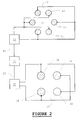
- a spectrometer comprises a plasma torch 1 which generates a plasma 2.
- Energy for generating the plasma is inductively coupled from RF current flowing in a coil (not shown) surrounding the torch 1, as in a conventional ICP mass spectrometer.
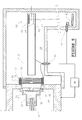
- the torch is disposed so that the plasma 2 is directed towards and is adjacent to a sampling cone 3 which is mounted on a water-cooled housing 4.
- a skimmer 5 is disposed downstream of the sampling cone 3 and the region 6 between the cone 3 and the skimmer 5 is evacuated by a mechanical vacuum pump (not shown) connected to the port 7 so that the pressure in the region 6 can be maintained at about 2 torr.
- the cone 3 and skimmer 5 comprise a nozzle-skimmer interface through axially aligned apertures in which ions may pass from the plasma 2 into an evacuated region 8 in which the pressure is maintained at approximately 10 -2 torr by means of a turbomolecular pump (not shown) connected to the port 9. Ions passing through the aperture in skimmer 5 then pass through an aperture in an electrostatic lens element 10 of hollow conical form which also serves to divide the evacuated region 8 from a first evacuated chamber 11 in which the pressure is maintained at about 10 -3 torr by another turbomolecular pump (not shown) connected to the port 25.
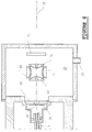
- Ion guiding means generally indicated by 12 are disposed in the first evacuated chamber 11 and comprise a multipole rod set of 6 elongate parallel electrode rods (3 of which are identified at 13, 14, and 15) disposed symmetrically around a second axis 16 to form a hexapole structure.
- the electrode rods are secured in position by three circular support insulators 72, 73, and 74, two of which (72 and 74) also locate the ion guiding means in the housing of the first evacuated chamber 11, as shown.
- An elongate space 17 (figure 2) extends longitudinally through the rods about the axis 16.
- An RF power supply 26 (figure 2) provides an AC voltage between the rods which are connected as shown.
- the second axis 16 of the rod set is inclined to the first axis 27 of the nozzle-skimmer interface (which passes through the apertures in the sampling cone 3 and the skimmer 5) as shown in figure 1.
- a diaphragm means comprising a tapered electrode 18 having an aperture 19 is provided to divide the evacuated chamber 11 from a second evacuated chamber 20, and the end of the ion guiding means 12 is disposed so that ions travelling through it exit through the aperture 19. Because of the inclination of the axis 16, the aperture 19 is of course displaced from the axis of the nozzle-skimmer interface.
- a conventional quadrupole mass analyzer comprising a quadrupole mass filter and ion detector shown schematically at 29 and 33 respectively is disposed in the second evacuated chamber 20.
- the filter 29 comprises four electrodes 30 which are supported in insulators 31 in a conventional manner.
- the entrance axis 32 of the mass filter 29 is inclined to the second axis 16 of the ion guiding means 12, as shown in the figure, in order to further reduce the transmission of neutral particles from the plasma 2 into the filter 29. Ions leaving the exit of the ion guiding means 12 are deflected in a field generated by a suitable potential applied to the tapered electrode 18 (which is mounted on an insulated flange 34), so that they pass along the entrance axis 32 of the filter 29.
- a conventional quadrupole mass filter power supply 35 is connected to the four electrodes 30 as shown in figure 2 to enable mass filtering of the ions entering along the axis 32.
- the power supply 35 has a bias input 37, the potential on which determines the potential of the central axis of the array of rods 30.
- Input 37 is connected to an adjustable voltage source 36 (see below).
- An AC-only power supply 26 feeds the electrodes comprising the ion guiding means 12, as shown in figure 2.
- Power supply 26 has a bias input 43, the potential on which controls the potential of the axis of ion guiding means, connected to the adjustable voltage source 36.
- Source 36 maintains a potential difference between the axial potentials of the ion guiding means and the mass filter, which potential difference is adjusted as described previously to increase the ratio of wanted atomic to unwanted polyatomic ions entering the mass filter.
- the potential difference is typically in the range 0 ⁇ 1 volts, dependent on the polarity of the ions, and must be carefully set and maintained at the selected value throughout the analysis, as previously explained.
- FIG. 4 An alternative embodiment of the invention comprising a magnetic sector analyzer (generally indicated by 38) in place of a quadrupole mass analyzer is shown in figure 4.
- the magnetic sector analyzer is shown in simplified form as it is essentially of conventional known design.
- ions passing through the aperture 19 in the tapered electrode 18 are deflected along the entrance axis 32 by the field resulting from a potential difference maintained between the electrode 18 and the central axis of the ion guiding means 12.
- This potential difference is typically between 1 and 5 volts positive (for positive ions), but is not as critical as the corresponding potential in the previous embodiment.
- Electrode 50 is the entrance aperture of the magnetic sector analyzer 38 and is maintained at the accelerating potential of the analyzer (-6KV), relative to the grounded housing of the second evacuated chamber 20 by an accelerating voltage supply 48.
- the other electrodes are supplied by adjustable potential dividers connected between the electrode 50 and the grounded housing.
- Typical potentials on electrodes 44, 45, 46, and 49 are -600 volts, -1500 volts, -3000 volts and -4000 volts respectively.
- Electrodes 45 and 49 comprise two "half" electrodes between which a small adjustable potential difference can be applied to steer the ion beam in the "y" and "z" directions, respectively.
- Ions leaving the electrode 50 enter the flight tube 39 of the analyzer 38 with 6KeV energy and are dispersed according to their mass-to-charge rations by a magnetic field generated between the poles 40 of an electromagnet. Because the ions enter the magnetic field at a potential of -6KV, the flight tube 39 is mounted on insulating flanges 47 and 51 and is maintained at the potential of electrode 50. The ion detector system 41 is also maintained at the potential of electrode 50. The high voltage supply leads to electrode 50 and the detector 41 pass through high-voltage feedthroughs 52 and 53 in the wall of the chamber 20 and the detector housing 42, as shown.
- the inventors have found that with the figure 4 apparatus a considerable improvement in mass resolution and abundance sensitivity is achieved in comparison with a similar ICP spectrometer in which the ion guiding means 12 is omitted.
- the apparatus of figure 4 is therefore well-suited to the determination of isotopic ratios, particularly when the ion detector system 41 is of the multi-collector type allowing the simultaneous detection of the isotopes to be monitored. Good isotopic ratio accuracy may then be achieved without the additional complication of a double-focussing mass analyzer, although the use of such an analyzer in place of the magnetic sector analyzer alone shown in figure 4 is within the scope of the invention.
- FIG. 5 illustrates how a time-of-flight (TOF) mass analyzer may be used in the invention.
- TOF time-of-flight
- the TOF analyzer generally indicated by 63 is shown only in outline form.
- ions pass through the aperture 19 in the tapered electrode 18 to travel along the entrance axis 32, exactly as described in the figure 4 embodiment.
- the 5 electrodes 54-58 which are supported on the insulator assemblies 60. These electrodes are similar in function to the electrodes 44, 45, 46, 49 and 50 in the figure 4 embodiment, and the final electrode 58 is maintained at typically -2.5KV (for positive ions) by the power supply 48 (connected to it via the feedthrough 61) relative to the grounded housing of the chamber 20. Ions therefore enter the electrostatic screening tube 59 (maintained at the same potential as electrode 58) with 2.5KeV energy to the pulse-out region of the TOF analyzer 63.
- the TOF analyzer is a conventional orthogonal type in which bunches of ions travelling along the axis 32 are orthogonally ejected along the drift axis 67 towards the ion detector system 41 by application of suitable electrical pulses to the electrodes 64,65 and 66.
- Ion detector system 41 is of course also maintained at the potential of electrode 58 via a connection to the feedthrough 62.
- An electrostatic screening tube similar to the tube 59 may also be provided to screen the ions travelling along the drift axis 67 from the grounded vacuum enclosure of the drift region of the TOF analyzer. The operation of such a TOF spectrometer is known in the art and need not be described further.
- FIG. 6 An embodiment of the invention using a quadrupole ion-trap mass analyzer generally indicated by 71 is shown in figure 6.
- the detailed construction and operation of the analyzer 71 which comprises a ring electrode 68 and two end-cap electrodes 69 and 70, is conventional and need not be described in detail.
- the analyzer 71 is merely disposed to receive ions passing through the aperture 19 in a similar manner to the quadrupole analyzer 29 shown in figure 3.
- the potential at the centre of the trap is maintained at ⁇ 1 volt relative to the axial potential of the guiding means, exactly as in the case of the quadrupole analyzer.
- the six rod electrodes exemplified at 13-15 are enclosed along the front portion of their length (about half the total length) by gas containment means comprising a tube 21 which contains the support insulators 73 and 74 for the rods themselves.
- An inert qas is introduced into the tube 21 via an inlet pipe 22 so that the pressure in the elongate space 17 in the centre of the rods is at least 10 -3 torr.
- the inlet pipe 22 is disposed so that the gas enters the ion-guiding means about one-quarter of its length from the entrance.
- the support insulators 73 and 74 are disposed close to the ends 23 and 24, respectively, of the tube 21 and are of relatively gas-tight construction (save for a central aperture through which the ions pass) so that a pressure differential of at least a factor of 10 can be maintained between the elongate space 17 and the first evacuated region 11. It would, however, be possible but less effective to supply the inert gas directly to the chamber 11 around the ion guiding means 12, particularly in an arrangement in which there is no tube 21, provided the pressure in the space 17 is maintained at at least 10 -3 torr.
- helium is introduced into the tube 21, but other gases such as argon can also be used.
- Nitrogen is also effective and has the advantage of being cheap, but tends to cause a higher background spectrum.
- the exact pressure in the elongate space 17 required to bring about the advantages of the invention has not been measured, but in practice the flow of helium is gradually increased while observing the resultant mass spectrum until the intensity of the interfering peaks begins to decrease, and may be then further increased until no further reduction is obtained or the intensity of wanted atomic ions begins to decrease.
- the AC applied to the rods is at a frequency of 5 MHz at a voltage of between 100 and 400 volts. Because in practice it is found that the maximum transmission of the hexapole for ions of different mass-to-charge ratios occurs at different voltages, the AC voltage is conveniently scanned in synchronism with the mass-to-charge ratio scanning of the mass analyzer to ensure that maximum transmission through the hexapole of the ions actually being detected is achieved.
- a potential difference of about 1 volt is maintained between the potential of the central axis 16 of the ion-guiding means 12 and the axial or centre potential of the quadrupole mass analyzer.
- This potential difference provides a potential barrier which positive ions emerging from the ion guiding means 12 must surmount by virtue of their kinetic energy before they can pass through the aperture 19 and into the mass analyzer.
- the kinetic energy of the ions is changed substantially to the thermal energy of the inert gas molecules introduced into the ion guiding means, so that the typical energy spread of 1 to 20 eV of ions generated in the plasma is greatly reduced.
- molecular ions and atomic ions emerge from the guiding means with different kinetic energies, so that careful adjustment of the potential difference can further reduce the number of polyatomic ions which reach the mass analyzer.
- a voltage of between -600 and -1000 volts is applied to the electrode 10 by a suitable power supply (not shown) to provide a degree of focusing action.
- This helps to increase the ion transmission by reducing the loss of ions (especially of low mass-to-charge ratio) on the inside surface of the skimmer 5. (Ions having low mass-to-charge ratios will tend to be on the outside of the material expanding from the aperture of the skimmer for gas kinetic reasons). In practice, the transmission of these low mass ions can be increased by a factor of about 100 by adjustment of the potential on the electrode 10.
- the presence of the electrode 10 also reduces intensity of molecular ions such as ArO + , so that the potential on the electrode 10 can be adjusted also to minimise the intensity of these interfering ions.
- the minimum in the intensity of the ArO + ions typically occurs at the same voltage which maximises transmission of the low mass ions, perhaps indicating that the optimum potential is that which minimises the contact of the ions with the inside surface of the skimmer 5.
- Samples may be introduced into the plasma by any of the means conventionally employed in ICP or MIP mass spectrometry.
- the inventors have observed that the most significant improvements, particularly in respect of the suppression of Ar + ions, are obtained when samples are introduced in the form of aqueous solutions through a conventional type of nebulizer. It appears, therefore, that the material introduced into the plasma may play an as yet undefined role in the imperfectly understood mechanism by which the advantages of the invention are produced.
Landscapes
- Chemical & Material Sciences (AREA)
- Analytical Chemistry (AREA)
- Physics & Mathematics (AREA)
- Engineering & Computer Science (AREA)
- Plasma & Fusion (AREA)
- Other Investigation Or Analysis Of Materials By Electrical Means (AREA)
- Electron Tubes For Measurement (AREA)
Priority Applications (1)
| Application Number | Priority Date | Filing Date | Title |
|---|---|---|---|
| EP01204795A EP1246225B1 (de) | 1996-06-10 | 1997-05-30 | Plasmamassenspektrometer |
Applications Claiming Priority (2)
| Application Number | Priority Date | Filing Date | Title |
|---|---|---|---|
| GBGB9612070.4A GB9612070D0 (en) | 1996-06-10 | 1996-06-10 | Plasma mass spectrometer |
| GB9612070 | 1996-06-10 |
Related Child Applications (1)
| Application Number | Title | Priority Date | Filing Date |
|---|---|---|---|
| EP01204795A Division EP1246225B1 (de) | 1996-06-10 | 1997-05-30 | Plasmamassenspektrometer |
Publications (2)
| Publication Number | Publication Date |
|---|---|
| EP0813228A1 true EP0813228A1 (de) | 1997-12-17 |
| EP0813228B1 EP0813228B1 (de) | 2002-07-31 |
Family
ID=10795023
Family Applications (2)
| Application Number | Title | Priority Date | Filing Date |
|---|---|---|---|
| EP97303703A Expired - Lifetime EP0813228B1 (de) | 1996-06-10 | 1997-05-30 | Plasma-Massenspektrometer |
| EP01204795A Expired - Lifetime EP1246225B1 (de) | 1996-06-10 | 1997-05-30 | Plasmamassenspektrometer |
Family Applications After (1)
| Application Number | Title | Priority Date | Filing Date |
|---|---|---|---|
| EP01204795A Expired - Lifetime EP1246225B1 (de) | 1996-06-10 | 1997-05-30 | Plasmamassenspektrometer |
Country Status (7)
| Country | Link |
|---|---|
| US (3) | US6222185B1 (de) |
| EP (2) | EP0813228B1 (de) |
| JP (1) | JP3493460B2 (de) |
| AU (1) | AU713008C (de) |
| CA (1) | CA2206667C (de) |
| DE (3) | DE69740125D1 (de) |
| GB (1) | GB9612070D0 (de) |
Cited By (20)
| Publication number | Priority date | Publication date | Assignee | Title |
|---|---|---|---|---|
| EP0878828A1 (de) * | 1997-05-16 | 1998-11-18 | Mingda Wang | Hochdruckionenquelle für ein zweidimensionales Radiofrequenzquadrupolmassenspektrometer |
| WO1998056030A1 (en) * | 1997-06-04 | 1998-12-10 | Mds Inc. | Bandpass reactive collison cell |
| WO1999059187A1 (en) * | 1998-05-14 | 1999-11-18 | Varian Inc | Ion trap mass spectrometer with electrospray ionization |
| WO1999066536A2 (en) * | 1998-06-15 | 1999-12-23 | Battelle Memorial Institute | An apparatus for reduction of selected ion intensities in confined ion beams |
| GB2341270A (en) * | 1998-09-02 | 2000-03-08 | Shimadzu Corp | Mass spectrometer having ion lens composed of plurality of virtual rods comprising plurality of electrodes |
| WO2000016375A1 (en) * | 1998-09-16 | 2000-03-23 | Unicam Limited | Means for removing unwanted ions from an ion transport system and mass spectrometer |
| WO2001051917A2 (en) * | 2000-01-10 | 2001-07-19 | Mds Inc. | An apparatus for and method of discriminating against unwanted ionized species in mass spectrometry with collision and reaction devices |
| WO2003077280A1 (en) * | 2002-03-08 | 2003-09-18 | Varian Australia Pty Ltd | A plasma mass spectrometer |
| EP1580791A3 (de) * | 2004-03-11 | 2006-10-25 | Shimadzu Corporation | Massenspektrometer |
| USRE40632E1 (en) | 1999-12-03 | 2009-02-03 | Thermo Finnigan Llc. | Mass spectrometer system including a double ion guide interface and method of operation |
| CN104380089A (zh) * | 2012-03-16 | 2015-02-25 | 布鲁克化学分析有限公司 | 一种用于质谱仪器的改进接口 |
| USRE45553E1 (en) | 2002-05-13 | 2015-06-09 | Thermo Fisher Scientific Inc. | Mass spectrometer and mass filters therefor |
| DE102016103292A1 (de) | 2015-02-26 | 2016-09-01 | Nu Instruments Limited | Massenspektrometer |
| DE102016009789A1 (de) | 2015-08-14 | 2017-02-16 | Thermo Fisher Scientific (Bremen) Gmbh | Spiegellinse zum Richten eines Ionenstrahls |
| DE102016121127A1 (de) | 2015-11-17 | 2017-05-18 | Thermo Fisher Scientific (Bremen) Gmbh | Zugabe von reaktiven Spezies zur ICP-Quelle in einem Massenspektrometer |
| DE112016003713T5 (de) | 2015-08-14 | 2018-05-03 | Thermo Fisher Scientific (Bremen) Gmbh | Ein axiales Feld aufweisende Kollisionszelle |
| DE112016003705T5 (de) | 2015-08-14 | 2018-05-09 | Thermo Fisher Scientific (Bremen) Gmbh | Multidetektor-Massenspektrometer und -spektrometrieverfahren |
| DE102017127189A1 (de) | 2016-12-19 | 2018-06-21 | Thermo Fisher Scientific (Bremen) Gmbh | Bestimmung von isobaren Interferenzen in einem Massenspektrometer |
| GB2560160A (en) * | 2017-02-23 | 2018-09-05 | Thermo Fisher Scient Bremen Gmbh | Methods in mass spectrometry using collision gas as ion source |
| GB2568178A (en) * | 2017-02-23 | 2019-05-08 | Thermo Fisher Scient Bremen Gmbh | Methods in mass spectrometry using collision gas as ion source |
Families Citing this family (31)
| Publication number | Priority date | Publication date | Assignee | Title |
|---|---|---|---|---|
| GB9612070D0 (en) * | 1996-06-10 | 1996-08-14 | Micromass Ltd | Plasma mass spectrometer |
| JP3904322B2 (ja) * | 1998-04-20 | 2007-04-11 | 株式会社日立製作所 | 分析装置 |
| JP2002015699A (ja) * | 2000-06-28 | 2002-01-18 | Shimadzu Corp | イオンガイドおよびこれを用いた質量分析装置 |
| AUPQ861500A0 (en) * | 2000-07-06 | 2000-08-03 | Varian Australia Pty Ltd | Plasma source for spectrometry |
| US6576897B1 (en) * | 2000-09-13 | 2003-06-10 | Varian, Inc. | Lens-free ion collision cell |
| US6627912B2 (en) * | 2001-05-14 | 2003-09-30 | Mds Inc. | Method of operating a mass spectrometer to suppress unwanted ions |
| JP4569049B2 (ja) * | 2001-06-06 | 2010-10-27 | 株式会社島津製作所 | 質量分析装置 |
| DE10297199T5 (de) * | 2001-09-10 | 2004-08-12 | Varian Australia Pty. Ltd., Mulgrave | Vorrichtung und Verfahren zur Elementaren Massenspektrometrie |
| AU2002328668B2 (en) * | 2001-09-10 | 2006-09-28 | Agilent Technologies Australia (M) Pty Ltd | Apparatus and method for elemental mass spectrometry |
| US6914242B2 (en) | 2002-12-06 | 2005-07-05 | Agilent Technologies, Inc. | Time of flight ion trap tandem mass spectrometer system |
| WO2004083805A2 (en) * | 2003-03-19 | 2004-09-30 | Thermo Finnigan Llc | Obtaining tandem mass spectrometry data for multiple parent ions in an ion population |
| GB0514964D0 (en) * | 2005-07-21 | 2005-08-24 | Ms Horizons Ltd | Mass spectrometer devices & methods of performing mass spectrometry |
| US7424980B2 (en) * | 2004-04-08 | 2008-09-16 | Bristol-Myers Squibb Company | Nano-electrospray nebulizer |
| DE102004037511B4 (de) * | 2004-08-03 | 2007-08-23 | Bruker Daltonik Gmbh | Multipole durch Drahterosion |
| GB0427634D0 (en) * | 2004-12-17 | 2005-01-19 | Micromass Ltd | Mass spectrometer |
| WO2007090282A1 (en) * | 2006-02-08 | 2007-08-16 | Mds Analytical Technologies, A Business Unit Of Mds Inc., Doing Business Through Its Sciex Division | Radio frequency ion guide |
| JP5341753B2 (ja) | 2006-07-10 | 2013-11-13 | マイクロマス ユーケー リミテッド | 質量分析計 |
| US7927329B2 (en) * | 2006-09-28 | 2011-04-19 | Covidien Ag | Temperature sensing return electrode pad |
| US8507850B2 (en) * | 2007-05-31 | 2013-08-13 | Perkinelmer Health Sciences, Inc. | Multipole ion guide interface for reduced background noise in mass spectrometry |
| US8334506B2 (en) | 2007-12-10 | 2012-12-18 | 1St Detect Corporation | End cap voltage control of ion traps |
| US20090194679A1 (en) * | 2008-01-31 | 2009-08-06 | Agilent Technologies, Inc. | Methods and apparatus for reducing noise in mass spectrometry |
| US7973277B2 (en) | 2008-05-27 | 2011-07-05 | 1St Detect Corporation | Driving a mass spectrometer ion trap or mass filter |
| GB2484488B (en) * | 2010-10-12 | 2013-04-17 | Vg Systems Ltd | Improvements in and relating to ion guns |
| JP5792561B2 (ja) * | 2011-08-25 | 2015-10-14 | 株式会社日立製作所 | 自動クリーニング機能付き質量分析装置 |
| US8378293B1 (en) | 2011-09-09 | 2013-02-19 | Agilent Technologies, Inc. | In-situ conditioning in mass spectrometer systems |
| US20140138533A1 (en) * | 2012-11-19 | 2014-05-22 | Canon Kabushiki Kaisha | Ion mass selector, ion irradiation device, surface analysis device, and ion mass selecting method |
| GB201519830D0 (en) * | 2015-11-10 | 2015-12-23 | Micromass Ltd | A method of transmitting ions through an aperture |
| GB2549248B (en) | 2016-01-12 | 2020-07-22 | Thermo Fisher Scient Bremen Gmbh | IRMS sample introduction system and method |
| WO2019011175A1 (zh) | 2017-07-12 | 2019-01-17 | 赵晓峰 | 一种存储和传输正负离子的装置和方法 |
| US10580632B2 (en) | 2017-12-18 | 2020-03-03 | Agilent Technologies, Inc. | In-situ conditioning in mass spectrometry systems |
| CN114242560A (zh) * | 2021-11-02 | 2022-03-25 | 中国原子能科学研究院 | 一种用于排除同量异位素的激光光解装置及方法 |
Citations (4)
| Publication number | Priority date | Publication date | Assignee | Title |
|---|---|---|---|---|
| US4328420A (en) * | 1980-07-28 | 1982-05-04 | French John B | Tandem mass spectrometer with open structure AC-only rod sections, and method of operating a mass spectrometer system |
| US4746794A (en) * | 1985-10-24 | 1988-05-24 | Mds Health Group Limited | Mass analyzer system with reduced drift |
| WO1995023018A1 (en) * | 1994-02-28 | 1995-08-31 | Analytica Of Branford, Inc. | Multipole ion guide for mass spectrometry |
| WO1997025737A1 (en) | 1996-01-05 | 1997-07-17 | Battelle Memorial Institute | A method for reduction of selected ion intensities in confined ion beams |
Family Cites Families (15)
| Publication number | Priority date | Publication date | Assignee | Title |
|---|---|---|---|---|
| US4234791A (en) * | 1978-11-13 | 1980-11-18 | Research Corporation | Tandem quadrupole mass spectrometer for selected ion fragmentation studies and low energy collision induced dissociator therefor |
| US4963735A (en) * | 1988-11-11 | 1990-10-16 | Hitachi, Ltd. | Plasma source mass spectrometer |
| CA1307859C (en) | 1988-12-12 | 1992-09-22 | Donald James Douglas | Mass spectrometer and method with improved ion transmission |
| JP2543761B2 (ja) * | 1989-03-23 | 1996-10-16 | セイコー電子工業株式会社 | 誘導結合プラズマ質量分析装置 |
| GB9110960D0 (en) * | 1991-05-21 | 1991-07-10 | Logicflit Limited | Mass spectrometer |
| DE4202123C2 (de) | 1992-01-27 | 1995-04-06 | Bruker Franzen Analytik Gmbh | Vorrichtung für die massenspektrometrische Untersuchung schneller organischer Ionen |
| US5248875A (en) | 1992-04-24 | 1993-09-28 | Mds Health Group Limited | Method for increased resolution in tandem mass spectrometry |
| US5381008A (en) | 1993-05-11 | 1995-01-10 | Mds Health Group Ltd. | Method of plasma mass analysis with reduced space charge effects |
| JP3367719B2 (ja) | 1993-09-20 | 2003-01-20 | 株式会社日立製作所 | 質量分析計および静電レンズ |
| JP3404849B2 (ja) | 1993-12-29 | 2003-05-12 | 株式会社島津製作所 | Ms/ms型質量分析装置 |
| JPH0836989A (ja) | 1994-07-26 | 1996-02-06 | Shimadzu Corp | 四重極型ms/ms質量分析装置 |
| DE19520319A1 (de) * | 1995-06-02 | 1996-12-12 | Bruker Franzen Analytik Gmbh | Verfahren und Vorrichtung für die Einführung von Ionen in Quadrupol-Ionenfallen |
| US5576540A (en) * | 1995-08-11 | 1996-11-19 | Mds Health Group Limited | Mass spectrometer with radial ejection |
| US5672868A (en) * | 1996-02-16 | 1997-09-30 | Varian Associates, Inc. | Mass spectrometer system and method for transporting and analyzing ions |
| GB9612070D0 (en) * | 1996-06-10 | 1996-08-14 | Micromass Ltd | Plasma mass spectrometer |
-
1996
- 1996-06-10 GB GBGB9612070.4A patent/GB9612070D0/en active Pending
-
1997
- 1997-05-30 DE DE69740125T patent/DE69740125D1/de not_active Expired - Lifetime
- 1997-05-30 AU AU23702/97A patent/AU713008C/en not_active Ceased
- 1997-05-30 DE DE69714356T patent/DE69714356T2/de not_active Expired - Lifetime
- 1997-05-30 US US08/866,524 patent/US6222185B1/en not_active Expired - Lifetime
- 1997-05-30 EP EP97303703A patent/EP0813228B1/de not_active Expired - Lifetime
- 1997-05-30 CA CA002206667A patent/CA2206667C/en not_active Expired - Fee Related
- 1997-05-30 DE DE0813228T patent/DE813228T1/de active Pending
- 1997-05-30 EP EP01204795A patent/EP1246225B1/de not_active Expired - Lifetime
- 1997-06-02 JP JP15922697A patent/JP3493460B2/ja not_active Expired - Fee Related
-
2001
- 2001-03-14 US US09/805,062 patent/US6545270B2/en not_active Expired - Lifetime
-
2003
- 2003-03-14 US US10/387,417 patent/US6707032B2/en not_active Expired - Lifetime
Patent Citations (4)
| Publication number | Priority date | Publication date | Assignee | Title |
|---|---|---|---|---|
| US4328420A (en) * | 1980-07-28 | 1982-05-04 | French John B | Tandem mass spectrometer with open structure AC-only rod sections, and method of operating a mass spectrometer system |
| US4746794A (en) * | 1985-10-24 | 1988-05-24 | Mds Health Group Limited | Mass analyzer system with reduced drift |
| WO1995023018A1 (en) * | 1994-02-28 | 1995-08-31 | Analytica Of Branford, Inc. | Multipole ion guide for mass spectrometry |
| WO1997025737A1 (en) | 1996-01-05 | 1997-07-17 | Battelle Memorial Institute | A method for reduction of selected ion intensities in confined ion beams |
Non-Patent Citations (7)
| Title |
|---|
| D. J. DOUGLAS: "Collisional focusing effects in radio frequency quadrupoles.", JOURNAL OF THE AMERICAN SOCIETY FOR MASS SPECTROMETRY., vol. 2, 1992, USA, pages 398 - 408, XP002041216 * |
| D. J. DOUGLAS: "Some current perspectives on ICP-MS.", CANADIAN JOURNAL OF SPECTROSCOPY, vol. 34, no. 2, 1989, CA, pages 38 - 49, XP002041215 * |
| D.J.DOUGLAS, J.B.FRENCH: "Collisional Focusing Effects in Radio Frequency Quadrupoles", JOURNAL AMERICAN SOCIETY FOR MASS SPECTROMETRY, vol. 3, 1992, ONTARIO, CANADA, pages 398 - 408, XP000667302 |
| F.L. KING ET AL.: "Collision-induced dissociation of polyatomic ions in glow discharge mass spectrometry", INTERNATIONAL JOURNAL OF MASS SPECTROMETRY AND ION PROCESSES., vol. 89, 1989, AMSTERDAM NL, pages 171 - 185, XP002041214 * |
| G.C. EIDEN: "Selective removal of plasma matrix ions in plasma source mass spectrometry", JOURNAL OF ANALYTICAL ATOMIC SPECTROMETRY, vol. 11, no. 4, 1996, UK, pages 317 - 322, XP002041213 * |
| G.C.EIDEN ET AL: "Selective Removal of Plasma Matrix Ions in Plasma Source Mass Spectrometry", JOURNAL OF ANALITICAL STOMIC SPECTROMETRY, vol. 11, April 1996 (1996-04-01), RICHLAND, WASHINGTON, USA, pages 317 - 322, XP000667301 |
| J. T. ROWAN ET AL.: "Attenuation of polyatomic ion interferences in inductively coupled plasma mass spectrometry by gas-phase collisions", APPLIED SPECTROMETRY, vol. 43, no. 6, 1989, pages 976 - 980, XP000032932 * |
Cited By (41)
| Publication number | Priority date | Publication date | Assignee | Title |
|---|---|---|---|---|
| US6259091B1 (en) | 1996-01-05 | 2001-07-10 | Battelle Memorial Institute | Apparatus for reduction of selected ion intensities in confined ion beams |
| US5942752A (en) * | 1996-05-17 | 1999-08-24 | Hewlett-Packard Company | Higher pressure ion source for two dimensional radio-frequency quadrupole electric field for mass spectrometer |
| EP0878828A1 (de) * | 1997-05-16 | 1998-11-18 | Mingda Wang | Hochdruckionenquelle für ein zweidimensionales Radiofrequenzquadrupolmassenspektrometer |
| WO1998056030A1 (en) * | 1997-06-04 | 1998-12-10 | Mds Inc. | Bandpass reactive collison cell |
| WO1999059187A1 (en) * | 1998-05-14 | 1999-11-18 | Varian Inc | Ion trap mass spectrometer with electrospray ionization |
| WO1999066536A2 (en) * | 1998-06-15 | 1999-12-23 | Battelle Memorial Institute | An apparatus for reduction of selected ion intensities in confined ion beams |
| WO1999066536A3 (en) * | 1998-06-15 | 2000-02-03 | Battelle Memorial Institute | An apparatus for reduction of selected ion intensities in confined ion beams |
| GB2341270A (en) * | 1998-09-02 | 2000-03-08 | Shimadzu Corp | Mass spectrometer having ion lens composed of plurality of virtual rods comprising plurality of electrodes |
| US6462338B1 (en) | 1998-09-02 | 2002-10-08 | Shimadzu Corporation | Mass spectrometer |
| DE19941670B4 (de) * | 1998-09-02 | 2009-11-26 | Shimadzu Corp. | Massenspektrometer und Verfahren zum Betreiben eines Massenspektrometers |
| WO2000016375A1 (en) * | 1998-09-16 | 2000-03-23 | Unicam Limited | Means for removing unwanted ions from an ion transport system and mass spectrometer |
| USRE45386E1 (en) | 1998-09-16 | 2015-02-24 | Thermo Fisher Scientific (Bremen) Gmbh | Means for removing unwanted ions from an ion transport system and mass spectrometer |
| EP2801999A1 (de) | 1998-09-16 | 2014-11-12 | Thermo Fisher Scientific (Bremen) GmbH | Mittel zum Entfernen von ungewünschten Ionen aus einem Ionentransportsystem und Massenspektrometer |
| EP2204842A1 (de) * | 1998-09-16 | 2010-07-07 | Thermo Fisher Scientific (Bremen) GmbH | Vorrichtung zur Entfernung unerwünschter Ionen aus einem Ionenleiter und aus einem Massenspektrometer |
| EP2204841A1 (de) * | 1998-09-16 | 2010-07-07 | Thermo Fisher Scientific (Bremen) GmbH | Vorrichtung zur Entfernung unerwünschter Ionen aus einem Ionenleiter und aus einem Massenspektrometer |
| US7202470B1 (en) | 1998-09-16 | 2007-04-10 | Thermo Fisher Scientific Inc. | Means for removing unwanted ions from an ion transport system and mass spectrometer |
| US7230232B2 (en) | 1998-09-16 | 2007-06-12 | Thermo Fisher Scientific (Bremen) Gmbh | Means for removing unwanted ions from an ion transport system and mass spectrometer |
| USRE40632E1 (en) | 1999-12-03 | 2009-02-03 | Thermo Finnigan Llc. | Mass spectrometer system including a double ion guide interface and method of operation |
| WO2001051917A3 (en) * | 2000-01-10 | 2002-04-04 | Mds Inc | An apparatus for and method of discriminating against unwanted ionized species in mass spectrometry with collision and reaction devices |
| WO2001051917A2 (en) * | 2000-01-10 | 2001-07-19 | Mds Inc. | An apparatus for and method of discriminating against unwanted ionized species in mass spectrometry with collision and reaction devices |
| US7119330B2 (en) | 2002-03-08 | 2006-10-10 | Varian Australia Pty Ltd | Plasma mass spectrometer |
| WO2003077280A1 (en) * | 2002-03-08 | 2003-09-18 | Varian Australia Pty Ltd | A plasma mass spectrometer |
| USRE45553E1 (en) | 2002-05-13 | 2015-06-09 | Thermo Fisher Scientific Inc. | Mass spectrometer and mass filters therefor |
| US7230237B2 (en) | 2004-03-11 | 2007-06-12 | Shimadzu Corporation | Mass spectrometer |
| EP1580791A3 (de) * | 2004-03-11 | 2006-10-25 | Shimadzu Corporation | Massenspektrometer |
| CN104380089A (zh) * | 2012-03-16 | 2015-02-25 | 布鲁克化学分析有限公司 | 一种用于质谱仪器的改进接口 |
| DE102016103292A1 (de) | 2015-02-26 | 2016-09-01 | Nu Instruments Limited | Massenspektrometer |
| DE102016103292B4 (de) | 2015-02-26 | 2023-08-10 | Nu Instruments Limited | Massenspektrometer |
| DE112016003713T5 (de) | 2015-08-14 | 2018-05-03 | Thermo Fisher Scientific (Bremen) Gmbh | Ein axiales Feld aufweisende Kollisionszelle |
| DE112016003705T5 (de) | 2015-08-14 | 2018-05-09 | Thermo Fisher Scientific (Bremen) Gmbh | Multidetektor-Massenspektrometer und -spektrometrieverfahren |
| US10867780B2 (en) | 2015-08-14 | 2020-12-15 | Thermo Fisher Scientific (Bremen) Gmbh | Multi detector mass spectrometer and spectrometry method filter |
| DE102016009789A1 (de) | 2015-08-14 | 2017-02-16 | Thermo Fisher Scientific (Bremen) Gmbh | Spiegellinse zum Richten eines Ionenstrahls |
| DE102016121127A1 (de) | 2015-11-17 | 2017-05-18 | Thermo Fisher Scientific (Bremen) Gmbh | Zugabe von reaktiven Spezies zur ICP-Quelle in einem Massenspektrometer |
| DE102017127189A1 (de) | 2016-12-19 | 2018-06-21 | Thermo Fisher Scientific (Bremen) Gmbh | Bestimmung von isobaren Interferenzen in einem Massenspektrometer |
| DE102017127189B4 (de) | 2016-12-19 | 2023-11-09 | Thermo Fisher Scientific (Bremen) Gmbh | Bestimmung von isobaren Interferenzen in einem Massenspektrometer |
| GB2560160A (en) * | 2017-02-23 | 2018-09-05 | Thermo Fisher Scient Bremen Gmbh | Methods in mass spectrometry using collision gas as ion source |
| GB2568178A (en) * | 2017-02-23 | 2019-05-08 | Thermo Fisher Scient Bremen Gmbh | Methods in mass spectrometry using collision gas as ion source |
| GB2568178B (en) * | 2017-02-23 | 2020-09-02 | Thermo Fisher Scient (Bremen) Gmbh | Methods in mass spectrometry using collision gas as ion source |
| GB2560160B (en) * | 2017-02-23 | 2021-08-18 | Thermo Fisher Scient Bremen Gmbh | Methods in mass spectrometry using collision gas as ion source |
| US11328915B2 (en) | 2017-02-23 | 2022-05-10 | Thermo Fisher Scientific (Bremen) Gmbh | Methods in mass spectrometry using collision gas as ion source |
| DE102018010478B3 (de) | 2017-02-23 | 2023-04-27 | Thermo Fisher Scientific (Bremen) Gmbh | Verfahren in der massenspektrometrie unter verwendung von kollisionsgas als ionenquelle |
Also Published As
| Publication number | Publication date |
|---|---|
| CA2206667A1 (en) | 1997-12-10 |
| DE69740125D1 (de) | 2011-03-31 |
| AU2370297A (en) | 1997-12-18 |
| JP3493460B2 (ja) | 2004-02-03 |
| AU713008B2 (en) | 1999-11-18 |
| US20010010354A1 (en) | 2001-08-02 |
| DE69714356D1 (de) | 2002-09-05 |
| US6707032B2 (en) | 2004-03-16 |
| GB9612070D0 (en) | 1996-08-14 |
| US6222185B1 (en) | 2001-04-24 |
| AU713008C (en) | 2003-09-18 |
| CA2206667C (en) | 2001-04-17 |
| EP1246225B1 (de) | 2011-02-16 |
| US20030160168A1 (en) | 2003-08-28 |
| DE813228T1 (de) | 1998-06-25 |
| JPH10188879A (ja) | 1998-07-21 |
| EP0813228B1 (de) | 2002-07-31 |
| US6545270B2 (en) | 2003-04-08 |
| EP1246225A1 (de) | 2002-10-02 |
| DE69714356T2 (de) | 2002-11-21 |
Similar Documents
| Publication | Publication Date | Title |
|---|---|---|
| CA2206667C (en) | Plasma mass spectrometer | |
| US7259379B2 (en) | On-axis electron impact ion source | |
| EP1114437B1 (de) | Vorrichtung zur entfernung unerwünschteter ionen aus einem ionenleiter und aus einem massenspektrometer | |
| US8299421B2 (en) | Low-pressure electron ionization and chemical ionization for mass spectrometry | |
| EP1051731B1 (de) | Verfahren zur untersuchung von ionen in einem apparat mit einem flugzeit-spektrometer und einer linearen quadrupol-ionenfalle | |
| JP4331398B2 (ja) | パルスイオン源及びイオン運動を制動するための輸送デバイスを備えた分析計並びにその使用方法 | |
| EP0407539B2 (de) | Plasma-massen-spektrometer | |
| US20010020679A1 (en) | Tandem mass spectrometer comprising only two quadrupole filters | |
| US8525106B2 (en) | Method and apparatus for transmitting ions in a mass spectrometer maintained in a sub-atmospheric pressure regime | |
| CA2626383A1 (en) | Mass spectrometry with multipole ion guides | |
| US6194717B1 (en) | Quadrupole mass analyzer and method of operation in RF only mode to reduce background signal | |
| US20180114684A1 (en) | Ion Current On-Off Switching Method and Device | |
| US7935922B2 (en) | Ion guide chamber | |
| EP1027720B1 (de) | Verfahren zum betrieb eines massenspektrometers mit einem eingangssignal niedriger auflösung zur verbesserung des signal / rausch -verhältnisses | |
| EP3627534B1 (de) | Ionendetektionsvorrichtung und massenspektrometer | |
| GB2301704A (en) | Introducing ions into a high-vacuum chamber, e.g. of a mass spectrometer | |
| US20240162024A1 (en) | A system for production of high yield of ions in rf only confinement field for use in mass spectrometry | |
| CA2206557A1 (en) | Use of an off-axis ion path for background reduction of an rf-only quadrupole mass analyzer |
Legal Events
| Date | Code | Title | Description |
|---|---|---|---|
| PUAI | Public reference made under article 153(3) epc to a published international application that has entered the european phase |
Free format text: ORIGINAL CODE: 0009012 |
|
| AK | Designated contracting states |
Kind code of ref document: A1 Designated state(s): BE DE FR GB IT NL SE |
|
| 17P | Request for examination filed |
Effective date: 19971205 |
|
| EL | Fr: translation of claims filed | ||
| DET | De: translation of patent claims | ||
| AKX | Designation fees paid |
Free format text: BE DE FR GB IT NL SE |
|
| RBV | Designated contracting states (corrected) |
Designated state(s): BE DE FR GB IT NL SE |
|
| TPAD | Observations filed by third parties |
Free format text: ORIGINAL CODE: EPIDOS TIPA |
|
| 17Q | First examination report despatched |
Effective date: 19991230 |
|
| GRAG | Despatch of communication of intention to grant |
Free format text: ORIGINAL CODE: EPIDOS AGRA |
|
| GRAG | Despatch of communication of intention to grant |
Free format text: ORIGINAL CODE: EPIDOS AGRA |
|
| GRAH | Despatch of communication of intention to grant a patent |
Free format text: ORIGINAL CODE: EPIDOS IGRA |
|
| RIN1 | Information on inventor provided before grant (corrected) |
Inventor name: JARVIS, STUART ALAN Inventor name: MERREN, THOMAS OLIVER Inventor name: TURNER, PATRICK JAMES Inventor name: HAINES, RAYMOND CLIVE Inventor name: SPEAKMAN, JAMES |
|
| GRAH | Despatch of communication of intention to grant a patent |
Free format text: ORIGINAL CODE: EPIDOS IGRA |
|
| GRAA | (expected) grant |
Free format text: ORIGINAL CODE: 0009210 |
|
| AK | Designated contracting states |
Kind code of ref document: B1 Designated state(s): BE DE FR GB IT NL SE |
|
| PG25 | Lapsed in a contracting state [announced via postgrant information from national office to epo] |
Ref country code: NL Free format text: LAPSE BECAUSE OF FAILURE TO SUBMIT A TRANSLATION OF THE DESCRIPTION OR TO PAY THE FEE WITHIN THE PRESCRIBED TIME-LIMIT Effective date: 20020731 Ref country code: FR Free format text: LAPSE BECAUSE OF NON-PAYMENT OF DUE FEES Effective date: 20020731 Ref country code: BE Free format text: LAPSE BECAUSE OF FAILURE TO SUBMIT A TRANSLATION OF THE DESCRIPTION OR TO PAY THE FEE WITHIN THE PRESCRIBED TIME-LIMIT Effective date: 20020731 |
|
| REG | Reference to a national code |
Ref country code: GB Ref legal event code: FG4D |
|
| REF | Corresponds to: |
Ref document number: 69714356 Country of ref document: DE Date of ref document: 20020905 |
|
| PG25 | Lapsed in a contracting state [announced via postgrant information from national office to epo] |
Ref country code: SE Free format text: LAPSE BECAUSE OF FAILURE TO SUBMIT A TRANSLATION OF THE DESCRIPTION OR TO PAY THE FEE WITHIN THE PRESCRIBED TIME-LIMIT Effective date: 20021031 |
|
| NLV1 | Nl: lapsed or annulled due to failure to fulfill the requirements of art. 29p and 29m of the patents act | ||
| PLBE | No opposition filed within time limit |
Free format text: ORIGINAL CODE: 0009261 |
|
| STAA | Information on the status of an ep patent application or granted ep patent |
Free format text: STATUS: NO OPPOSITION FILED WITHIN TIME LIMIT |
|
| REG | Reference to a national code |
Ref country code: GB Ref legal event code: 732E |
|
| 26N | No opposition filed |
Effective date: 20030506 |
|
| PGFP | Annual fee paid to national office [announced via postgrant information from national office to epo] |
Ref country code: IT Payment date: 20130524 Year of fee payment: 17 |
|
| PGFP | Annual fee paid to national office [announced via postgrant information from national office to epo] |
Ref country code: DE Payment date: 20140529 Year of fee payment: 18 |
|
| PG25 | Lapsed in a contracting state [announced via postgrant information from national office to epo] |
Ref country code: IT Free format text: LAPSE BECAUSE OF NON-PAYMENT OF DUE FEES Effective date: 20140530 |
|
| REG | Reference to a national code |
Ref country code: DE Ref legal event code: R119 Ref document number: 69714356 Country of ref document: DE |
|
| PG25 | Lapsed in a contracting state [announced via postgrant information from national office to epo] |
Ref country code: DE Free format text: LAPSE BECAUSE OF NON-PAYMENT OF DUE FEES Effective date: 20151201 |
|
| PGFP | Annual fee paid to national office [announced via postgrant information from national office to epo] |
Ref country code: GB Payment date: 20160527 Year of fee payment: 20 |
|
| REG | Reference to a national code |
Ref country code: GB Ref legal event code: PE20 Expiry date: 20170529 |
|
| PG25 | Lapsed in a contracting state [announced via postgrant information from national office to epo] |
Ref country code: GB Free format text: LAPSE BECAUSE OF EXPIRATION OF PROTECTION Effective date: 20170529 |