EP0812972B1 - Serrure électrique pour ouvrant de véhicule automobile - Google Patents
Serrure électrique pour ouvrant de véhicule automobile Download PDFInfo
- Publication number
- EP0812972B1 EP0812972B1 EP97401069A EP97401069A EP0812972B1 EP 0812972 B1 EP0812972 B1 EP 0812972B1 EP 97401069 A EP97401069 A EP 97401069A EP 97401069 A EP97401069 A EP 97401069A EP 0812972 B1 EP0812972 B1 EP 0812972B1
- Authority
- EP
- European Patent Office
- Prior art keywords
- bolt
- driver
- lock
- catch
- fact
- Prior art date
- Legal status (The legal status is an assumption and is not a legal conclusion. Google has not performed a legal analysis and makes no representation as to the accuracy of the status listed.)
- Expired - Lifetime
Links
- 210000003323 beak Anatomy 0.000 description 4
- 230000000694 effects Effects 0.000 description 2
- 230000035939 shock Effects 0.000 description 2
- 239000006096 absorbing agent Substances 0.000 description 1
- 210000002445 nipple Anatomy 0.000 description 1
- 210000000056 organ Anatomy 0.000 description 1
- 230000000284 resting effect Effects 0.000 description 1
- 230000000717 retained effect Effects 0.000 description 1
Images


Classifications
-
- E—FIXED CONSTRUCTIONS
- E05—LOCKS; KEYS; WINDOW OR DOOR FITTINGS; SAFES
- E05B—LOCKS; ACCESSORIES THEREFOR; HANDCUFFS
- E05B81/00—Power-actuated vehicle locks
- E05B81/12—Power-actuated vehicle locks characterised by the function or purpose of the powered actuators
- E05B81/14—Power-actuated vehicle locks characterised by the function or purpose of the powered actuators operating on bolt detents, e.g. for unlatching the bolt
Definitions
- the invention relates to an electric lock for opening motor vehicle and, in particular, for vehicle door automobile.
- the locks of sashes of motor vehicles frequently have a fork-shaped swivel bolt and a ratchet subjected to an elastic return which pushes it towards the bolt, said ratchet capable of cooperating with at least one notch of the bolt to prevent a rotation of said bolt, the bolt of said lock cooperating with a keeper secured to the body, the bolt fork being positioned on the relative path of the strike when the door is brought in closed position so that the strike makes the latch pivot to a position in which the pawl prevents pivoting reverse of the bolt, the strike being then positioned in the fork of the bolt.
- This type of lock can be controlled manually by a rod system that connects a lock lever, for example the ratchet, to an interior or exterior operating handle.
- the present invention therefore relates to a lock electric of the type defined above, characterized in that the (or a of) crankpin (s) carried by the rotary element driven by the motor electric can cooperate with a likely trainer, in a movement against an elastic return, to rotate the ratchet to release the bolt for the opening of the lock, the rotary member continuing to rotate at least until the coach escapes the action of the crank pin and being associated with a means engine stop, which stops its rotation when the coach has escaped the action of the crankpin, said coach comprising, in its zone of cooperation with the crankpin (s), a V-shaped recess into which (or one of) the crankpin (s) can penetrate to generate a pivoting around a fixed axis of the coach, which itself, in this movement carried out against its elastic return, spreads the ratchet from its bolt retaining position.
- the rotary element is driven by a motor at a single direction of rotation and carries two crank pins symmetrical with respect to its axis.
- the coach and the pawl are integral with one another.
- the coach consists of two levers integral in rotation, one constituting a lever opening which can act on the pawl to cause it to pivot, while the other constitutes a control lever which carries the recess cooperating with (or one of) the crankpin (s).
- the coach can be a lever having, seen in plan, the shape of a boot, the recess corresponding to the hollow, which exists between the sole part and the part heel of the boot, the pivot articulation of said lever being effected at its opposite end to that which carries the sole and heel parts of the boot ;
- the engine stopping means can be constituted, in the first place, by mechanical abutment, against the sole part of the coach, that of the two crankpins of the rotary element which has not, during the opening of the lock which has just been carried out, caused the pivoting of the coach and, secondly, by a cut of the power supply to the motor, which only intervenes after the stop mechanical of the crankpin against the coach.
- the pawl in the open position of the lock, the pawl leans against a edge of the bolt and, when the lock reaches the closed position, the pawl coming to cooperate with a notch of the bolt under the action of its elastic return, the trainer and the ratchet rotate by a sufficient angle so that the crankpin, which was at the right of the sole part of the coach, is at the right of the recess; in position opening of the lock, a border of the coach can come in support against the edge of the bolt.
- the shape of the part sole of the coach and its connection to the area, where is located the pivot axis of said trainer gives said sole portion a elasticity generating a slight rebound of the crankpin, which comes to bear on said sole part, the heel part of the coach being, at moment of said support, to the right of the other crankpin to limit the rebound.
- the engine power supply can be cut by a time delay.
- the rotary element which carries the crankpin (s), comprises a cam, which cooperates with the control element of a switch, said switch constituting the single engine stop means.
- the edge of the cam has two symmetrical recesses from one another with respect to the axis of the rotary element, the control element not being, when is at the right of a kiss, in a position for which the motor is powered while it is supplying power to the motor, when it rests on the edge of the cam in the circular area provided between the two embraces.
- the elastic return of the pawl can, advantageously, bring said pawl, when the lock is in closed position, pressing against a fixed pawl stop.
- the lock 25 includes an electric motor 9; on the motor shaft 9 is fixed a pinion 9 a , which meshes with a gear train 9 b whose output pinion 9 c cooperates with a toothed wheel 27, which constitutes the rotary element controlling the operation of the lock .
- the rotary element 27 is a disc which carries two diametrically opposed crank pins 28, 29, these crank pins being opposite a driver 32, which has the shape of a boot.
- the end of the coach 32 which cooperates with the crank pins 28, 29, has the shape of a boot, the sole part of which has been designated by 32 a and the heel part with 32 b ; between these two parts is a V-shaped recess 34; the end of the driver 32, which is opposite to the parts 32a, 32b, is connected to a pivot axis 37, the driver 32 being capable of pivoting movement around said axis 37.
- the lock comprises a fork bolt 30, the fork of which defines a housing 38, which is intended to receive the keeper 4 which cooperates with the lock.
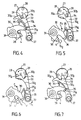
- the keeper 4 is a nipple which protrudes from the door jamb opposite the lock, the relative movement of the door in relation to the door jamb, in the direction of closing of the door, corresponding to a relative movement of the keeper 4 according to the arrow F1 of FIG. 6 and, in the direction of the door opening, relative movement of the striker 4 in the direction of arrow F2 in FIG. 5.
- the bolt 30 is capable of pivot around an axis 39 and it cooperates with a pawl 31, which is capable of pivoting around the axis 37.
- the pawl 31 is subjected to an elastic return force, which pushes it towards the bolt 30.
- the pawl 31 and the driver 32 are integral with each other in rotation about the axis 37: it follows that, when the rotation of the disc 27 continues, the pawl 31 pivots until allowing the exhaust of the notch 36 of the bolt 30 in which case the bolt is pivoted in the direction of the arrow F3, as shown in Figure 5. the spout 31a of the pawl 31 remains in abutment against an edge 35 of the bolt 30. This stage of operation is shown in Figure 5.
- FIGS 8 to 15 show a second embodiment of the lock according to the invention. It can be seen that said lock has been designated by 125 as a whole.
- the lock 125 includes an electric motor 109; on the motor shaft 109 is fixed a pinion 109 a , which meshes with a gear train 109 b , of which the output pinion 109 c meshes with a toothed wheel 127, which constitutes the rotary element controlling the operation of the lock.
- the rotary element 127 is a disc which carries two diametrically opposed crank pins 128, 129, said crank pins being formed on a cam 150, which is in relief on the disc 127.
- the cam 150 consists of two circular segments 150 a , symmetrical by relative to the center of the cam, the two circular segments being separated from each other by dimples 150 b , also symmetrical with respect to the center of the cam.
- An electrical switch 151 is interposed on the motor supply circuit 109; its control element 152 is a pusher, which cooperates with the edge of the cam 150: when the pusher rests on a circular segment 150 a , the switch is in a position which allows the motor 109 to be powered; on the contrary, when the control element 152 is in abutment against a recess 150 b , the switch is in a position which cuts the electrical supply to the motor 109 and which short-circuits the rotor of the motor for a given time .
- the lock according to this embodiment comprises a latch fork 130 capable of pivoting about an axis 139, said bolt cooperating with a keeper 104 of the same type as keeper 4 described for the first embodiment.
- the strike 104 can therefore, at the closing the door, move relative to the bolt 130 according to the arrow G1 of FIG. 8, to come and engage in the recess 138 of the bolt fork; when the keeper 104 comes into contact with one of the branches of the bolt fork 130, said bolt is driven in rotation about its axis 139 against a return means elastic.
- the pawl 131 of the lock is pushed by an elastic return against the bolt 130 and, during the pivoting of this bolt, the spout 131 a of the pawl engages in a notch 136 b formed in the edge of the bolt 130.
- This state of the kinematics is shown in Figure 9: the lock is closed at the first notch.
- crankpin 129 continues its travel, allows the spout 332 a to escape from the control lever 332, so that the coach 132 pivots about its axis 137 in the direction of the arrow G5 in FIG. 14 until return to the initial position shown in FIG. 8.
- the switch 151 had its control element 152 resting on a circular segment 150a of the cam 150, so that the motor 109 remained supplied with power .
- a recess 150b of the cam 150 comes in line with the control element 152, which cuts the electrical supply to the motor 109.
- the disc 127 continues to rotate at a small angle until the control element 152 is in the immediate vicinity of one end of the recess 150 b with which it cooperates.
- the driver 132 has pivoted according to the arrow G5
- the beak of the control lever 332 has pivoted about the axis 137, which allows the movement of the pawl 131 in the direction of the arrow G6 of FIG. 14 under the effect of its elastic return until the pawl 131 comes to bear against the elastic pawl stop 153.
Landscapes
- Lock And Its Accessories (AREA)
Description
- la figure 1 représente, schématiquement en plan, une vue d'ensemble d'un premier mode de réalisation de la serrure selon l'invention en position de fermeture ;
- les figures 2 à 7 représentent, schématiquement, pour la serrure de la figure 1, l'élément rotatif, l'entraíneur, le cliquet et le pêne de la serrure dans les différentes positions correspondant aux différentes phases cinématiques de l'ouverture et de la fermeture de ladite serrure ;
- la figure 8 représente, schématiquement dans son ensemble, une serrure selon une deuxième variante de l'invention, vue en plan en position d'ouverture ;
- les figures 9 à 14 représentent, schématiquement, l'élément rotatif, l'entraíneur, le cliquet et le pêne de la serrure dans les différentes positions correspondant aux différentes phases cinématiques de l'ouverture et de la fermeture de la serrure de la figure 8.
Claims (12)
- Serrure électrique pour un ouvrant de véhicule automobile comportant un pêne pivotant (30,130) en forme de fourche et un cliquet pivotant (31,131) soumis à un rappel élastique qui le pousse vers le pêne (30,130), ledit cliquet pouvant coopérer avec au moins un cran (36, 136a, 136b) du pêne (30,130) pour empêcher une rotation dudit pêne, le pêne (30,130) de ladite serrure coopérant avec une gâche (4,104) solidaire de la carrosserie, la fourche du pêne étant positionnée sur la trajectoire relative de la gâche (4,104) quand l'ouverture est amené en position de fermeture, de sorte que la gâche (4,104) fasse pivoter le pêne (30,130) jusqu'à une position de retenue dans laquelle le cliquet (31,131) empêche un pivotement inverse du pêne (30,130), ladite gâche étant alors prisonnière dans la fourche du pêne, le cliquet pouvant être manoeuvré par un moteur électrique (9, 109) à un seul sens de rotation qui entraíne un élément rotatif (27,127) portant deux manetons (28,29, 128,129) symétriques par rapport à son axe, l'un des manetons pouvant venir en contact avec un entraíneur (32,132) susceptible d'effectuer un mouvement de pivotement à l'encontre d'un rappel élastique, autour d'un axe fixe (37, 137) de l'entraíneur (32,132), qui lui-même, dans ce mouvement de pivotement effectué à l'encontre de son rappel élastique, fait pivoter le cliquet (31,131) à l'écart de sa position de retenue du pêne pour libérer le pêne en vue de l'ouverture de la serrure, l'élément rotatif (27,127) poursuivant sa rotation au moins jusqu'à ce que l'entraíneur (32,132) échappe à l'action du maneton et étant associé à un moyen d'arrêt du moteur, qui arrête sa rotation quand l'entraíneur (32,132) a échappé à l'action du maneton, caractérisée par le fait que chacun des deux manetons (28,29 ; 128,129) est apte à coopérer avec l'entraíneur (32,132) pour faire pivoter le cliquet (31,131) à l'écart de sa position de retenue du pêne, et par le fait que ledit entraíneur comporte, dans sa zone de coopération avec les manetons, un évidement (34) en forme de V dans lequel l'un ou l'autre maneton peut pénétrer pour générer le pivotement de l'entraíneur.
- Serrure selon la revendication 1, caractérisée par le fait que l'entraíneur (32) et le cliquet (31) sont solidaires l'un de l'autre.
- Serrure selon la revendication 1, caractérisée par le fait que l'entraíneur (132) est constitué de deux leviers solidaires en rotation, l'un constituant un levier d'ouverture (232) qui peut agir sur le cliquet pour provoquer son pivotement alors que l'autre constitue un levier de commande (332) qui porte l'évidement (134) coopérant avec l'un ou l'autre maneton (128, 129).
- Serrure selon la revendication 2, caractérisée par le fait que l'entraíneur (32) est un levier, ayant, vu en plan, la forme d'une botte, l'évidement (34) correspondant au creux, qui existe entre la partie semelle (32a) et la partie talon (32b) de la botte, l'articulation de pivotement dudit levier s'effectuant à son extrémité opposée à celle qui porte les parties (32a, 32b) de la botte.
- Serrure selon les revendications 1 et 4 prises en combinaison, caractérisée par le fait que le moyen d'arrêt du moteur est constitué, en premier lieu, par la mise en butée mécanique, contre la partie semelle (32a) de l'entraíneur (32), de celui des manetons (28, 29) qui n'a pas, pendant l'ouverture de serrure venant d'être réalisée, provoqué le pivotement de l'entraíneur (32) et, en deuxième lieu, par une coupure de l'alimentation du moteur, qui n'intervient qu'après la mise en butée mécanique du maneton contre l'entraíneur (32).
- Serrure selon l'une des revendications 4 ou 5, caractérisée par le fait que, dans la position d'ouverture de la serrure, le cliquet (31) s'appuie contre une bordure (35) du pêne (30) et que, lorsque la serrure axrive en position de fermeture, le cliquet (31) venant coopérer avec un cran (36) du pêne (30) sous l'action de son rappel élastique, l'entraíneur (32) et le cliquet (31) pivotent d'un angle suffisant pour que le maneton qui était au droit de la partie semelle (32a) de l'entraíneur se trouve au droit de l'évidement (34).
- Serrure selon la revendication 6, caractérisée par le fait que, dans la position de fermeture de la serrure, une bordure (32c) de l'entraíneur (32) vient en appui contre la bordure (35) du pêne (31).
- Serrure selon la revendication 5 prise seule ou en combinaison avec l'une des revendications 6 ou 7, caractérisée par le fait que la forme de la partie semelle (32a) de l'entraíneur (32) et de son raccordement à la zone, où se trouve l'axe de pivotement (37) dudit entraíneur, confère à ladite partie semelle (32a) une élasticité générant un léger rebond du maneton qui vient en appui sur ladite partie (32a), la partie talon (32b) de l'entraíneur se trouvant, au moment dudit appui, au droit de l'autre maneton pour limiter le rebond.
- Serrure selon l'une des revendications 4 à 7, caractérisée par le fait que la coupure de l'alimentation du moteur (9, 109) est dûe à une temporisation.
- Serrure selon la revendication 3, caractérisée par le fait que l'élément rotatif (127), qui porte les manetons, comporte une came (150), qui coopère avec l'élément de commande (152) d'un interrupteur (151), ledit interrupteur constituant le moyen d'arrêt unique du moteur.
- Serrure selon les revendications 1 et 10 prises en combinaison, caractérisée par le fait que la bordure de la came (150) comporte deux embrèvements (150b) symétriques l'un de l'autre par rapport à l'axe de l'élément rotatif (127), l'élément de commande (152) n'étant pas, lorsqu'il est au droit d'un embrèvement (150b), dans une position pour laquelle le moteur est alimenté alors qu'il permet l'alimentation du moteur (109), quand il s'appuie sur la bordure de la came (150) dans la zone circulaire (150a) ménagée entre les deux embrèvements (150b).
- Serrure selon l'une des revendications 10 ou 11, caractérisée par le fait que le rappel élastique du cliquet (131) amène ledit cliquet, lorsque la serrure est en position de fermeture, en appui contre une butée de cliquet fixe (153).
Applications Claiming Priority (2)
| Application Number | Priority Date | Filing Date | Title |
|---|---|---|---|
| DE19619958A DE19619958C2 (de) | 1996-05-17 | 1996-05-17 | Schloß für eine Kraftfahrzeugtür |
| DE19619958 | 1996-05-17 |
Publications (3)
| Publication Number | Publication Date |
|---|---|
| EP0812972A2 EP0812972A2 (fr) | 1997-12-17 |
| EP0812972A3 EP0812972A3 (fr) | 1999-03-03 |
| EP0812972B1 true EP0812972B1 (fr) | 2003-04-09 |
Family
ID=7794601
Family Applications (2)
| Application Number | Title | Priority Date | Filing Date |
|---|---|---|---|
| EP97401070A Expired - Lifetime EP0807734B1 (fr) | 1996-05-17 | 1997-05-14 | Serrure pour une portière de véhicule automobile |
| EP97401069A Expired - Lifetime EP0812972B1 (fr) | 1996-05-17 | 1997-05-14 | Serrure électrique pour ouvrant de véhicule automobile |
Family Applications Before (1)
| Application Number | Title | Priority Date | Filing Date |
|---|---|---|---|
| EP97401070A Expired - Lifetime EP0807734B1 (fr) | 1996-05-17 | 1997-05-14 | Serrure pour une portière de véhicule automobile |
Country Status (4)
| Country | Link |
|---|---|
| EP (2) | EP0807734B1 (fr) |
| BR (2) | BR9704848A (fr) |
| DE (3) | DE19619958C2 (fr) |
| ES (2) | ES2157053T3 (fr) |
Families Citing this family (31)
| Publication number | Priority date | Publication date | Assignee | Title |
|---|---|---|---|---|
| FR2775016B1 (fr) | 1998-02-19 | 2000-04-14 | Valeo Systemes De Fermetures | Perfectionnement aux serrures electriques d'ouvrant de vehic ule automobile avec fonctionnement en deux phases |
| GB2339593A (en) * | 1998-07-15 | 2000-02-02 | Meritor Light Vehicle Sys Ltd | Vehicle door latch with disengageable power release |
| FR2782111B1 (fr) | 1998-08-05 | 2002-12-06 | Valeo Securite Habitacle | Serrure electrique perfectionnee pour ouvrant de vehicule automobile |
| FR2783551B1 (fr) * | 1998-09-21 | 2000-11-17 | Valeo Securite Habitacle | Serrure electrique perfectionnee pour portiere de vehicule automobile |
| FR2783552B1 (fr) * | 1998-09-21 | 2000-11-17 | Valeo Securite Habitacle | Serrure electrique a assistance a l'ouverture pour portiere de vehicule automobile |
| US6109672A (en) | 1998-10-09 | 2000-08-29 | Valeo Electrical Systems, Inc. | Combination window release and wiper system and method |
| FR2785637B1 (fr) | 1998-11-09 | 2000-12-29 | Valeo Securite Habitacle | Serrure de porte de vehicule automobile a condamnation/decondamnation electrique |
| FR2794164B1 (fr) * | 1999-05-31 | 2001-07-27 | Valeo Securite Habitacle | Groupe moto-reducteur electrique et serrure comportant un tel groupe moto-reducteur |
| US6174016B1 (en) | 1999-10-15 | 2001-01-16 | Valeo Electrical Systems, Inc. | Door assembly module and method |
| FR2804713A1 (fr) | 2000-02-08 | 2001-08-10 | Valeo Securite Habitacle | Serrure electrique a contacteur de serrure ouverte et systeme d'une gache mobile et d'une telle serrure |
| DE10100008B4 (de) * | 2001-01-02 | 2004-12-16 | Brose Schließsysteme GmbH & Co.KG | Kraftfahrzeug-Türschloß, ausgeführt als Elektroschloß |
| DE10164829B4 (de) | 2001-01-02 | 2006-07-13 | Brose Schließsysteme GmbH & Co.KG | Kraftfahrzeug-Türschloss, ausgeführt als Elektroschloss |
| FR2821109B1 (fr) * | 2001-02-22 | 2003-04-11 | Valeo Securite Habitacle | Serrure electrique a actionnement de secours |
| DE10336049A1 (de) * | 2003-08-01 | 2005-02-17 | Kiekert Ag | Kraftfahrzeugtürverschluss |
| DE10361168B4 (de) * | 2003-12-22 | 2016-08-04 | BROSE SCHLIEßSYSTEME GMBH & CO. KG | Kraftfahrzeugschloß, insbesondere für Hauben oder Klappen |
| DE102005002493A1 (de) * | 2005-01-19 | 2006-07-27 | Marquardt Gmbh | Elektrisches Türschloß |
| JP4851869B2 (ja) * | 2006-07-03 | 2012-01-11 | 三井金属アクト株式会社 | 車両用ドアラッチ装置 |
| FR2929635B1 (fr) * | 2008-04-08 | 2010-06-11 | Valeo Securite Habitacle | Serrure de porte de vehicule automobile |
| ES2351747B1 (es) | 2008-09-16 | 2011-12-05 | Tubsa Automocion, S.L. | Cerradura motorizada de pestillo giratorio. |
| EP2431558A3 (fr) * | 2010-09-21 | 2016-06-01 | Gebr. Bode GmbH & Co. KG | Système de verrouillage et de déverrouillage |
| DE202012002867U1 (de) * | 2012-03-20 | 2012-04-11 | Flexngate Automotive Iberica S.A. | Schloss mit Drehriegel |
| US9546503B2 (en) * | 2013-03-06 | 2017-01-17 | Questek Manufacturing Corporation | Electromechanical rotary latch |
| DE102013103245A1 (de) * | 2013-03-28 | 2014-10-02 | Kiekert Aktiengesellschaft | Kraftfahrzeugtürverschluss |
| EP2843168B1 (fr) | 2013-09-02 | 2018-11-28 | Witte Automotive GmbH | Serrure de véhicule automobile |
| TWI617730B (zh) * | 2017-04-20 | 2018-03-11 | 信昌機械廠股份有限公司 | 上掀式車門的門鎖裝置(一) |
| CN109708398B (zh) * | 2018-07-26 | 2020-11-27 | 海尔智家股份有限公司 | 离合自动开门装置及冰箱 |
| CN110595141B (zh) * | 2018-07-26 | 2020-12-25 | 海尔智家股份有限公司 | 离合自动开门装置及冰箱 |
| CN109708396B (zh) * | 2018-07-26 | 2020-11-27 | 海尔智家股份有限公司 | 离合自动开门装置及冰箱 |
| CN109708399B (zh) * | 2018-07-26 | 2020-12-25 | 海尔智家股份有限公司 | 离合自动开门装置及冰箱 |
| DE102019116917A1 (de) * | 2019-06-24 | 2020-12-24 | Kiekert Aktiengesellschaft | Kraftfahrzeugschloss |
| DE102020118721A1 (de) * | 2020-07-15 | 2022-01-20 | Kiekert Aktiengesellschaft | Kraftfahrzeugschloss |
Family Cites Families (16)
| Publication number | Priority date | Publication date | Assignee | Title |
|---|---|---|---|---|
| DE3242527C3 (de) * | 1982-11-18 | 1995-09-07 | Neiman Sa | Schloß für eine Kraftfahrzeugtür |
| FR2539174B1 (fr) * | 1983-01-06 | 1987-05-22 | Peugeot Aciers Et Outillage | Serrure, notamment pour portiere de vehicule |
| DE3333746A1 (de) * | 1983-09-19 | 1985-06-05 | Neiman GmbH, 5657 Haan | Schloss fuer eine kraftfahrzeugtuer |
| US4904006A (en) * | 1986-10-06 | 1990-02-27 | Aisin Seiki Kabushiki Kaisha | Door lock assembly for automotive vehicles |
| US4763936A (en) * | 1986-10-20 | 1988-08-16 | General Motors Corporation | Power operated door latch |
| DE3728086A1 (de) * | 1987-08-22 | 1989-03-02 | Vdo Schindling | Schliesshilfe fuer eine fahrzeugtuer |
| JP2717098B2 (ja) * | 1988-07-21 | 1998-02-18 | アイシン精機株式会社 | ドアロツク装置 |
| JPH076313B2 (ja) * | 1988-08-25 | 1995-01-30 | 三井金属鉱業株式会社 | 自動車用アクチユエータ |
| JP2707637B2 (ja) * | 1988-09-30 | 1998-02-04 | アイシン精機株式会社 | ラゲージドアロック装置 |
| JPH0296072A (ja) * | 1988-09-30 | 1990-04-06 | Aisin Seiki Co Ltd | リッドロック装置 |
| DE4015522A1 (de) * | 1989-09-14 | 1991-03-28 | Bosch Gmbh Robert | Vorrichtung zum sperren und entsperren von geschlossenen tueren zum innenraum eines kraftfahrzeuges |
| JP2556792B2 (ja) * | 1991-12-13 | 1996-11-20 | 株式会社大井製作所 | 自動車用ドアロックの防盗アクチュエータ |
| DE4222868A1 (de) * | 1992-07-11 | 1994-01-13 | Bosch Gmbh Robert | Sperrvorrichtung für Türen eines Kraftfahrzeugs |
| DE4343340C2 (de) * | 1993-01-15 | 1996-04-04 | Kiekert Ag | Zentralgesteuerte Verschlußeinrichtung für Kraftfahrzeugtüren |
| JP2832236B2 (ja) * | 1993-09-03 | 1998-12-09 | 三井金属鉱業株式会社 | ドアロック装置用アクチュエータ |
| US5634677A (en) * | 1994-09-01 | 1997-06-03 | Kiekert Aktiengesellschaft | Power-locking motor-vehicle door latch |
-
1996
- 1996-05-17 DE DE19619958A patent/DE19619958C2/de not_active Expired - Lifetime
-
1997
- 1997-05-14 ES ES97401070T patent/ES2157053T3/es not_active Expired - Lifetime
- 1997-05-14 DE DE69720597T patent/DE69720597T2/de not_active Expired - Lifetime
- 1997-05-14 EP EP97401070A patent/EP0807734B1/fr not_active Expired - Lifetime
- 1997-05-14 ES ES97401069T patent/ES2196273T3/es not_active Expired - Lifetime
- 1997-05-14 DE DE69704587T patent/DE69704587T2/de not_active Expired - Lifetime
- 1997-05-14 EP EP97401069A patent/EP0812972B1/fr not_active Expired - Lifetime
- 1997-05-19 BR BR9704848-8A patent/BR9704848A/pt not_active IP Right Cessation
- 1997-05-19 BR BR9706869-1A patent/BR9706869A/pt not_active IP Right Cessation
Also Published As
| Publication number | Publication date |
|---|---|
| ES2196273T3 (es) | 2003-12-16 |
| DE69720597D1 (de) | 2003-05-15 |
| BR9706869A (pt) | 2003-05-27 |
| DE69704587T2 (de) | 2001-10-18 |
| EP0807734B1 (fr) | 2001-04-18 |
| EP0812972A3 (fr) | 1999-03-03 |
| DE19619958A1 (de) | 1997-11-20 |
| EP0807734A3 (fr) | 1999-01-20 |
| ES2157053T3 (es) | 2001-08-01 |
| BR9704848A (pt) | 2000-08-01 |
| DE69720597T2 (de) | 2003-12-24 |
| DE69704587D1 (de) | 2001-05-23 |
| EP0807734A2 (fr) | 1997-11-19 |
| DE19619958C2 (de) | 1999-10-21 |
| EP0812972A2 (fr) | 1997-12-17 |
Similar Documents
| Publication | Publication Date | Title |
|---|---|---|
| EP0812972B1 (fr) | Serrure électrique pour ouvrant de véhicule automobile | |
| EP0274287B1 (fr) | Serrure, notamment pour porte de véhicule automobile | |
| EP0215702B1 (fr) | Serrure à ouverture et fermeture électriques, notamment pour portières de véhicules automobiles | |
| EP0978610B1 (fr) | Serrure électrique perfectionnée pour ouvrant de véhicule automobile | |
| EP0989264B1 (fr) | Serrure électrique perfectionnée pour portière de vehicule automobile | |
| EP0119133A1 (fr) | Serrure à ouverture électrique, notamment pour portières de véhicules automobiles | |
| FR2704895A1 (fr) | Fermeture de porte pour véhicules automobiles avec système auxiliaire de fermeture et d'ouverture motorisé. | |
| EP0190976B1 (fr) | Mécanisme d'assistance à la fermeture d'une porte d'un véhicule automobile | |
| FR2518621A1 (fr) | Serrure pour porte de vehicule automobile | |
| EP0159238B1 (fr) | Dispositif électromécanique de commande de l'ouverture d'une serrure et serrure de portière de véhicule automobile comportant un tel dispositif | |
| FR3110623A1 (fr) | Dispositif d’accès de secours d’ouvrant de véhicule à bras de déploiement rotatif | |
| EP2115247B1 (fr) | Serrure électrique perfectionnée pour ouvrant de véhicule automobile | |
| EP0989265B1 (fr) | Serrure simplifiée pour portière de vèhicule automobile | |
| EP0989266B1 (fr) | Serrure à décondamnation automatique à l'ouverture | |
| EP1234937B1 (fr) | Serrure électrique à actionnement de secours | |
| EP0102263B1 (fr) | Serrure à commande électrique pour portière de véhicule automobile | |
| EP2640915B1 (fr) | Poignée de véhicule automobile ayant une masse inertielle de blocage actionnée par un contrepoids | |
| FR2804713A1 (fr) | Serrure electrique a contacteur de serrure ouverte et systeme d'une gache mobile et d'une telle serrure | |
| FR2638887A1 (fr) | Dispositif d'actionnement pour un interrupteur electrique, notamment associe a une porte ou un capot de vehicule automobile | |
| EP1724422B1 (fr) | Mécanisme de commande de l'ouverture d'une portière de véhicule automobile | |
| EP0989263B1 (fr) | Serrure électrique à assitance à l'ouverture pour portière de véhicule automobile | |
| EP0327460A1 (fr) | Interrupteur électrique à coupure automatique, en particulier interrupteur différentiel | |
| FR2769035A1 (fr) | Serrure de porte de vehicule comportant un dispositif de rearmement du levier d'ouverture exterieure | |
| FR2634246A1 (fr) | Dispositif de verrouillage d'un boitier avec couvercle formant par exemple vide-poches pour vehicule automobile | |
| FR2548253A1 (fr) | Dispositif a loquet pour serrure, notamment pour serrure de vehicule automobile |
Legal Events
| Date | Code | Title | Description |
|---|---|---|---|
| PUAI | Public reference made under article 153(3) epc to a published international application that has entered the european phase |
Free format text: ORIGINAL CODE: 0009012 |
|
| AK | Designated contracting states |
Kind code of ref document: A2 Designated state(s): DE ES FR GB IT |
|
| PUAL | Search report despatched |
Free format text: ORIGINAL CODE: 0009013 |
|
| AK | Designated contracting states |
Kind code of ref document: A3 Designated state(s): DE ES FR GB IT |
|
| 17P | Request for examination filed |
Effective date: 19990408 |
|
| 17Q | First examination report despatched |
Effective date: 20010427 |
|
| RAP1 | Party data changed (applicant data changed or rights of an application transferred) |
Owner name: VALEO SICHERHEITSSYSTEME GMBH Owner name: VALEO SECURITE HABITACLE |
|
| RAP1 | Party data changed (applicant data changed or rights of an application transferred) |
Owner name: VALEO SICHERHEITSSYSTEME GMBH Owner name: VALEO SECURITE HABITACLE |
|
| GRAG | Despatch of communication of intention to grant |
Free format text: ORIGINAL CODE: EPIDOS AGRA |
|
| GRAG | Despatch of communication of intention to grant |
Free format text: ORIGINAL CODE: EPIDOS AGRA |
|
| GRAH | Despatch of communication of intention to grant a patent |
Free format text: ORIGINAL CODE: EPIDOS IGRA |
|
| GRAH | Despatch of communication of intention to grant a patent |
Free format text: ORIGINAL CODE: EPIDOS IGRA |
|
| GRAA | (expected) grant |
Free format text: ORIGINAL CODE: 0009210 |
|
| AK | Designated contracting states |
Designated state(s): DE ES FR GB IT |
|
| REG | Reference to a national code |
Ref country code: GB Ref legal event code: FG4D Free format text: NOT ENGLISH |
|
| GBT | Gb: translation of ep patent filed (gb section 77(6)(a)/1977) |
Effective date: 20030409 |
|
| REG | Reference to a national code |
Ref country code: ES Ref legal event code: FG2A Ref document number: 2196273 Country of ref document: ES Kind code of ref document: T3 |
|
| PLBE | No opposition filed within time limit |
Free format text: ORIGINAL CODE: 0009261 |
|
| STAA | Information on the status of an ep patent application or granted ep patent |
Free format text: STATUS: NO OPPOSITION FILED WITHIN TIME LIMIT |
|
| 26N | No opposition filed |
Effective date: 20040112 |
|
| PGFP | Annual fee paid to national office [announced via postgrant information from national office to epo] |
Ref country code: GB Payment date: 20150518 Year of fee payment: 19 Ref country code: ES Payment date: 20150525 Year of fee payment: 19 |
|
| PGFP | Annual fee paid to national office [announced via postgrant information from national office to epo] |
Ref country code: IT Payment date: 20150512 Year of fee payment: 19 |
|
| REG | Reference to a national code |
Ref country code: ES Ref legal event code: PC2A Owner name: U-SHIN FRANCE SAS Effective date: 20160428 |
|
| REG | Reference to a national code |
Ref country code: FR Ref legal event code: PLFP Year of fee payment: 20 |
|
| PGFP | Annual fee paid to national office [announced via postgrant information from national office to epo] |
Ref country code: DE Payment date: 20160516 Year of fee payment: 20 |
|
| PGFP | Annual fee paid to national office [announced via postgrant information from national office to epo] |
Ref country code: FR Payment date: 20160527 Year of fee payment: 20 |
|
| GBPC | Gb: european patent ceased through non-payment of renewal fee |
Effective date: 20160514 |
|
| PG25 | Lapsed in a contracting state [announced via postgrant information from national office to epo] |
Ref country code: IT Free format text: LAPSE BECAUSE OF NON-PAYMENT OF DUE FEES Effective date: 20160514 |
|
| REG | Reference to a national code |
Ref country code: DE Ref legal event code: R071 Ref document number: 69720597 Country of ref document: DE |
|
| PG25 | Lapsed in a contracting state [announced via postgrant information from national office to epo] |
Ref country code: GB Free format text: LAPSE BECAUSE OF NON-PAYMENT OF DUE FEES Effective date: 20160514 |
|
| REG | Reference to a national code |
Ref country code: ES Ref legal event code: FD2A Effective date: 20180507 |
|
| PG25 | Lapsed in a contracting state [announced via postgrant information from national office to epo] |
Ref country code: ES Free format text: LAPSE BECAUSE OF NON-PAYMENT OF DUE FEES Effective date: 20160515 |