EP0811320B1 - Moulinet de pêche - Google Patents
Moulinet de pêche Download PDFInfo
- Publication number
- EP0811320B1 EP0811320B1 EP97303834A EP97303834A EP0811320B1 EP 0811320 B1 EP0811320 B1 EP 0811320B1 EP 97303834 A EP97303834 A EP 97303834A EP 97303834 A EP97303834 A EP 97303834A EP 0811320 B1 EP0811320 B1 EP 0811320B1
- Authority
- EP
- European Patent Office
- Prior art keywords
- rotor
- reel
- handle
- reel body
- engagement
- Prior art date
- Legal status (The legal status is an assumption and is not a legal conclusion. Google has not performed a legal analysis and makes no representation as to the accuracy of the status listed.)
- Expired - Lifetime
Links
Images


Classifications
-
- A—HUMAN NECESSITIES
- A01—AGRICULTURE; FORESTRY; ANIMAL HUSBANDRY; HUNTING; TRAPPING; FISHING
- A01K—ANIMAL HUSBANDRY; CARE OF BIRDS, FISHES, INSECTS; FISHING; REARING OR BREEDING ANIMALS, NOT OTHERWISE PROVIDED FOR; NEW BREEDS OF ANIMALS
- A01K89/00—Reels
- A01K89/01—Reels with pick-up, i.e. with the guiding member rotating and the spool not rotating during normal retrieval of the line
- A01K89/0117—Anti-reverse mechanisms
-
- A—HUMAN NECESSITIES
- A01—AGRICULTURE; FORESTRY; ANIMAL HUSBANDRY; HUNTING; TRAPPING; FISHING
- A01K—ANIMAL HUSBANDRY; CARE OF BIRDS, FISHES, INSECTS; FISHING; REARING OR BREEDING ANIMALS, NOT OTHERWISE PROVIDED FOR; NEW BREEDS OF ANIMALS
- A01K89/00—Reels
- A01K89/015—Reels with a rotary drum, i.e. with a rotating spool
-
- A—HUMAN NECESSITIES
- A01—AGRICULTURE; FORESTRY; ANIMAL HUSBANDRY; HUNTING; TRAPPING; FISHING
- A01K—ANIMAL HUSBANDRY; CARE OF BIRDS, FISHES, INSECTS; FISHING; REARING OR BREEDING ANIMALS, NOT OTHERWISE PROVIDED FOR; NEW BREEDS OF ANIMALS
- A01K89/00—Reels
- A01K89/01—Reels with pick-up, i.e. with the guiding member rotating and the spool not rotating during normal retrieval of the line
- A01K89/01121—Frame details
-
- A—HUMAN NECESSITIES
- A01—AGRICULTURE; FORESTRY; ANIMAL HUSBANDRY; HUNTING; TRAPPING; FISHING
- A01K—ANIMAL HUSBANDRY; CARE OF BIRDS, FISHES, INSECTS; FISHING; REARING OR BREEDING ANIMALS, NOT OTHERWISE PROVIDED FOR; NEW BREEDS OF ANIMALS
- A01K89/00—Reels
- A01K89/01—Reels with pick-up, i.e. with the guiding member rotating and the spool not rotating during normal retrieval of the line
- A01K89/0114—Reciprocating mechanisms
-
- A—HUMAN NECESSITIES
- A01—AGRICULTURE; FORESTRY; ANIMAL HUSBANDRY; HUNTING; TRAPPING; FISHING
- A01K—ANIMAL HUSBANDRY; CARE OF BIRDS, FISHES, INSECTS; FISHING; REARING OR BREEDING ANIMALS, NOT OTHERWISE PROVIDED FOR; NEW BREEDS OF ANIMALS
- A01K89/00—Reels
- A01K89/02—Brake devices for reels
- A01K89/027—Brake devices for reels with pick-up, i.e. for reels with the guiding member rotating and the spool not rotating during normal retrieval of the line
-
- A—HUMAN NECESSITIES
- A01—AGRICULTURE; FORESTRY; ANIMAL HUSBANDRY; HUNTING; TRAPPING; FISHING
- A01K—ANIMAL HUSBANDRY; CARE OF BIRDS, FISHES, INSECTS; FISHING; REARING OR BREEDING ANIMALS, NOT OTHERWISE PROVIDED FOR; NEW BREEDS OF ANIMALS
- A01K89/00—Reels
- A01K89/015—Reels with a rotary drum, i.e. with a rotating spool
- A01K89/0183—Drive mechanism details
Definitions
- the present invention relates to a spinning reel, and more particularly to a rotor drag type of spinning reel that is attached to a fishing rod and that allows the rotor to be braked during play-out of the line.
- a spinning reel is usually drag-operated by braking the spool while allowing it to rotate in the line play-out direction.
- line links accumulate as the line is repeatedly reeled in and played out, and this has led to the development of rotor drag type of spinning reel with which the drag operation is performed by reversing the rotor in the line play-out direction.
- a rotor drag type of spinning reel generally has a reel unit that has a handle; a pinion gear that is rotatably supported by the reel unit and that is rotated by a handle; a rotor that is rotatably supported by the reel unit and that is rotated by the pinion gear; a spool that includes a spool shaft that is supported by the reel unit such that it can move in the longitudinal direction; a level winding mechanism that moves the spool shaft in the longitudinal direction together with the pinion gear; and a braking mechanism that brakes the rotor when the rotor is reversed (Japanese Utility Model Publications 3-67574 and 3-56370, for instance).
- the rotor is balanced so that it will rotate smoothly.
- the braking mechanism has a brake plate that is engaged and rotated only when the rotor is reversed, and a brake lever that is pivotally supported by the reel unit and that presses the brake plate against the reel unit to effect braking.
- the bail With a rotor drag spinning reel having a braking mechanism such as this, the bail is swung into a line release attitude during line play-out.
- the handle When the fishing line is reeled in, the handle is operated to turn the rotor forward in the line winding direction and wind the fishing line on the spool. Meanwhile, when the fishing line is played out from the spool while the fisherman is fighting a fish, the brake plate is pressed against the reel unit by the brake lever, which brakes the rotor as it reverses, and performs a drag operation.
- US-A-4416427 discloses a rotor drag spinning reel in which engagement means are provided between the pinion gear and the rotor for engaging and disengaging the pinion gear and the rotor. This allows the pinion gear, and thus the handle, to be rotatable in only the line winding direction.
- the present invention provides an improvement over this prior art by providing a compact and less complex mechanism to effect both engagement/disengagement and braking.
- the bail of the reel is put into a line release attitude during line play-out.
- the fishing line is to be reeled in
- the handle is rotated in the line winding direction in a state in which the engagement means has been engaged by the operating means, then the rotation thereof will be transmitted to the rotor via the pinion gear and the engagement means, and the rotor will rotate in the line winding direction.
- the pinion gear will not be able to reverse with respect to the reel body, so the rotor will be braked according to the engagement force of the engagement means. Since the pinion gear does not reverse at this time, neither does the handle.
- the spool is moved in the longitudinal direction by the level winding means, and the fishing line is uniformly wound on the spool.
- the operating lever is movably positioned on the reel unit adjacent (in close proximity to) the mounting leg member, and is moved so as to adjust the frictional force by an operation in which the fishing rod, to which the spinning reel is attached, is grasped.
- the frictional force braking force
- the braking force can be adjusted with the hand gripping the fishing rod while the handle is operated with the other hand, which allows the braking force to be adjusted easily and at the right timing.
- the linking means links the reel body to the mounting leg member so that the reel body can pivot around the rotational axis of the handle. Since the handle shaft doubles as a pivot shaft, the structure of the mechanism is simpler.
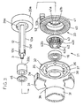
- the reel unit 2 has a reel body 2a, at the upper portion of which is formed a mounting leg member 2b for attaching the spinning reel to a fishing rod.
- the upper surface of the mounting leg member 2b is an rod mounting member 2c that comes into contact with the fishing rod.
- the interior of the reel body 2a is provided with a power transmission mechanism 5 that rotates the rotor 3 together with the rotation of the handle 1, and moves the spool 4 in the longitudinal direction.
- the spool 4 is positioned between the first rotor arm 3b and the second rotor arm 3c of the rotor 3, and is fixed at the tip of a spool shaft 8 that extends in the longitudinal direction.
- the spool 4 has a spooling drum 4a around the outside of which is wound the fishing line; a skirt 4b that is integrally formed at the rear of the spooling drum 4a; and a flange 4c that is fixed to the front end of the spooling drum 4a.
- the spool shaft 8 can be moved in the longitudinal direction by a level winding mechanism 7.
- the power transmission mechanism 5 includes a rotor drive braking mechanism 6 that is used to rotate and brake the rotor 3, and a level winding mechanism 7 that is used to uniformly wind the fishing line onto the spool 4 by moving the spool 4 in the longitudinal direction along the rotational axis X (i.e., the longitudinal axis).
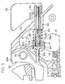
- a roller-type one-way clutch 20 is installed between the pinion gear 12 and the reel body 2a in front of the bearing 18, and the pinion gear 12 is only able to rotate in the line winding direction due to the one-way clutch 20.
- the one-way clutch 20 has an outer wheel 20a that is fixed to the reel body 2a, with sawtooth-like bumps 20d formed on the inside of this outer wheel 20a.
- An inner wheel 20b is non-rotatably mounted to the pinion gear 12.
- a transmission roller 20c is positioned between the outer wheel 20a and the inner wheel 20b.
- the clutch mechanism 13 has an engagement component 21 and an engagement holding component 22 that holds the engagement component 21 in an engaged state.
- the engagement component 21 has a receiving member 31 that is fixed to the rear end of the reel body 2a.
- Receiving plate 32 is movably and rotatably mounted on the rotor 3 to the rear of and facing the receiving member 31.
- Clutch plate 33 is non-rotatably but movably mounted on the pinion gear 12 to the rear of and facing the receiving plate 32.
- the receiving member 31 is a disk-shaped member that is screwed to the distal end of the front flange 2d of the reel body 2a.
- Metal balls 35 which are held in placed by a holder (not shown), are equidistantly arranged in the peripheral direction between this receiving member 31 and the receiving plate 32.
- the receiving member 31, receiving plate 32, and metal balls 35 make up a thrust bearing.
- the receiving plate 32 has a disk component 37 that has defined therein a circular hole 36 into which are fitted a pair of upper and lower tabs 3h formed at the rear end of the boss 3e of the rotor 3. Cylinder component 38 is fitted into the boss 3e.
- the clutch plate 33 has a metal clutch disk 40 that is positioned on the receiving plate 32 side, and a disk-shaped disk attachment component 41 to which the clutch disk 40 is fixed.
- Cylindrical linking member 42 supports the disk attachment component 41 such that it cannot rotate, but can move in the axial direction.
- a through hole 41b having inner splines 41a is formed in the center of the disk attachment component 41.
- An oval through hole 42a that engages with the chamfered surfaces 12d is formed in the center of the linking member 42, and outer splines 42b that mesh with the inner splines 41a are formed on the outer peripheral surface of the linking member 42.
- the linking member 42 is non-rotatably linked to the pinion gear 12.
- a notch 42c is formed in the peripheral direction around the outer peripheral surface. In this notch 42c is stopped the smaller-diameter end of a conical coil spring 43 that urges the clutch plate 33 rearward. The larger-diameter end of the conical coil spring 43 is stopped at the front surface of the disk attachment component 41.
- a washer 45 is positioned between the linking member 42 and the inner wheel of the one-way clutch 20.
- the operating mechanism 14 has an operating lever 50.
- the operating lever 50 is pivotally supported by a support shaft 51 on the reel body 2a in the boundary area between the reel body 2a and the mounting leg member 2b, and is urged in the direction of arrow A (counterclockwise) by an urging member (not shown).
- the operating lever 50 has a lever component 50a that curves out from the support shaft 51 and extends diagonally upward, and an engagement/disengagement actuator 50b provided to the distal end that curves out from the support shaft 51 and extends diagonally forward.
- Metal balls 52 are rotatably fitted into the engagement/disengagement actuator 50b. This engagement/disengagement actuator 50b presses the rear face of the clutch plate 33, moves the clutch plate 33 forward, and presses it against the receiving plate 32.
- the engagement holding component 22 switches the operating lever 50 between a released position (shown in Figure 4) and an engaged position (shown in Figure 5), and holds the operating lever 50 in an engaged state.
- the engagement holding component 22 has a shaft 60 that is rotatably supported around an axis parallel to the spool shaft 8 at the rear of the reel body 2a.
- Movable shaft 61 is supported at the distal end of the shaft 60 such that it cannot rotate, but can move in the axial direction.
- Adjustment spring 62 is positioned between the shaft 60 and the movable shaft 61 and urges the movable shaft 61 forward.
- a lever 63 is non-rotatably attached to the rear end of the shaft 60, and the shaft 60 is rotated 90 degrees by the lever 63 between 45 degrees to the left (the position in Figure 4) and 45 degrees to the right (the position in Figure 5).
- An adjustment screw 64 is screwed into the axial center of the shaft 60. The distal end of the adjustment screw 64 contacts an adjustment pin 65 that is mounted over the diameter line of the shaft 60 such that it can move in the axial direction. The ends of the adjustment pin 65 extend outward from the shaft 60, and are in contact with the rear end of the adjustment spring 62.
- the spring strength of the adjustment spring 62 (the force at which the movable shaft 61 is urged) can be adjusted by moving the adjustment pin 65 back and forth in the axial direction by means of the adjustment screw 64. Adjusting this urging force allows the braking force in an engaged state to be adjusted as desired. Also, outer splines 60a that are used for engagement with the movable shaft 61 are formed at the distal end of the shaft 60.
- the movable shaft 61 has on its distal end a striking component 61a that strikes a striking surface 50c formed on the operating lever 50.
- the striking component 61a is movably supported by the reel body 2a.
- the movable shaft 61 also has a large diameter component 61b that is contiguous with the striking component 61a.
- Inner splines 61c that mesh with the outer splines 60a of the shaft 60 are formed in the center of the large diameter component 61b.
- a cylindrical cam lobe 61d that protrudes radially is provided to the outer peripheral surface of the large diameter component 61b. This cam lobe 61d is positioned such that it moves along an inclined cam 66 formed in the reel body 2a.
- This cam lobe 61d moves along the inclined cam 66 as a result of the urging force of the adjustment spring 62 and the rotation of the shaft 60, and this causes the movable shaft 61 to advance or retract in the axial direction, which rotates the operating lever 50.
- the level winding mechanism 7 is used to uniformly wind the fishing line on the spool 4 by moving the spool shaft 8 in the longitudinal direction and thereby causing the spool 4 to move back and forth in the same direction.
- the level winding mechanism 7 has a spiral shaft 71 that is positioned beneath the spool shaft 8.
- a slider 72 moves in the longitudinal direction along the spiral shaft 71; the rear end of the spool shaft 8 is fixed to slider 72.
- a first intermediate gear 73 is fixed to the distal end of the spiral shaft 71.
- Two intersecting spiral grooves 71a are formed on the outer peripheral surface of the spiral shaft 71.
- the slider 72 has an engagement member (not shown) that engages with the spiral grooves 71a, and is guided parallel to the spool shaft 8 by a guide mechanism (not shown).
- the first intermediate gear 73 meshes with a second intermediate gear 74 positioned under it.
- the second intermediate gear 74 is fixed to the rear end of an intermediate shaft 75 that is rotatably supported by the front flange 2d of the reel body 2a.
- a third intermediate gear 76 that meshes with the inside teeth 3g of the rotor 3 is fixed to the distal end of the intermediate shaft 75.
- the bail arm 9 is lowered to a line release attitude, and the fishing rod is swung in a casting motion.
- the fishing line wound around the outside of the spool 4 is played out by the weight of the tackle.
- the bail arm 9 When the fishing line is to be reeled in, the bail arm 9 is returned to a line winding attitude. Also, the lever 63 is rotated from 45 degrees left to 45 degrees right to put the engagement component 21 in an engaged state. Specifically, when the lever 63 is thus rotated, the shaft 60 pivots, and the movable shaft 61 engaged with the splines also pivots. When the movable shaft 61 pivots, the cam lobe 61d provided to the outer peripheral surface of the large diameter component 61b thereof moves forward along the inclined cam 66, the movable shaft 61 advances, the distal end of the striking component 61a strikes the striking surface 50c of the operating lever 50, and the operating lever 50 is rotated to its engagement position.
- the engagement/disengagement actuator 50b presses against the rear surface of the clutch plate 33 and causes the clutch plate 33 to move forward and press against the receiving plate 32. As a result, the engagement component 21 is held in an engaged state.
- the lever 63 When the rotor 3 is reversed during a fight with a fish, the lever 63 is rotated to 45 degrees left to put the engagement component 21 in a released state. When the lever 63 is rotated from 45 degrees right to 45 degrees left, the cam lobe 61d retracts along the inclined cam 66, and the movable shaft 61 retracts. The operating lever 50 is then returned to its release position by an urging member (not shown). The operating lever 50 is operated in this state while a fish is on the line. When the fishing line is pulled by the fish and the rotor 3 is reversed, the force is transmitted to the receiving plate 32, and the receiving plate 32 rotates integrally with the rotor 3.
- a protrusion 2e that protrudes downward is formed at the lower end of the reel body 2a.
- a rectangular through hole 2f (which goes through in the longitudinal direction) is formed in the interior of this protrusion 2e, and the engagement component 90 is provided to this through hole 2f.
- the engagement component 90 has a nut 91 that is threaded onto the threads 85.
- the nut 91 has a shaft 92 that protrudes outward on both sides.
- This shaft 92 is rotatably supported by a bearing 93.
- This bearing 93 is supported such that it can move up and down by a guide component 94 formed in the through hole 2f.
- the adjustment shaft 83 is rotated by the turning of the knob 84, which results in the nut 91 that is threaded onto the threads 85 moving in the longitudinal direction.
- the reel body 2a pivots around the handle shaft 10.
- the receiving plate 132 and clutch plate 133 may consist of cup-shaped members, and a radial bearing may be made up of a ring-shaped receiving member 131, the receiving plate 32, and the metal balls 35.
- the clutch plate 33 is lowered by pivoting, which presses the clutch plate 33 against the receiving plate 32.
Landscapes
- Life Sciences & Earth Sciences (AREA)
- Environmental Sciences (AREA)
- Animal Husbandry (AREA)
- Biodiversity & Conservation Biology (AREA)
Claims (12)
- Un moulinet à tambour avec traínée rotor comprenant :caractérisé en ce que ledit moyen d'engrènement (13, 21) transmet de l'énergie à l'aide d'une force de frottement, et en ce que ledit moyen d'actionnement (14) comprend un levier d'actionnement (50) actionnant ledit moyen d'engrènement pour exécuter lesdits engrènement et désengrènement.(i) un bloc de moulinet (2) comprenant(a) un corps de moulinet (2a),(b) un élément constituant patte de montage (2b), et(c) une poignée (1);(ii) un rotor (3) qui est soutenu de façon à pouvoir tourner par ledit corps de moulinet ;(iii) un tambour (4) ; et(iv) un mécanisme de transmission d'énergie (5) destiné à faire tourner ledit rotor (3) en conjonction avec la rotation de ladite poignée (1), ledit mécanisme (5) comprenant(a) une roue d'engrenage (12) qui est soutenue par ledit corps de moulinet (2a), peut être tournée uniquement dans le sens d'enroulement de ligne et qui tourne en conjonction avec ladite poignée (1),(b) un moyen d'engrènement (13, 21) prévu entre ladite roue d'engrenage (12) et ledit rotor (3) destiné à s'engrener avec ladite roue d'engrenage (12) et ledit rotor (3) et à se désengrener de ceux-ci, et(c) un moyen d'actionnement (14) pouvant être déplacé par rapport audit bloc de moulinet (2) pour régler une force de frottement d'engrènement ;
- Un moulinet à tambour tel que défini dans la revendication 1, dans lequel ledit mécanisme de transmission d'énergie (5) comprend de plus un moyen de maintien en engrènement (22) destiné à maintenir ledit moyen d'engrènement (13, 21) dans un état engrené.
- Un moulinet à tambour tel que défini dans la revendication 1 ou la revendication 2, dans lequel ledit levier d'actionnement (50) est positionné de façon à pouvoir se déplacer sur ledit bloc de moulinet (2) adjacent audit élément constituant patte de montage (2b) et est adapté pour être déplacé de façon à régler ladite force de frottement par une opération consistant à saisir une canne à pêche à laquelle est attaché ledit moulinet à tambour.
- Un moulinet à tambour tel que défini dans n'importe quelle revendication précédente, dans lequel ledit moyen d'engrènement (13, 21) comprend(a) un élément de réception (31) fixé à l'extrémité avant dudit corps de moulinet (2a) ;(b) une plaque de réception (32) montée de façon à pouvoir se déplacer et tourner sur ledit rotor (3) à l'arrière dudit élément de réception (31) et face à celui-ci ; et(c) un plateau d'embrayage (33) monté de façon à ne pas pouvoir tourner mais à pouvoir se déplacer sur ladite roue d'engrenage (12) à l'arrière de ladite plaque de réception (32) et face à celle-ci.
- Un moulinet à tambour tel que défini dans la revendication 4, dans lequel ledit moyen d'actionnement (14) comprend de plus un organe de commande d'engrènement (50b) qui répond au déplacement dudit levier d'actionnement (50) pour déplacer ledit plateau d'embrayage (33) contre la plaque de réception (32).
- Un moulinet à tambour tel que défini dans l'une ou l'autre des revendications 4 et 5, dans lequel(a) l'élément de réception (31) est configuré en anneau ;(b) la plaque de réception (32) est configurée en cuvette ; et(c) le plateau d'embrayage (33) est configuré en cuvette.
- Un moulinet à tambour tel que défini dans n'importe quelle revendication précédente, dans lequel ledit moyen d'actionnement (14) a un élément rotatif (60) qui, lorsqu'il est tourné, se déplace dans le sens longitudinal dudit bloc de moulinet (2) et règle ladite force de frottement.
- Un moulinet à tambour tel que défini dans n'importe quelle revendication précédente, dans lequel ledit rotor (3) est soutenu de façon à pouvoir tourner par un élément cylindrique (12a) qui tourne de façon solidaire avec ladite roue d'engrenage.
- Un moulinet à tambour tel que défini dans n'importe quelle revendication précédente, comprenant de plus un moyen de liaison destiné à relier ledit corps de moulinet (2a) audit élément constituant patte de montage (2b) grâce à quoi ledit corps de moulinet (2a) peut pivoter autour d'un axe parallèle à un axe de rotation de ladite poignée (1) et un moyen de réglage (81) destiné à régler la position dudit corps de moulinet (2a).
- Un moulinet à tambour tel que défini dans la revendication 9, dans lequel ledit moyen de liaison relie ledit corps de moulinet (2a) audit élément constituant patte de montage (2b) de sorte que ledit corps de moulinet puisse pivoter autour dudit axe de rotation de ladite poignée.
- Un moulinet à tambour avec traínée rotor tel que défini dans n'importe quelle revendication précédente, dans lequel :l'élément constituant patte de montage (2b) s'étend à partir du corps de moulinet (2a) et comporte un élément de montage de canne (2c) ;la poignée (1) est soutenue de façon à pouvoir tourner par le corps de moulinet (2a) ;le tambour (4) est disposé sur le corps de moulinet (2a) devant le rotor (3) de telle sorte que le tambour (4) puisse se déplacer dans le sens longitudinal ;le mécanisme de transmission d'énergie (5) est adapté en outre pour déplacer ledit tambour (4) dans le sens longitudinal et comporte un moyen d'enroulement régulier (7) répondant à la rotation de la poignée (1).
- Un moulinet à tambour tel que défini dans la revendication 11, dans lequel ledit moyen d'enroulement régulier (7) tourne en conjonction avec ledit rotor (3) et déplace ledit tambour (4) dans le sens longitudinal.
Applications Claiming Priority (3)
| Application Number | Priority Date | Filing Date | Title |
|---|---|---|---|
| JP141474/96 | 1996-06-04 | ||
| JP14147496 | 1996-06-04 | ||
| JP14147496A JP3585318B2 (ja) | 1996-06-04 | 1996-06-04 | スピニングリール |
Publications (3)
| Publication Number | Publication Date |
|---|---|
| EP0811320A2 EP0811320A2 (fr) | 1997-12-10 |
| EP0811320A3 EP0811320A3 (fr) | 1998-08-26 |
| EP0811320B1 true EP0811320B1 (fr) | 2002-10-30 |
Family
ID=15292736
Family Applications (1)
| Application Number | Title | Priority Date | Filing Date |
|---|---|---|---|
| EP97303834A Expired - Lifetime EP0811320B1 (fr) | 1996-06-04 | 1997-06-04 | Moulinet de pêche |
Country Status (9)
| Country | Link |
|---|---|
| US (1) | US5863007A (fr) |
| EP (1) | EP0811320B1 (fr) |
| JP (1) | JP3585318B2 (fr) |
| KR (1) | KR100471570B1 (fr) |
| CN (1) | CN1096829C (fr) |
| DE (1) | DE69716669T2 (fr) |
| DK (1) | DK0811320T3 (fr) |
| MY (1) | MY126360A (fr) |
| TW (1) | TW334335B (fr) |
Cited By (1)
| Publication number | Priority date | Publication date | Assignee | Title |
|---|---|---|---|---|
| EP3491920A1 (fr) * | 2017-11-29 | 2019-06-05 | Globeride, Inc. | Dispositif anti-retour pour bobine de fil de pêche et bobine de fil de pêche associé |
Families Citing this family (14)
| Publication number | Priority date | Publication date | Assignee | Title |
|---|---|---|---|---|
| JP3854732B2 (ja) * | 1998-09-17 | 2006-12-06 | 株式会社シマノ | スピニングリールのマスターギア |
| JP4785305B2 (ja) * | 2001-09-17 | 2011-10-05 | 株式会社シマノ | スピニングリール |
| JP3977672B2 (ja) * | 2002-03-15 | 2007-09-19 | 株式会社シマノ | スピニングリールのロータ制動装置 |
| US6860442B2 (en) * | 2003-07-19 | 2005-03-01 | Penn Fishing Tackle Manufacturing Co. | Locking preset knob for fishing reel |
| IT1399344B1 (it) * | 2010-04-08 | 2013-04-16 | Rovella | " mulinello da pesca per canne da lancio con dispositivo di freno a comando a leva ". |
| US8469300B2 (en) | 2011-07-22 | 2013-06-25 | Eastaboga Tacle Mfg. Co., Inc. | Spinning reel |
| JP6046385B2 (ja) * | 2012-06-18 | 2016-12-14 | 株式会社シマノ | 電動リールのレベルワインド機構 |
| JP6261884B2 (ja) * | 2013-06-05 | 2018-01-17 | 株式会社シマノ | 魚釣用スピニングリール及びそのロータ制動装置の制動操作レバー |
| JP6247843B2 (ja) * | 2013-06-21 | 2017-12-13 | 株式会社シマノ | 魚釣用スピニングリール及びそのロータ制動装置の制動操作レバー |
| JP6636748B2 (ja) * | 2015-08-20 | 2020-01-29 | 株式会社シマノ | スピニングリール |
| JP6846332B2 (ja) * | 2017-11-29 | 2021-03-24 | グローブライド株式会社 | 魚釣用スピニングリールの逆転防止装置 |
| US10869467B1 (en) * | 2017-12-13 | 2020-12-22 | Thomas Sandstrom | Spinning type fishing reel with bi-directionally rotating rotor and drag control to prevent line twist |
| JP2018161139A (ja) * | 2018-06-15 | 2018-10-18 | 株式会社シマノ | スピニングリール |
| JP6856738B2 (ja) * | 2019-12-19 | 2021-04-07 | 株式会社シマノ | スピニングリール |
Family Cites Families (14)
| Publication number | Priority date | Publication date | Assignee | Title |
|---|---|---|---|---|
| US2711292A (en) * | 1952-10-17 | 1955-06-21 | John K Taggart | Spinning type of fishing reel |
| US2918227A (en) * | 1952-11-03 | 1959-12-22 | Mauborgne Paul | Variable drive device for fishing winches |
| US3948465A (en) * | 1974-05-30 | 1976-04-06 | Scusa Paul A | Fishing reel construction |
| JPS6010381Y2 (ja) * | 1980-05-30 | 1985-04-09 | ダイワ精工株式会社 | 魚釣用スピニングリ−ルのドラグ調整装置 |
| JPS6011795Y2 (ja) * | 1980-05-30 | 1985-04-18 | ダイワ精工株式会社 | 魚釣用スピニングリ−ルのドラグ操作装置 |
| GB2112611B (en) * | 1981-11-05 | 1985-05-09 | Shakespeare Co | Fishing reel assembly |
| JPS58178876U (ja) * | 1982-05-26 | 1983-11-30 | 株式会社シマノ | スピニングリ−ル |
| JPH0328773Y2 (fr) * | 1985-06-10 | 1991-06-20 | ||
| JPH0697981B2 (ja) * | 1989-08-08 | 1994-12-07 | アーベストフーズ株式会社 | 果実の種子部分抜去装置および詰物型加工食品の製造装置並びにそれにより製造された詰物型加工食品 |
| JP2536456Y2 (ja) * | 1991-03-22 | 1997-05-21 | 株式会社シマノ | スピニングリールの逆転防止構造 |
| JP2528079Y2 (ja) * | 1992-01-30 | 1997-03-05 | ダイワ精工株式会社 | 魚釣用リール |
| JP3184590B2 (ja) * | 1992-02-14 | 2001-07-09 | 株式会社シマノ | スピニングリール |
| JP3034756B2 (ja) * | 1993-10-18 | 2000-04-17 | ダイワ精工株式会社 | 魚釣用スピニングリール |
| JP3438949B2 (ja) * | 1994-06-27 | 2003-08-18 | 株式会社シマノ | スピニングリールの逆転防止装置 |
-
1996
- 1996-06-04 JP JP14147496A patent/JP3585318B2/ja not_active Expired - Fee Related
-
1997
- 1997-02-24 TW TW086102213A patent/TW334335B/zh active
- 1997-03-06 KR KR1019970007420A patent/KR100471570B1/ko not_active IP Right Cessation
- 1997-04-23 US US08/838,928 patent/US5863007A/en not_active Expired - Fee Related
- 1997-04-24 MY MYPI97001791A patent/MY126360A/en unknown
- 1997-06-04 CN CN97105489A patent/CN1096829C/zh not_active Expired - Fee Related
- 1997-06-04 DK DK97303834T patent/DK0811320T3/da active
- 1997-06-04 EP EP97303834A patent/EP0811320B1/fr not_active Expired - Lifetime
- 1997-06-04 DE DE69716669T patent/DE69716669T2/de not_active Expired - Fee Related
Cited By (4)
| Publication number | Priority date | Publication date | Assignee | Title |
|---|---|---|---|---|
| EP3491920A1 (fr) * | 2017-11-29 | 2019-06-05 | Globeride, Inc. | Dispositif anti-retour pour bobine de fil de pêche et bobine de fil de pêche associé |
| CN109997815A (zh) * | 2017-11-29 | 2019-07-12 | 古洛布莱株式会社 | 钓鱼用旋压式卷线器的反转防止装置以及旋压式卷线器 |
| US10506802B2 (en) | 2017-11-29 | 2019-12-17 | Globeride, Inc. | Anti-reverse device for fishing spinning reel and fishing spinning reel having the same |
| CN109997815B (zh) * | 2017-11-29 | 2021-08-17 | 古洛布莱株式会社 | 钓鱼用旋压式卷线器的反转防止装置以及旋压式卷线器 |
Also Published As
| Publication number | Publication date |
|---|---|
| EP0811320A3 (fr) | 1998-08-26 |
| EP0811320A2 (fr) | 1997-12-10 |
| DK0811320T3 (da) | 2003-03-03 |
| JP3585318B2 (ja) | 2004-11-04 |
| CN1096829C (zh) | 2002-12-25 |
| TW334335B (en) | 1998-06-21 |
| KR100471570B1 (ko) | 2005-08-09 |
| KR980000041A (ko) | 1998-03-30 |
| DE69716669D1 (de) | 2002-12-05 |
| MY126360A (en) | 2006-09-29 |
| JPH09322679A (ja) | 1997-12-16 |
| CN1171882A (zh) | 1998-02-04 |
| US5863007A (en) | 1999-01-26 |
| DE69716669T2 (de) | 2003-07-24 |
Similar Documents
| Publication | Publication Date | Title |
|---|---|---|
| EP0811320B1 (fr) | Moulinet de pêche | |
| US4142694A (en) | Bait casting fishing reel | |
| US5120001A (en) | Fishing reel with drag mechanism | |
| US5350132A (en) | Anti-reverse structure for a spinning reel | |
| KR100471572B1 (ko) | 스피닝릴의페이스기어 | |
| US5988549A (en) | Spinning reel with guard arm | |
| US3152771A (en) | Fishing reel | |
| JPH10304799A (ja) | 両軸受けリールの遠心制動装置 | |
| EP0711500A1 (fr) | Moulinet de pêche | |
| JP3981325B2 (ja) | スピニングリールのスプール支持構造 | |
| US3175781A (en) | Clutch for fishing reel | |
| US4756487A (en) | Spin cast reel with rear drag adjustment | |
| JP3569372B2 (ja) | 釣用リールの発音機構 | |
| US5358196A (en) | Drag mechanism for a spinning reel | |
| US5775613A (en) | Anti-reverse system for a fishing reel | |
| EP0701775B1 (fr) | Dispositif d'oscillation pour moulinet de pêche | |
| JP4002356B2 (ja) | スピニングリールのスプール | |
| JP3103070U (ja) | 両軸受けリール | |
| JPH0451586Y2 (fr) | ||
| JPH0220215B2 (fr) | ||
| JPH0216630Y2 (fr) | ||
| JPH0994047A (ja) | 両軸受リール | |
| JPH1052198A (ja) | バックラッシュ防止 ベイトリール | |
| JP2594929Y2 (ja) | スピニングリール | |
| JPH0142468Y2 (fr) |
Legal Events
| Date | Code | Title | Description |
|---|---|---|---|
| PUAI | Public reference made under article 153(3) epc to a published international application that has entered the european phase |
Free format text: ORIGINAL CODE: 0009012 |
|
| AK | Designated contracting states |
Kind code of ref document: A2 Designated state(s): BE DE DK FR GB IT LU NL SE |
|
| AX | Request for extension of the european patent |
Free format text: AL;LT;LV;SI |
|
| PUAL | Search report despatched |
Free format text: ORIGINAL CODE: 0009013 |
|
| AK | Designated contracting states |
Kind code of ref document: A3 Designated state(s): AT BE CH DE DK ES FI FR GB GR IE IT LI LU MC NL PT SE |
|
| AX | Request for extension of the european patent |
Free format text: AL;LT;LV;SI |
|
| AKX | Designation fees paid | ||
| RBV | Designated contracting states (corrected) | ||
| RBV | Designated contracting states (corrected) |
Designated state(s): BE DE DK FR GB IT LU NL SE |
|
| 17P | Request for examination filed |
Effective date: 19990413 |
|
| 17Q | First examination report despatched |
Effective date: 20010402 |
|
| GRAG | Despatch of communication of intention to grant |
Free format text: ORIGINAL CODE: EPIDOS AGRA |
|
| GRAG | Despatch of communication of intention to grant |
Free format text: ORIGINAL CODE: EPIDOS AGRA |
|
| GRAH | Despatch of communication of intention to grant a patent |
Free format text: ORIGINAL CODE: EPIDOS IGRA |
|
| GRAH | Despatch of communication of intention to grant a patent |
Free format text: ORIGINAL CODE: EPIDOS IGRA |
|
| GRAA | (expected) grant |
Free format text: ORIGINAL CODE: 0009210 |
|
| AK | Designated contracting states |
Kind code of ref document: B1 Designated state(s): BE DE DK FR GB IT LU NL SE |
|
| REG | Reference to a national code |
Ref country code: GB Ref legal event code: FG4D |
|
| REF | Corresponds to: |
Ref document number: 69716669 Country of ref document: DE Date of ref document: 20021205 |
|
| REG | Reference to a national code |
Ref country code: DK Ref legal event code: T3 |
|
| PGFP | Annual fee paid to national office [announced via postgrant information from national office to epo] |
Ref country code: SE Payment date: 20030604 Year of fee payment: 7 |
|
| PGFP | Annual fee paid to national office [announced via postgrant information from national office to epo] |
Ref country code: LU Payment date: 20030612 Year of fee payment: 7 |
|
| ET | Fr: translation filed | ||
| PGFP | Annual fee paid to national office [announced via postgrant information from national office to epo] |
Ref country code: DK Payment date: 20030613 Year of fee payment: 7 |
|
| PLBE | No opposition filed within time limit |
Free format text: ORIGINAL CODE: 0009261 |
|
| STAA | Information on the status of an ep patent application or granted ep patent |
Free format text: STATUS: NO OPPOSITION FILED WITHIN TIME LIMIT |
|
| 26N | No opposition filed |
Effective date: 20030731 |
|
| PGFP | Annual fee paid to national office [announced via postgrant information from national office to epo] |
Ref country code: NL Payment date: 20040603 Year of fee payment: 8 |
|
| PG25 | Lapsed in a contracting state [announced via postgrant information from national office to epo] |
Ref country code: LU Free format text: LAPSE BECAUSE OF NON-PAYMENT OF DUE FEES Effective date: 20040604 |
|
| PG25 | Lapsed in a contracting state [announced via postgrant information from national office to epo] |
Ref country code: SE Free format text: LAPSE BECAUSE OF NON-PAYMENT OF DUE FEES Effective date: 20040605 |
|
| PGFP | Annual fee paid to national office [announced via postgrant information from national office to epo] |
Ref country code: FR Payment date: 20040608 Year of fee payment: 8 |
|
| PG25 | Lapsed in a contracting state [announced via postgrant information from national office to epo] |
Ref country code: DK Free format text: LAPSE BECAUSE OF NON-PAYMENT OF DUE FEES Effective date: 20040630 |
|
| PGFP | Annual fee paid to national office [announced via postgrant information from national office to epo] |
Ref country code: BE Payment date: 20040813 Year of fee payment: 8 |
|
| REG | Reference to a national code |
Ref country code: DK Ref legal event code: EBP |
|
| EUG | Se: european patent has lapsed | ||
| EUG | Se: european patent has lapsed | ||
| PG25 | Lapsed in a contracting state [announced via postgrant information from national office to epo] |
Ref country code: BE Free format text: LAPSE BECAUSE OF NON-PAYMENT OF DUE FEES Effective date: 20050630 |
|
| PG25 | Lapsed in a contracting state [announced via postgrant information from national office to epo] |
Ref country code: NL Free format text: LAPSE BECAUSE OF NON-PAYMENT OF DUE FEES Effective date: 20060101 |
|
| PG25 | Lapsed in a contracting state [announced via postgrant information from national office to epo] |
Ref country code: FR Free format text: LAPSE BECAUSE OF NON-PAYMENT OF DUE FEES Effective date: 20060228 |
|
| NLV4 | Nl: lapsed or anulled due to non-payment of the annual fee |
Effective date: 20060101 |
|
| REG | Reference to a national code |
Ref country code: FR Ref legal event code: ST Effective date: 20060228 |
|
| PGFP | Annual fee paid to national office [announced via postgrant information from national office to epo] |
Ref country code: GB Payment date: 20060531 Year of fee payment: 10 |
|
| PGFP | Annual fee paid to national office [announced via postgrant information from national office to epo] |
Ref country code: DE Payment date: 20060601 Year of fee payment: 10 |
|
| PGFP | Annual fee paid to national office [announced via postgrant information from national office to epo] |
Ref country code: IT Payment date: 20060630 Year of fee payment: 10 |
|
| BERE | Be: lapsed |
Owner name: *SHIMANO INC. Effective date: 20050630 |
|
| GBPC | Gb: european patent ceased through non-payment of renewal fee |
Effective date: 20070604 |
|
| PG25 | Lapsed in a contracting state [announced via postgrant information from national office to epo] |
Ref country code: DE Free format text: LAPSE BECAUSE OF NON-PAYMENT OF DUE FEES Effective date: 20080101 |
|
| PG25 | Lapsed in a contracting state [announced via postgrant information from national office to epo] |
Ref country code: GB Free format text: LAPSE BECAUSE OF NON-PAYMENT OF DUE FEES Effective date: 20070604 |
|
| PG25 | Lapsed in a contracting state [announced via postgrant information from national office to epo] |
Ref country code: IT Free format text: LAPSE BECAUSE OF NON-PAYMENT OF DUE FEES Effective date: 20070604 |