EP0809962B1 - Poignée à manche - Google Patents
Poignée à manche Download PDFInfo
- Publication number
- EP0809962B1 EP0809962B1 EP97107065A EP97107065A EP0809962B1 EP 0809962 B1 EP0809962 B1 EP 0809962B1 EP 97107065 A EP97107065 A EP 97107065A EP 97107065 A EP97107065 A EP 97107065A EP 0809962 B1 EP0809962 B1 EP 0809962B1
- Authority
- EP
- European Patent Office
- Prior art keywords
- handle
- bearing bush
- shank
- base part
- type handle
- Prior art date
- Legal status (The legal status is an assumption and is not a legal conclusion. Google has not performed a legal analysis and makes no representation as to the accuracy of the status listed.)
- Expired - Lifetime
Links
- 239000000463 material Substances 0.000 claims description 7
- 229920001343 polytetrafluoroethylene Polymers 0.000 claims description 5
- 239000004810 polytetrafluoroethylene Substances 0.000 claims description 5
- 229920001187 thermosetting polymer Polymers 0.000 claims description 5
- 229920001169 thermoplastic Polymers 0.000 claims description 3
- 239000004416 thermosoftening plastic Substances 0.000 claims description 3
- 230000002093 peripheral effect Effects 0.000 claims description 2
- 238000010276 construction Methods 0.000 claims 1
- 238000010411 cooking Methods 0.000 claims 1
- 230000037431 insertion Effects 0.000 claims 1
- 238000003780 insertion Methods 0.000 claims 1
- 230000000284 resting effect Effects 0.000 claims 1
- 238000004806 packaging method and process Methods 0.000 abstract description 4
- 238000009835 boiling Methods 0.000 abstract 1
- 238000004519 manufacturing process Methods 0.000 description 8
- 239000012815 thermoplastic material Substances 0.000 description 4
- 230000015572 biosynthetic process Effects 0.000 description 3
- 230000000694 effects Effects 0.000 description 2
- 239000000725 suspension Substances 0.000 description 2
- 210000003813 thumb Anatomy 0.000 description 2
- -1 Polytetrafluoroethylene Polymers 0.000 description 1
- 239000006096 absorbing agent Substances 0.000 description 1
- 230000006978 adaptation Effects 0.000 description 1
- 239000003831 antifriction material Substances 0.000 description 1
- 230000001771 impaired effect Effects 0.000 description 1
- 230000000149 penetrating effect Effects 0.000 description 1
- 239000004033 plastic Substances 0.000 description 1
- 230000036316 preload Effects 0.000 description 1
- 238000004080 punching Methods 0.000 description 1
- 230000035939 shock Effects 0.000 description 1
- 238000010408 sweeping Methods 0.000 description 1
- XLYOFNOQVPJJNP-UHFFFAOYSA-N water Substances O XLYOFNOQVPJJNP-UHFFFAOYSA-N 0.000 description 1
Images


Classifications
-
- A—HUMAN NECESSITIES
- A47—FURNITURE; DOMESTIC ARTICLES OR APPLIANCES; COFFEE MILLS; SPICE MILLS; SUCTION CLEANERS IN GENERAL
- A47J—KITCHEN EQUIPMENT; COFFEE MILLS; SPICE MILLS; APPARATUS FOR MAKING BEVERAGES
- A47J45/00—Devices for fastening or gripping kitchen utensils or crockery
- A47J45/06—Handles for hollow-ware articles
- A47J45/061—Saucepan, frying-pan handles
Definitions
- the invention relates to a handle for a handle Dishes, especially roasting, baking or Cookware made using a Fastening element on the wall of a Harness is attachable, the handle of the handle or an essential part of the handle by one Vertical axis from a protruding from the dishes Use position in an approximately parallel or tangential directed to the wall of dishes or in a Mouth of the surface of the dishes overlapping Rest position is pivotable, the handle of a handle base part attachable to the harness and one on Base part of the handle which can be pivoted exists, the base part with a guide surface annular guide groove or annular Has a lead that is centric from the Pivotal axis is penetrated, and the Handle her with the base part connectable end area a suitable Leading surface with lead or Has guide groove, the one another gripping and contiguous Guide elements through a the swivel axis forming lanyard together are held.
- the invention is based on the object a handle of the generic type create a flawless Centering and guidance between the base part and swiveling handle is guaranteed, even if the interacting items Show manufacturing tolerances.
- the pivot axis of a bearing bush is formed with a flange on the outside of the Handle is supported, handle and that Reaches through the base part and through itself supporting outside of the base part
- Fasteners can be fixed that the Fasteners from an annular or cylindrical spring element and one this axially penetrating head bolt, there, the spring element a domed spring washer, the Midrange firmly against the bottom of the Bearing bush using the head pin is tightenable and the edge area itself under tension on the bottom of the Base part supports.
- the axial game in this Swivel is formed by training the Spring element, in particular in the form of a Belleville washer, eliminated, being a certain Shock absorber effect is achieved. Means the fastener becomes the connection brought to the desired preload, so that in spite of tolerant production of the Individual parts a tight fit is accessible and the flexibility is guaranteed.
- the Vertical axis parallel to the central axis of the Dishes directed or slightly opposite the central axis is inclined.
- Crockery items are regularly circular trained so that the central axis of this Circular shape practically the central axis of the Forms dishes.
- To the central axis of the Crockery is supposed to be the vertical axis that the Forms the pivot axis of the handle, parallel or slightly opposite be inclined to the central axis.
- Control unit a cylindrical push button is.
- the arrangement of the Control panel preferably on the top of the Handle training is made so that the Users of this control panel at hand gripped grip with the thumb of the hand can operate.
- the friction-reducing material is PTFE.
- the top and bottom in the area of Guide surfaces on the handle or on Base part are arranged despite appropriate pre-tensioning of the connection the parts a desired smooth Guaranteed rotatability of the handle.
- the arrangement preferably made so that the handle is in the rest position approximately tangential to the peripheral wall of the Parts of the crockery are also on the outside Adjustment of the handle in the way possible that the handle in the Use position almost radially from that corresponding crockery protrudes while in the rest position the handle on the inside is pivoted so that it almost over the Mouth of the dishes or, if it is is a cover part over which Cover surface is arranged so that only insignificant radial projections remain.
- the outside of the Remaining protrusions are not bigger than usual ones Bow handles or the like, so that especially with the arrangement in Packaging or the like this protruding areas in the corners of the Packaging must be arranged so that no additional space required within the Packaging exists.
- the base part and the Handle made of a thermoset and the Bearing bush made of thermoplastic, whereby the outer diameter of the bearing bush in the into the center hole of the handle of the Handle-reaching area smaller diameter than the center hole has, so that the parts with radial Interlock game.
- thermoset material for the base part and the handle becomes one thick-walled training enables one accordingly viable training of interlocking parts (annular groove and ring-shaped guide surfaces) allows while the bearing bush relative can be made thin-walled by for the production of thermoplastic material is used.
- the bearing bush takes over no or only insignificant Leadership roles because the real Guided tour through the ring alone Guide groove and the corresponding annular guide surfaces is reached whereby a turntable is formed, that remains functional in the long run, because through the use of thermoset as Manufacturing material one Tolerance change over longer Use times do not occur. All in all it is fixed by screwing it on the spring washer on the underside of the Base part, so that a fixed The connection has been pretensioned, however, a certain suspension is possible is. As a result of the sufficient game between the bearing bush and the Mounting area for the bearing bush in the Punching the handle becomes permanent Function guaranteed, even if that Thermoplastic material of the bearing bush over should swell for a longer period of use.
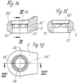
- the Locking grooves of the bearing bush radially surrounding area of the handle in pairs opposite each other are arranged, such a pair of Locking grooves in which the Locking pin in the swiveled-in position Rest position with play intervenes Axial grooves are formed that are parallel have extending groove flanks, while a second pair of locking grooves, in which the locking pin in the intervenes in the swung out position of use, is formed by axially directed grooves, the mutually converging groove flanks at least in the top of the handle have facing end area between which the locking pin free of play can be introduced.
- the one pair of locking grooves which parallel groove flanks has, serves for assembly and is also after successful assembly to accommodate the Locking pin in the pivoted Rest position used.
- a sufficient play between flanks and Locking pin desired to the to allow easy assembly being in the swiveled-in position also none backlash-free arrangement is achieved what is also not necessary.
- the handle is by means of a fastening element 2 the side wall of the dishes 1 attachable.
- the handle 3 or one essential part of the handle is over a vertical axis 4 from one of the dishes 1 transversely protruding position of use (cf. Figure 1 to 3) in an approximately parallel or directed tangentially to the wall of dishes Rest position pivotable, as in Figure 4 and 5 shown in solid lines, or also in a the mouth or area of the Tableware 1 comprehensive rest position pivotable, as in Figure 5 in dash-dotted lines are shown.
- the vertical axis 4 can be parallel to Center axis 5 of the dishes 1 directed be or slightly opposite the central axis be inclined, in particular from the Representation according to FIG. 6 can be seen.
- the handle 3 is preferably made of one on the wall of the dishes 1 attachable base part 6 and one on Base part 6 swiveling (about the axis 4) Handle 7.
- the base part 6 has guide surfaces 8, 9 with annular guide groove 10 on the centrally penetrated by the pivot axis 4 is while the handle 7 on her with the base part 6 connectable end region a matching guide surface 11 or 12 with guide projection 13.
- the target position is, for example, from FIG. 1 and Figure 4 can be seen interlocking and together adjacent guide elements by a Swivel axis or part of the Lanyard forming swivel axis held together.
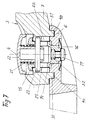
- the pivot axis 4 is preferably one Bearing bush 14 formed with a Flange 15 on the outside (top) the handle 7 supports. The arrangement is made so that the flange 15 practically flush in the bottom of the handle 7 lies.
- the bearing bush 14 extends through it Base part 6 and is by itself outside of the base part 6 supporting Fasteners can be fixed.
- the fastener consists of a annular spring element, preferably in Shape of an arched spring washer, and one that penetrates axially Head bolt 17, preferably one Cap screw in a thread formation 30 at the bottom of the bearing bush 14 can be screwed in. That as a domed Spring washer 16 is in the target assembly position with its stepped middle region 18 firmly against the Bottom 19 of the socket 14 by means of Fastener 17 tightened. Here the edge area of the Spring element 16 under tension on the Bottom of the base part at 20 onwards. On this way is in spite of tolerance Individual parts a firm fixation of the parts reached each other, with a certain Suspension of the handle 7 is guaranteed and yet not the rotatability is impaired.
- the handle 3, especially the handle 7 is in the two possible extreme positions lockable.
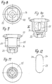
- the bearing bush 14 on her Flange 15 provided end of a spring element 21 and one under tension of the Spring element 21 axially to the bearing bush 14 slidably engaging in this Control panel 22 in the form of a cylindrical Push button provided.
- the latter is from a locking pin 23 penetrates the in a radial through bore 24 of the Control panel can be used.
- the Locking pin 23 passes through the Bearing bush 14 transverse to its longitudinal axis in directed parallel to its longitudinal axis Elongated holes 25, making the travel in Axis direction of axis 4 of the control panel 22 is limited.
- the locking pin 23 projects radially beyond the bearing bush 14.
- the adjacent guide surfaces 9, 11 of base part 6 and handle 7 are made particularly slippery by the fact that between these surfaces sliding washers 27 are made of PTFE.
- the spring element 21 is in the Embodiment as a coil spring trained, the coil spring itself on the one hand on a shoulder 28 of the Bearing bush 14 supports and on the other hand a corresponding support surface 29 of the Control element 22.
- the handle 3 is completed in the following way. It will be the first Washer 27 in the groove 10 of the base part 6 inserted, then the handle 7 with the appropriate fitting surfaces and the further sliding disc 27 is placed.
- the Upper slide plate 27 is between the flange 15 of the socket 14 and the Top of the handle 7. Before that is the Bushing 14 by using parts 21, 22 and 23 have been completed. These parts are in the right position 7 brought in. The final fixation is then done by hanging up the Spring element 16 and attaching the Fastening element 17 (screw in the threaded hole 30).
- a handle 3 shown for a tableware the by means of a fastener the wall of the dishes is attachable.
- the handle 3 is about a vertical axis 4 from a protruding from the dishes Use position in a parallel or directed tangentially to the wall of dishes or into the mouth or area of the Rest position across dishes swiveling.
- the handle 3 consists in essentially one on the dishes attachable base part 6 and one on Base part pivotally supported Handle 7.
- the base part 6 has a annular guide groove 10 on the centrally penetrated by the swivel axis is.
- the handle 7 points to her with the Base part 6 connectable end region matching guide surface with annular guide projection 31, the interlocking and adjacent guide elements through a forming the swivel axis Lanyards are held together.
- the pivot axis 4 is one Bearing bush 14 formed with a Flange 15 on the outside of the handle is supported. It reaches through the handle 7 and the base part 6 and is by a the outside of the base part 6 (below) supporting fastener fixable.
- This fastener consists of one annular or cylindrical Spring element 16 and this one axially sweeping fasteners in shape of a head bolt 17, which in one in the Bearing bush 14 held non-rotatably Nut 32 can be screwed in.
- the Spring element 16 is an arched Spring washer, the middle area of which is graduated is and firmly against the bottom of the Bearing bush 14 by means of the head bolt 17 is tightenable, while the edge area itself under spring tension on the bottom the base part 6 supports.
- the Bearing bush 14 is on its with flange 15 provided end of a spring element 21 and under the bias of the spring element 21 axially displaceable to the bearing bush Control panel 22 used by a Locking pin 23 is penetrated transversely.
- the locking pin 23 passes through the Bearing bush 14 transverse to its longitudinal axis in directed parallel to its longitudinal axis Elongated holes 25 and dominates the bearing bush 14 radial with both ends. With these Ends engages the locking pin 23 in axial locking grooves 26, 26 'through the Bearing bush 14 radially surrounding area the perforation of the handle 7.
- the base part 6 and the handle 7 made of a thermoset, while the bearing bush 14 and if necessary, the control unit 22 Thermoplastic exists.
- the Outer diameter of the bearing bush 14 in the in the center hole of the handle 7 of the Handle handle 3 area with smaller diameter than the center hole trained so that the parts with radial Interlock game.
- the thread formation 32 having The end of the bearing bush 14 is in cross section designed as a polygon.
- the polygon is designated 33.
- the elongated holes 25 of the bearing bush 14 are in the one near the mouth End area (in the drawing above) conical or narrowed in a wedge shape.
- the narrowing is designated 34. This allows the Locking pin first in the intervene extended area with game, before it then penetrates into the constriction 34 and is thus kept free of play.
- the axial grooves 26,26 'of the bearing bush 14 radially surrounding area of the handle 7 are opposed to each other in pairs arranged, such a pair of Locking grooves 26, in which the Locking pin 23 in the swung in rest position with play engages, is formed by axial grooves, the parallel groove flanks have and thus easy assembly and a playful seat of the Allow locking pin.
- the second pair of locking grooves 26 ' in which the locking pin 23 in the intervenes in the swung out position of use, is formed by axially directed grooves, the mutually converging groove flanks at least in the top of the handle have facing end region, such as can be seen in particular from FIG. The locking pin can be inserted into these grooves intervene first with game until he then got into the constriction area and there is kept free of play.
Landscapes
- Food Science & Technology (AREA)
- Engineering & Computer Science (AREA)
- Cookers (AREA)
- Details Of Rigid Or Semi-Rigid Containers (AREA)
- Purses, Travelling Bags, Baskets, Or Suitcases (AREA)
- Food-Manufacturing Devices (AREA)
- Washing And Drying Of Tableware (AREA)
- Pivots And Pivotal Connections (AREA)
- Frying-Pans Or Fryers (AREA)
- Materials For Medical Uses (AREA)
- Switch Cases, Indication, And Locking (AREA)
- Domestic Plumbing Installations (AREA)
- Steering Devices For Bicycles And Motorcycles (AREA)
Claims (11)
- Poignée à manche pour des ustensiles de cuisine, notamment des ustensiles de cuisson pour faire cuire, frire ou bouillir des aliments, qui peut être fixée au moyen d'un élément de fixation sur la paroi d'un ustensile de cuisine, la poignée à manche ou une majeure partie de la poignée à manche pouvant être pivotée, autour d'un axe vertical, d'une position d'utilisation faisant saillie de l'ustensile transversalement à ce dernier dans une position de repos orientée environ parallèlement ou tangentiellement à la paroi de l'ustensile, ou bien recouvrant l'ouverture ou la surface de l'ustensile, la poignée à manche étant constituée d'une partie de socle pouvant être fixée sur l'ustensile et d'un manche fixé à pivotement sur la partie de socle, la partie de socle présentant une face de guidage à rainure de guidage annulaire ou à saillie de guidage annulaire, qui est traversée centralement par l'axe de pivotement, et le manche présentant, sur sa région terminale pouvant être assemblée à la partie de socle, une face de guidage correspondante, à saillie de guidage ou à rainure de guidage, les éléments de guidage en engagement mutuel et application mutuelle étant maintenus assemblés par un moyen d'assemblage formant l'axe de pivotement, caractérisée en ce que l'axe de pivotement (4) est formé par un coussinet (14), qui s'appuie par un collet (15) contre le côté extérieur du manche (7), traverse le manche (7) et la partie de socle (6) et peut être fixé en position par un moyen de fixation s'appuyant extérieurement contre la partie de socle (6), et en ce que le moyen de fixation est constitué d'un élément élastique (16) annulaire ou cylindrique et d'un axe à épaulement (17) traversant axialement cet élément, l'élément élastique (16) étant une rondelle élastique bombée, dont la région centrale peut être bloquée contre le côté inférieur du coussinet (14) au moyen de l'axe à épaulement (17), et dont la région de bord s appuie sous précontrainte contre le côté inférieur de la partie de socle (6).
- Poignée à manche selon la revendication 1, caractérisée en ce que l'axe vertical (4) est orienté parallèlement à l'axe médian (5) de l'ustensile (1), ou est légèrement incliné par rapport à cet axe médian.
- Poignée à manche selon la revendication 1 ou 2, caractérisée en ce que la poignée à manche (3) peut être verrouillée dans les deux positions extrêmes possibles.
- Poignée à manche selon une des revendications 1 à 3, caracterisée en ce qu'un élément élastique (21) et un élément de manoeuvre (22), mobile axialement par rapport au coussinet sous la précontrainte de l'élément élastique (21), sont installés dans le coussinet (14) à son extrémité pourvue du collet (15), l'élément de manoeuvre (22) étant traversé transversalement par une goupille de verrouillage (23), la goupille de verrouillage (23) traversant le coussinet (14) transversalement à son axe longitudinal, dans des trous oblongs (25) orientés parallèlement à l'axe longitudinal, dépassant radialement du coussinet (14) et s'engageant dans des rainures axiales de verrouillage (26) de la région du manche (7) qui entoure radialement le coussinet (14), de sorte que, lorsque l'élément de manoeuvre (22) n'est pas sollicité, le manche (7) ne peut pas être déplacé par pivotement dans la position d'utilisation ou dans la position de repos et, lorsque l'élément de manoeuvre (22) est axialement sollicité et déplacé, les extrémités de la goupille de verrouillage (23) sont désengagées des rainures axiales de verrouillage (26), et le manche (7) peut être pivoté autour du coussinet (14).
- Poignée à manche selon la revendication 4, caractérisée en ce que l'élément de manoeuvre (22) est un bouton-poussoir cylindrique.
- Poignée à manche selon une des revendications 1 à 5, caractérisée en ce que les faces de guidage en application mutuelle de la partie de socle (6) et du manche (7), ainsi que du collet (15) et du manche (7), sont recouvertes d'un matériau réduisant le frottement, ou bien des rondelles de glissement (27) en un tel matériau sont disposées entre les faces.
- Poignée à manche selon la revendication 6, caractérisée en ce que le matériau réduisant le frottement est du polytétrafluoréthylène.
- Poignée à manche selon une des revendications 1 à 7, caractérisée en ce que la partie de socle (6) et le manche (7) sont réalisés en matériau thermodurcissable et le coussinet (14) en matériau thermoplastique, le diamètre extérieur du coussinet (14) étant, dans la région traversant le perçage central du manche (7) de la poignée à manche, inférieur au diamètre de ce perçage, de sorte que les pièces s'engagent l'une dans l'autre avec jeu radial.
- Poignée à manche selon la revendication 8, caractérisée en ce que l'extrémité du coussinet (14) qui présente le filetage (32) est réalisée de section polygonale, et la région d'insertion dans le perçage de la partie de socle (6) est de forme identique.
- Poignée à manche selon la revendication 8 ou 9, caractérisée en ce que les trous oblongs (25) du coussinet (14) sont, au moins dans leur région terminale proche de l'embouchure, rétrécis coniquement ou en forme de coin, et la goupille de verrouillage (23) s'engage sans jeu dans le rétrécissement.
- Poignée à manche selon les revendications 8 à 10, caractérisée en ce que les rainures de verrouillage (26, 26') de la région du manche (7) qui entoure radialement le coussinet (14) sont disposées en vis-à-vis par paires, une première paire de rainures de verrouillage (26), dans laquelle la goupille de verrouillage (23) s'engage avec jeu dans la position de repos pivotée vers l'intérieur, étant formée par des rainures axiales qui présentent des flancs de rainures s'étendant en parallèle, tandis qu'une seconde paire de rainures de verrouillage (26'), dans laquelle la goupille de verrouillage (23) s'engage dans la position d'utilisation pivotée vers l'extérieur, est formée par des rainures orientées axialement qui présentent des flancs de rainure convergeant l'un vers l'autre au moins dans la région terminale tournée vers le côté supérieur de la poignée, flancs entre lesquels la goupille de verrouillage (23) peut être introduite sans jeu.
Applications Claiming Priority (4)
| Application Number | Priority Date | Filing Date | Title |
|---|---|---|---|
| DE19621524A DE19621524C1 (de) | 1996-05-29 | 1996-05-29 | Stielgriff |
| DE19621524 | 1996-05-29 | ||
| DE19653228 | 1996-12-20 | ||
| DE19653228A DE19653228A1 (de) | 1996-05-29 | 1996-12-20 | Stielgriff |
Publications (2)
| Publication Number | Publication Date |
|---|---|
| EP0809962A1 EP0809962A1 (fr) | 1997-12-03 |
| EP0809962B1 true EP0809962B1 (fr) | 1999-09-29 |
Family
ID=26026122
Family Applications (1)
| Application Number | Title | Priority Date | Filing Date |
|---|---|---|---|
| EP97107065A Expired - Lifetime EP0809962B1 (fr) | 1996-05-29 | 1997-04-29 | Poignée à manche |
Country Status (10)
| Country | Link |
|---|---|
| US (1) | US6173860B1 (fr) |
| EP (1) | EP0809962B1 (fr) |
| JP (1) | JPH10216026A (fr) |
| KR (1) | KR100289875B1 (fr) |
| AT (1) | ATE185053T1 (fr) |
| AU (1) | AU706490B2 (fr) |
| BR (1) | BR9709276A (fr) |
| DE (2) | DE19653228A1 (fr) |
| TR (1) | TR199802470T2 (fr) |
| WO (1) | WO1997045046A1 (fr) |
Cited By (1)
| Publication number | Priority date | Publication date | Assignee | Title |
|---|---|---|---|---|
| FR2898030A1 (fr) * | 2006-03-06 | 2007-09-07 | Seb Sa | Dispositif de prehension pour ustensile culinaire |
Families Citing this family (39)
| Publication number | Priority date | Publication date | Assignee | Title |
|---|---|---|---|---|
| ITTO980274A1 (it) * | 1998-03-27 | 1999-09-27 | Termoplastic Fbm Srl | Dispositivo di impugnatura per un recipiente di cottura per cibi, in particolare per una padella |
| US6257439B1 (en) * | 1999-12-01 | 2001-07-10 | Te Hui Hsu | Handle for a food container |
| US6439420B1 (en) * | 2001-03-29 | 2002-08-27 | Jong Peter Park | Detachable handle for cooking utensil |
| FR2883153B1 (fr) * | 2005-03-17 | 2007-04-20 | Seb Sa | Dispositif de prehension pivotant pour un ustensile culinaire |
| ITMI20052289A1 (it) * | 2005-11-30 | 2007-06-01 | Ballarini Paolo & Figli Spa | Maniglia oscillabile per un contenitore da cucina |
| ITMI20060233A1 (it) * | 2006-02-10 | 2007-08-11 | Ballarini Paolo & Figli Spa | Manico reclinabile per una padella |
| ES1062429Y (es) * | 2006-03-10 | 2006-09-16 | Rayen Sl | Sarten |
| CN100546530C (zh) * | 2006-05-09 | 2009-10-07 | 陆意祥 | 一种锅用手柄 |
| GB2444476A (en) * | 2006-12-06 | 2008-06-11 | Otter Controls Ltd | Crepe maker |
| US7975874B2 (en) * | 2008-08-11 | 2011-07-12 | Ian Scott | Bracket and handle for cooking vessel |
| KR100923419B1 (ko) * | 2008-12-29 | 2009-10-23 | (주)드림셰프 | 주방용기용 손잡이 |
| GB2473027B (en) * | 2009-08-27 | 2011-08-03 | Spearmark Internat Ltd | A drink receptacle |
| US8276242B2 (en) * | 2010-04-09 | 2012-10-02 | Girard Mylene | Adjustable handle assembly with locking mechanism |
| FR2958519B1 (fr) * | 2010-04-13 | 2013-09-13 | Seb Sa | Poignee pivotante pour recipient de cuisson comportant un verrou retractable dans le moyeu |
| FR2958520B1 (fr) * | 2010-04-13 | 2013-09-13 | Seb Sa | Poignee pivotante pour recipient de cuisson comportant au moins deux clenches de verrouillage |
| ITBS20100139A1 (it) * | 2010-08-09 | 2012-02-10 | Bialetti Ind Spa | Supporto per moka per piano da cucina ad induzione |
| CN102068213B (zh) * | 2010-12-07 | 2012-09-05 | 浙江苏泊尔股份有限公司 | 一种可旋转炊具手柄 |
| US9060640B2 (en) * | 2011-12-16 | 2015-06-23 | National Presto Industries, Inc. | Countertop appliance having detachable base |
| US8950621B2 (en) * | 2012-03-02 | 2015-02-10 | Charles HINZMAN | Cooking utensil with rotatable handle |
| ITMI20122066A1 (it) * | 2012-12-03 | 2014-06-04 | Sanmiro S R L | Manico rotabile di utensile da cucina. |
| ITMI20122067A1 (it) * | 2012-12-03 | 2014-06-04 | Sanmiro S R L | Manico rotabile di utensile da cucina. |
| WO2014165706A1 (fr) * | 2013-04-04 | 2014-10-09 | Meyer Intellectual Properties Ltd. | Poignée détachable et récipient de batterie de cuisine |
| CN103690059B (zh) * | 2014-01-15 | 2016-08-17 | 浙江苏泊尔家电制造有限公司 | 煎烤机 |
| CN103690060B (zh) * | 2014-01-15 | 2017-01-18 | 浙江苏泊尔家电制造有限公司 | 煎烤机 |
| KR101509482B1 (ko) * | 2014-05-29 | 2015-04-08 | 이동우 | 주방용기용 접이식 손잡이 구조 |
| US20150366384A1 (en) * | 2014-06-23 | 2015-12-24 | Jeff Cates | Beverage containers |
| KR200476325Y1 (ko) | 2014-07-21 | 2015-02-16 | 주식회사 로이첸 | 프라이팬 |
| USD751334S1 (en) * | 2014-08-04 | 2016-03-15 | X.J. Electrics (Hubei) Co., Ltd | Pan |
| CN204015936U (zh) * | 2014-08-04 | 2014-12-17 | 湖北香江电器股份有限公司 | 折叠式平底锅 |
| US10238228B2 (en) * | 2016-02-16 | 2019-03-26 | Meyer Intellectual Properties Limited | Composite cookware handle |
| EP3484333A4 (fr) * | 2016-07-13 | 2019-11-27 | Sea To Summit Pty Ltd | Poignée destinée à un récipient, à un outil à main ou à un autre article similaire |
| US20230322444A1 (en) * | 2022-04-06 | 2023-10-12 | Newbury Holdings, LLC | Drinking vessel with rotating handle |
| USD1047582S1 (en) | 2023-04-14 | 2024-10-22 | Sea To Summit Pty Ltd | Cookware handle mount |
| USD1047581S1 (en) | 2023-04-14 | 2024-10-22 | Sea To Summit Pty Ltd | Cookware handle |
| USD1047584S1 (en) | 2023-04-14 | 2024-10-22 | Sea To Summit Pty Ltd | Cookware handle |
| USD1083488S1 (en) * | 2023-06-26 | 2025-07-15 | Joseph Joseph, Ltd. | Cookware handle |
| CN222264946U (zh) * | 2023-12-15 | 2024-12-31 | 摇斯菲尔产品有限公司 | 一种具有可转动把手的水杯 |
| USD1083489S1 (en) * | 2023-12-22 | 2025-07-15 | Joseph Joseph, Ltd. | Cookware handle |
| EP4606285A1 (fr) * | 2024-02-22 | 2025-08-27 | La Termoplastic F.B.M. - S.r.l. | Poignée pour un récipient de cuisson |
Family Cites Families (8)
| Publication number | Priority date | Publication date | Assignee | Title |
|---|---|---|---|---|
| US66173A (en) * | 1867-06-25 | Improved handle attachment foe blacking-boxes | ||
| US1490568A (en) * | 1922-05-26 | 1924-04-15 | Koenig Remus | Combination frying pan and cooker |
| US2361417A (en) * | 1943-11-15 | 1944-10-31 | James H Reichart | Endless, self-clamping handled band |
| US3777094A (en) * | 1971-09-09 | 1973-12-04 | Environment One Corp | Thermally insulated cookware for dynamic induction field heating and cooking apparatus |
| US3838680A (en) * | 1973-07-16 | 1974-10-01 | P Shipman | Combination heating and serving assembly |
| DE8029340U1 (de) * | 1980-11-04 | 1981-03-12 | Schroff Gmbh, 7541 Straubenhardt | Gelenkverbindung |
| US4645905A (en) * | 1985-02-27 | 1987-02-24 | Dart Industries, Inc. | Foldable household appliance |
| JPH0425097Y2 (fr) * | 1986-05-27 | 1992-06-15 |
-
1996
- 1996-12-20 DE DE19653228A patent/DE19653228A1/de not_active Withdrawn
-
1997
- 1997-04-26 BR BR9709276-2A patent/BR9709276A/pt not_active Application Discontinuation
- 1997-04-26 AU AU29495/97A patent/AU706490B2/en not_active Ceased
- 1997-04-26 WO PCT/DE1997/000878 patent/WO1997045046A1/fr not_active Ceased
- 1997-04-26 TR TR1998/02470T patent/TR199802470T2/xx unknown
- 1997-04-26 US US09/180,220 patent/US6173860B1/en not_active Expired - Fee Related
- 1997-04-29 DE DE59700491T patent/DE59700491D1/de not_active Expired - Fee Related
- 1997-04-29 EP EP97107065A patent/EP0809962B1/fr not_active Expired - Lifetime
- 1997-04-29 AT AT97107065T patent/ATE185053T1/de not_active IP Right Cessation
- 1997-05-21 JP JP9166461A patent/JPH10216026A/ja active Pending
- 1997-05-29 KR KR1019970021472A patent/KR100289875B1/ko not_active Expired - Fee Related
Cited By (4)
| Publication number | Priority date | Publication date | Assignee | Title |
|---|---|---|---|---|
| FR2898030A1 (fr) * | 2006-03-06 | 2007-09-07 | Seb Sa | Dispositif de prehension pour ustensile culinaire |
| WO2007101926A3 (fr) * | 2006-03-06 | 2007-11-01 | Seb Sa | Dispositif de prehension pour ustensile culinaire |
| AU2007222283B2 (en) * | 2006-03-06 | 2011-03-17 | Seb Sa | Holder for culinary utensil |
| US8261414B2 (en) | 2006-03-06 | 2012-09-11 | Seb Sa | Holder for culinary utensil |
Also Published As
| Publication number | Publication date |
|---|---|
| KR100289875B1 (ko) | 2001-05-15 |
| BR9709276A (pt) | 2000-01-11 |
| WO1997045046A1 (fr) | 1997-12-04 |
| KR19980063321A (ko) | 1998-10-07 |
| JPH10216026A (ja) | 1998-08-18 |
| TR199802470T2 (xx) | 1999-02-22 |
| AU2949597A (en) | 1998-01-05 |
| AU706490B2 (en) | 1999-06-17 |
| EP0809962A1 (fr) | 1997-12-03 |
| ATE185053T1 (de) | 1999-10-15 |
| DE19653228A1 (de) | 1998-06-25 |
| US6173860B1 (en) | 2001-01-16 |
| DE59700491D1 (de) | 1999-11-04 |
Similar Documents
| Publication | Publication Date | Title |
|---|---|---|
| EP0809962B1 (fr) | Poignée à manche | |
| EP0733747B1 (fr) | Support de pomme de douche | |
| DE69908006T2 (de) | Griffvorrichtung für ein Kochgeschirr, insbesondere eine Pfanne | |
| DE8422413U1 (de) | Längenverstellbare Gasfeder für eine blockierbare Hubvorrichtung zum strufenlosen Verstellen von Stuhlsitzen, Tischplatten oder ähnlichen Möbelstücken | |
| DE4037409C2 (de) | Schwenk- und drehbarer Fuß für einen Monitor | |
| EP0641532B1 (fr) | Colonne ajustable en longueur pour chaises, tables ou similaires | |
| DE29615440U1 (de) | Handgehaltenes Trainingsgerät | |
| EP0133524B1 (fr) | Dispositif de levage verrouillable, permettant le réglage de manière continue de sièges, dessus de table ou d'éléments de mobilier similaires, et ressort à gaz de longueur réglable pour un tel dispositif de levage | |
| EP2921077B1 (fr) | Siège de bureau | |
| EP1059051A1 (fr) | Accoudoir réglable pour une chaise | |
| DE1654283A1 (de) | Hoehenstellvorrichtung fuer Drehstuehle | |
| DE9006484U1 (de) | Betätigungshandhabe | |
| DE69118661T2 (de) | Vorrichtung zum Befestigen eines erhöhten Toilettensitzes an der Schüssel der Toilette | |
| DE3710883C2 (de) | Türbeschlag mit Türbetätigungselement und Türschild | |
| DE19621524C1 (de) | Stielgriff | |
| DE3238889C2 (fr) | ||
| DE60200832T2 (de) | Tisch mit mindestens einer lediglich durch drehung ausschwenkbaren verlängerung | |
| EP0001283A1 (fr) | Roulette orientable immobilisable pour appareils mobiles, notamment pour récipients à ordures ou appareils analogues | |
| DE2729880A1 (de) | Ablage | |
| EP0133523A2 (fr) | Ressort à gaz de longueur réglable pour un dispositif de levage verrouillable, permettant le réglage de manière continue de sièges, dessus de table on analogues | |
| DE69205276T2 (de) | Befestigungsvorrichtung für armlehnen. | |
| CH716756B1 (de) | Montageeinrichtung zur lösbaren Montage eines Garniturteils auf einem WC-Körper. | |
| DE19743596C3 (de) | Tisch mit einer Tischplatte | |
| DE8333532U1 (de) | Tisch | |
| CH718420B1 (de) | Essgeschirrhalter |
Legal Events
| Date | Code | Title | Description |
|---|---|---|---|
| PUAI | Public reference made under article 153(3) epc to a published international application that has entered the european phase |
Free format text: ORIGINAL CODE: 0009012 |
|
| AK | Designated contracting states |
Kind code of ref document: A1 Designated state(s): AT DE DK FR GB GR IT |
|
| 17P | Request for examination filed |
Effective date: 19971213 |
|
| GRAG | Despatch of communication of intention to grant |
Free format text: ORIGINAL CODE: EPIDOS AGRA |
|
| GRAG | Despatch of communication of intention to grant |
Free format text: ORIGINAL CODE: EPIDOS AGRA |
|
| GRAH | Despatch of communication of intention to grant a patent |
Free format text: ORIGINAL CODE: EPIDOS IGRA |
|
| 17Q | First examination report despatched |
Effective date: 19980911 |
|
| GRAH | Despatch of communication of intention to grant a patent |
Free format text: ORIGINAL CODE: EPIDOS IGRA |
|
| GRAA | (expected) grant |
Free format text: ORIGINAL CODE: 0009210 |
|
| AK | Designated contracting states |
Kind code of ref document: B1 Designated state(s): AT DE DK FR GB GR IT |
|
| PG25 | Lapsed in a contracting state [announced via postgrant information from national office to epo] |
Ref country code: GR Free format text: LAPSE BECAUSE OF NON-PAYMENT OF DUE FEES Effective date: 19990929 |
|
| REF | Corresponds to: |
Ref document number: 185053 Country of ref document: AT Date of ref document: 19991015 Kind code of ref document: T |
|
| REF | Corresponds to: |
Ref document number: 59700491 Country of ref document: DE Date of ref document: 19991104 |
|
| ET | Fr: translation filed | ||
| ITF | It: translation for a ep patent filed | ||
| PG25 | Lapsed in a contracting state [announced via postgrant information from national office to epo] |
Ref country code: DK Free format text: LAPSE BECAUSE OF FAILURE TO SUBMIT A TRANSLATION OF THE DESCRIPTION OR TO PAY THE FEE WITHIN THE PRESCRIBED TIME-LIMIT Effective date: 19991229 |
|
| GBT | Gb: translation of ep patent filed (gb section 77(6)(a)/1977) |
Effective date: 19991209 |
|
| PLBE | No opposition filed within time limit |
Free format text: ORIGINAL CODE: 0009261 |
|
| STAA | Information on the status of an ep patent application or granted ep patent |
Free format text: STATUS: NO OPPOSITION FILED WITHIN TIME LIMIT |
|
| 26N | No opposition filed | ||
| PGFP | Annual fee paid to national office [announced via postgrant information from national office to epo] |
Ref country code: GB Payment date: 20010423 Year of fee payment: 5 |
|
| PGFP | Annual fee paid to national office [announced via postgrant information from national office to epo] |
Ref country code: AT Payment date: 20010427 Year of fee payment: 5 |
|
| REG | Reference to a national code |
Ref country code: GB Ref legal event code: IF02 |
|
| PG25 | Lapsed in a contracting state [announced via postgrant information from national office to epo] |
Ref country code: GB Free format text: LAPSE BECAUSE OF NON-PAYMENT OF DUE FEES Effective date: 20020429 Ref country code: AT Free format text: LAPSE BECAUSE OF NON-PAYMENT OF DUE FEES Effective date: 20020429 |
|
| GBPC | Gb: european patent ceased through non-payment of renewal fee |
Effective date: 20020429 |
|
| PGFP | Annual fee paid to national office [announced via postgrant information from national office to epo] |
Ref country code: FR Payment date: 20040212 Year of fee payment: 8 |
|
| PG25 | Lapsed in a contracting state [announced via postgrant information from national office to epo] |
Ref country code: IT Free format text: LAPSE BECAUSE OF NON-PAYMENT OF DUE FEES Effective date: 20050429 |
|
| PG25 | Lapsed in a contracting state [announced via postgrant information from national office to epo] |
Ref country code: FR Free format text: LAPSE BECAUSE OF NON-PAYMENT OF DUE FEES Effective date: 20051230 |
|
| REG | Reference to a national code |
Ref country code: FR Ref legal event code: ST Effective date: 20051230 |
|
| PGFP | Annual fee paid to national office [announced via postgrant information from national office to epo] |
Ref country code: DE Payment date: 20080623 Year of fee payment: 12 |
|
| PG25 | Lapsed in a contracting state [announced via postgrant information from national office to epo] |
Ref country code: DE Free format text: LAPSE BECAUSE OF NON-PAYMENT OF DUE FEES Effective date: 20091103 |