EP0809962B1 - Handle - Google Patents
Handle Download PDFInfo
- Publication number
- EP0809962B1 EP0809962B1 EP97107065A EP97107065A EP0809962B1 EP 0809962 B1 EP0809962 B1 EP 0809962B1 EP 97107065 A EP97107065 A EP 97107065A EP 97107065 A EP97107065 A EP 97107065A EP 0809962 B1 EP0809962 B1 EP 0809962B1
- Authority
- EP
- European Patent Office
- Prior art keywords
- handle
- bearing bush
- shank
- base part
- type handle
- Prior art date
- Legal status (The legal status is an assumption and is not a legal conclusion. Google has not performed a legal analysis and makes no representation as to the accuracy of the status listed.)
- Expired - Lifetime
Links
- 239000000463 material Substances 0.000 claims description 7
- 229920001343 polytetrafluoroethylene Polymers 0.000 claims description 5
- 239000004810 polytetrafluoroethylene Substances 0.000 claims description 5
- 229920001187 thermosetting polymer Polymers 0.000 claims description 5
- 229920001169 thermoplastic Polymers 0.000 claims description 3
- 239000004416 thermosoftening plastic Substances 0.000 claims description 3
- 230000002093 peripheral effect Effects 0.000 claims description 2
- 238000010276 construction Methods 0.000 claims 1
- 238000010411 cooking Methods 0.000 claims 1
- 230000037431 insertion Effects 0.000 claims 1
- 238000003780 insertion Methods 0.000 claims 1
- 230000000284 resting effect Effects 0.000 claims 1
- 238000004806 packaging method and process Methods 0.000 abstract description 4
- 238000009835 boiling Methods 0.000 abstract 1
- 238000004519 manufacturing process Methods 0.000 description 8
- 239000012815 thermoplastic material Substances 0.000 description 4
- 230000015572 biosynthetic process Effects 0.000 description 3
- 230000000694 effects Effects 0.000 description 2
- 239000000725 suspension Substances 0.000 description 2
- 210000003813 thumb Anatomy 0.000 description 2
- -1 Polytetrafluoroethylene Polymers 0.000 description 1
- 239000006096 absorbing agent Substances 0.000 description 1
- 230000006978 adaptation Effects 0.000 description 1
- 239000003831 antifriction material Substances 0.000 description 1
- 230000001771 impaired effect Effects 0.000 description 1
- 230000000149 penetrating effect Effects 0.000 description 1
- 239000004033 plastic Substances 0.000 description 1
- 230000036316 preload Effects 0.000 description 1
- 238000004080 punching Methods 0.000 description 1
- 230000035939 shock Effects 0.000 description 1
- 238000010408 sweeping Methods 0.000 description 1
- XLYOFNOQVPJJNP-UHFFFAOYSA-N water Substances O XLYOFNOQVPJJNP-UHFFFAOYSA-N 0.000 description 1
Images


Classifications
-
- A—HUMAN NECESSITIES
- A47—FURNITURE; DOMESTIC ARTICLES OR APPLIANCES; COFFEE MILLS; SPICE MILLS; SUCTION CLEANERS IN GENERAL
- A47J—KITCHEN EQUIPMENT; COFFEE MILLS; SPICE MILLS; APPARATUS FOR MAKING BEVERAGES
- A47J45/00—Devices for fastening or gripping kitchen utensils or crockery
- A47J45/06—Handles for hollow-ware articles
- A47J45/061—Saucepan, frying-pan handles
Definitions
- the invention relates to a handle for a handle Dishes, especially roasting, baking or Cookware made using a Fastening element on the wall of a Harness is attachable, the handle of the handle or an essential part of the handle by one Vertical axis from a protruding from the dishes Use position in an approximately parallel or tangential directed to the wall of dishes or in a Mouth of the surface of the dishes overlapping Rest position is pivotable, the handle of a handle base part attachable to the harness and one on Base part of the handle which can be pivoted exists, the base part with a guide surface annular guide groove or annular Has a lead that is centric from the Pivotal axis is penetrated, and the Handle her with the base part connectable end area a suitable Leading surface with lead or Has guide groove, the one another gripping and contiguous Guide elements through a the swivel axis forming lanyard together are held.
- the invention is based on the object a handle of the generic type create a flawless Centering and guidance between the base part and swiveling handle is guaranteed, even if the interacting items Show manufacturing tolerances.
- the pivot axis of a bearing bush is formed with a flange on the outside of the Handle is supported, handle and that Reaches through the base part and through itself supporting outside of the base part
- Fasteners can be fixed that the Fasteners from an annular or cylindrical spring element and one this axially penetrating head bolt, there, the spring element a domed spring washer, the Midrange firmly against the bottom of the Bearing bush using the head pin is tightenable and the edge area itself under tension on the bottom of the Base part supports.
- the axial game in this Swivel is formed by training the Spring element, in particular in the form of a Belleville washer, eliminated, being a certain Shock absorber effect is achieved. Means the fastener becomes the connection brought to the desired preload, so that in spite of tolerant production of the Individual parts a tight fit is accessible and the flexibility is guaranteed.
- the Vertical axis parallel to the central axis of the Dishes directed or slightly opposite the central axis is inclined.
- Crockery items are regularly circular trained so that the central axis of this Circular shape practically the central axis of the Forms dishes.
- To the central axis of the Crockery is supposed to be the vertical axis that the Forms the pivot axis of the handle, parallel or slightly opposite be inclined to the central axis.
- Control unit a cylindrical push button is.
- the arrangement of the Control panel preferably on the top of the Handle training is made so that the Users of this control panel at hand gripped grip with the thumb of the hand can operate.
- the friction-reducing material is PTFE.
- the top and bottom in the area of Guide surfaces on the handle or on Base part are arranged despite appropriate pre-tensioning of the connection the parts a desired smooth Guaranteed rotatability of the handle.
- the arrangement preferably made so that the handle is in the rest position approximately tangential to the peripheral wall of the Parts of the crockery are also on the outside Adjustment of the handle in the way possible that the handle in the Use position almost radially from that corresponding crockery protrudes while in the rest position the handle on the inside is pivoted so that it almost over the Mouth of the dishes or, if it is is a cover part over which Cover surface is arranged so that only insignificant radial projections remain.
- the outside of the Remaining protrusions are not bigger than usual ones Bow handles or the like, so that especially with the arrangement in Packaging or the like this protruding areas in the corners of the Packaging must be arranged so that no additional space required within the Packaging exists.
- the base part and the Handle made of a thermoset and the Bearing bush made of thermoplastic, whereby the outer diameter of the bearing bush in the into the center hole of the handle of the Handle-reaching area smaller diameter than the center hole has, so that the parts with radial Interlock game.
- thermoset material for the base part and the handle becomes one thick-walled training enables one accordingly viable training of interlocking parts (annular groove and ring-shaped guide surfaces) allows while the bearing bush relative can be made thin-walled by for the production of thermoplastic material is used.
- the bearing bush takes over no or only insignificant Leadership roles because the real Guided tour through the ring alone Guide groove and the corresponding annular guide surfaces is reached whereby a turntable is formed, that remains functional in the long run, because through the use of thermoset as Manufacturing material one Tolerance change over longer Use times do not occur. All in all it is fixed by screwing it on the spring washer on the underside of the Base part, so that a fixed The connection has been pretensioned, however, a certain suspension is possible is. As a result of the sufficient game between the bearing bush and the Mounting area for the bearing bush in the Punching the handle becomes permanent Function guaranteed, even if that Thermoplastic material of the bearing bush over should swell for a longer period of use.
- the Locking grooves of the bearing bush radially surrounding area of the handle in pairs opposite each other are arranged, such a pair of Locking grooves in which the Locking pin in the swiveled-in position Rest position with play intervenes Axial grooves are formed that are parallel have extending groove flanks, while a second pair of locking grooves, in which the locking pin in the intervenes in the swung out position of use, is formed by axially directed grooves, the mutually converging groove flanks at least in the top of the handle have facing end area between which the locking pin free of play can be introduced.
- the one pair of locking grooves which parallel groove flanks has, serves for assembly and is also after successful assembly to accommodate the Locking pin in the pivoted Rest position used.
- a sufficient play between flanks and Locking pin desired to the to allow easy assembly being in the swiveled-in position also none backlash-free arrangement is achieved what is also not necessary.
- the handle is by means of a fastening element 2 the side wall of the dishes 1 attachable.
- the handle 3 or one essential part of the handle is over a vertical axis 4 from one of the dishes 1 transversely protruding position of use (cf. Figure 1 to 3) in an approximately parallel or directed tangentially to the wall of dishes Rest position pivotable, as in Figure 4 and 5 shown in solid lines, or also in a the mouth or area of the Tableware 1 comprehensive rest position pivotable, as in Figure 5 in dash-dotted lines are shown.
- the vertical axis 4 can be parallel to Center axis 5 of the dishes 1 directed be or slightly opposite the central axis be inclined, in particular from the Representation according to FIG. 6 can be seen.
- the handle 3 is preferably made of one on the wall of the dishes 1 attachable base part 6 and one on Base part 6 swiveling (about the axis 4) Handle 7.
- the base part 6 has guide surfaces 8, 9 with annular guide groove 10 on the centrally penetrated by the pivot axis 4 is while the handle 7 on her with the base part 6 connectable end region a matching guide surface 11 or 12 with guide projection 13.
- the target position is, for example, from FIG. 1 and Figure 4 can be seen interlocking and together adjacent guide elements by a Swivel axis or part of the Lanyard forming swivel axis held together.
- the pivot axis 4 is preferably one Bearing bush 14 formed with a Flange 15 on the outside (top) the handle 7 supports. The arrangement is made so that the flange 15 practically flush in the bottom of the handle 7 lies.
- the bearing bush 14 extends through it Base part 6 and is by itself outside of the base part 6 supporting Fasteners can be fixed.
- the fastener consists of a annular spring element, preferably in Shape of an arched spring washer, and one that penetrates axially Head bolt 17, preferably one Cap screw in a thread formation 30 at the bottom of the bearing bush 14 can be screwed in. That as a domed Spring washer 16 is in the target assembly position with its stepped middle region 18 firmly against the Bottom 19 of the socket 14 by means of Fastener 17 tightened. Here the edge area of the Spring element 16 under tension on the Bottom of the base part at 20 onwards. On this way is in spite of tolerance Individual parts a firm fixation of the parts reached each other, with a certain Suspension of the handle 7 is guaranteed and yet not the rotatability is impaired.
- the handle 3, especially the handle 7 is in the two possible extreme positions lockable.
- the bearing bush 14 on her Flange 15 provided end of a spring element 21 and one under tension of the Spring element 21 axially to the bearing bush 14 slidably engaging in this Control panel 22 in the form of a cylindrical Push button provided.
- the latter is from a locking pin 23 penetrates the in a radial through bore 24 of the Control panel can be used.
- the Locking pin 23 passes through the Bearing bush 14 transverse to its longitudinal axis in directed parallel to its longitudinal axis Elongated holes 25, making the travel in Axis direction of axis 4 of the control panel 22 is limited.
- the locking pin 23 projects radially beyond the bearing bush 14.
- the adjacent guide surfaces 9, 11 of base part 6 and handle 7 are made particularly slippery by the fact that between these surfaces sliding washers 27 are made of PTFE.
- the spring element 21 is in the Embodiment as a coil spring trained, the coil spring itself on the one hand on a shoulder 28 of the Bearing bush 14 supports and on the other hand a corresponding support surface 29 of the Control element 22.
- the handle 3 is completed in the following way. It will be the first Washer 27 in the groove 10 of the base part 6 inserted, then the handle 7 with the appropriate fitting surfaces and the further sliding disc 27 is placed.
- the Upper slide plate 27 is between the flange 15 of the socket 14 and the Top of the handle 7. Before that is the Bushing 14 by using parts 21, 22 and 23 have been completed. These parts are in the right position 7 brought in. The final fixation is then done by hanging up the Spring element 16 and attaching the Fastening element 17 (screw in the threaded hole 30).
- a handle 3 shown for a tableware the by means of a fastener the wall of the dishes is attachable.
- the handle 3 is about a vertical axis 4 from a protruding from the dishes Use position in a parallel or directed tangentially to the wall of dishes or into the mouth or area of the Rest position across dishes swiveling.
- the handle 3 consists in essentially one on the dishes attachable base part 6 and one on Base part pivotally supported Handle 7.
- the base part 6 has a annular guide groove 10 on the centrally penetrated by the swivel axis is.
- the handle 7 points to her with the Base part 6 connectable end region matching guide surface with annular guide projection 31, the interlocking and adjacent guide elements through a forming the swivel axis Lanyards are held together.
- the pivot axis 4 is one Bearing bush 14 formed with a Flange 15 on the outside of the handle is supported. It reaches through the handle 7 and the base part 6 and is by a the outside of the base part 6 (below) supporting fastener fixable.
- This fastener consists of one annular or cylindrical Spring element 16 and this one axially sweeping fasteners in shape of a head bolt 17, which in one in the Bearing bush 14 held non-rotatably Nut 32 can be screwed in.
- the Spring element 16 is an arched Spring washer, the middle area of which is graduated is and firmly against the bottom of the Bearing bush 14 by means of the head bolt 17 is tightenable, while the edge area itself under spring tension on the bottom the base part 6 supports.
- the Bearing bush 14 is on its with flange 15 provided end of a spring element 21 and under the bias of the spring element 21 axially displaceable to the bearing bush Control panel 22 used by a Locking pin 23 is penetrated transversely.
- the locking pin 23 passes through the Bearing bush 14 transverse to its longitudinal axis in directed parallel to its longitudinal axis Elongated holes 25 and dominates the bearing bush 14 radial with both ends. With these Ends engages the locking pin 23 in axial locking grooves 26, 26 'through the Bearing bush 14 radially surrounding area the perforation of the handle 7.
- the base part 6 and the handle 7 made of a thermoset, while the bearing bush 14 and if necessary, the control unit 22 Thermoplastic exists.
- the Outer diameter of the bearing bush 14 in the in the center hole of the handle 7 of the Handle handle 3 area with smaller diameter than the center hole trained so that the parts with radial Interlock game.
- the thread formation 32 having The end of the bearing bush 14 is in cross section designed as a polygon.
- the polygon is designated 33.
- the elongated holes 25 of the bearing bush 14 are in the one near the mouth End area (in the drawing above) conical or narrowed in a wedge shape.
- the narrowing is designated 34. This allows the Locking pin first in the intervene extended area with game, before it then penetrates into the constriction 34 and is thus kept free of play.
- the axial grooves 26,26 'of the bearing bush 14 radially surrounding area of the handle 7 are opposed to each other in pairs arranged, such a pair of Locking grooves 26, in which the Locking pin 23 in the swung in rest position with play engages, is formed by axial grooves, the parallel groove flanks have and thus easy assembly and a playful seat of the Allow locking pin.
- the second pair of locking grooves 26 ' in which the locking pin 23 in the intervenes in the swung out position of use, is formed by axially directed grooves, the mutually converging groove flanks at least in the top of the handle have facing end region, such as can be seen in particular from FIG. The locking pin can be inserted into these grooves intervene first with game until he then got into the constriction area and there is kept free of play.
Landscapes
- Food Science & Technology (AREA)
- Engineering & Computer Science (AREA)
- Cookers (AREA)
- Details Of Rigid Or Semi-Rigid Containers (AREA)
- Purses, Travelling Bags, Baskets, Or Suitcases (AREA)
- Food-Manufacturing Devices (AREA)
- Washing And Drying Of Tableware (AREA)
- Pivots And Pivotal Connections (AREA)
- Frying-Pans Or Fryers (AREA)
- Materials For Medical Uses (AREA)
- Switch Cases, Indication, And Locking (AREA)
- Domestic Plumbing Installations (AREA)
- Steering Devices For Bicycles And Motorcycles (AREA)
Abstract
Description
Die Erfindung betrifft einen Stielgriff für ein Geschirr, insbesondere Brat-, Back- oder Kochgeschirr, der mittels eines Befestigungselementes an der Wandung eines Geschirrs befestigbar ist, wobei der Stielgriff oder ein wesentlicher Teil des Stielgriffes um eine Hochachse aus einer vom Geschirr quer abragenden Gebrauchslage in eine etwa parallel oder tangential zur Geschirrwandung gerichtete oder in eine die Mündung der Fläche des Geschirrs übergreifende Ruhelage schwenkbar ist, der Stielgriff aus einem am Geschirr befestigbaren Sockelteil und einer am Sockelteil schwenkbeweglich gehalterten Handhabe besteht, das Sockelteil eine Führungsfläche mit ringförmiger Führungsnut oder ringförmigem Führungsvorsprung aufweist, die zentrisch von der Schwenkachse durchsetzt ist, und die Handhabe an ihrem mit dem Sockelteil verbindbaren Endbereich eine dazu passende Führungsfläche mit Führungsvorsprung oder Führungsnut aufweist, wobei die ineinander greifenden und aneinanderliegenden Führungselemente durch ein die Schwenkachse bildendes Verbindungsmittel zusammen gehalten sind.The invention relates to a handle for a handle Dishes, especially roasting, baking or Cookware made using a Fastening element on the wall of a Harness is attachable, the handle of the handle or an essential part of the handle by one Vertical axis from a protruding from the dishes Use position in an approximately parallel or tangential directed to the wall of dishes or in a Mouth of the surface of the dishes overlapping Rest position is pivotable, the handle of a handle base part attachable to the harness and one on Base part of the handle which can be pivoted exists, the base part with a guide surface annular guide groove or annular Has a lead that is centric from the Pivotal axis is penetrated, and the Handle her with the base part connectable end area a suitable Leading surface with lead or Has guide groove, the one another gripping and contiguous Guide elements through a the swivel axis forming lanyard together are held.
Aus der EP 02 47 229 A1 ist ein derartiger Stielgriff bekannt.Such is known from EP 02 47 229 A1 Handle known.
Hierbei ist an der Griffhandhabe ein rohrförmiger Vorsprung und an dem topfseitigem Befestigungselement ebenfalls ein Vorsprung angeordnet, die ineinandergreifen, wobei deren Lage zueinander durch die Nut und den in diese eingesetzten Sprengring gesichert ist. Diese Ausbildung ist zwar brauchbar, jedoch tritt in der Praxis ein erhebliches Problem auf. Sofern nämlich ein wackelfreier Sitz des Stielgriffes am Befestigungsteil erreicht werden soll, so ist eine äußerst enge Passung der Vorsprünge erforderlich. Dies bedeutet einen hohen Fertigungsaufwand, wobei zudem durch die enge Passung eine Schwergängigkeit der Drehbeweglichkeit der Teile zueinander bewirkt wird. Here is on the handle handle tubular projection and on the Pot-side fastening element also arranged a projection that interlock, their location to each other through the groove and into it used snap ring is secured. This training is useful, however there is a significant problem in practice on. Provided that a wobble-free seat of the handle on the fastening part is to be achieved, is one extreme tight fit of the protrusions required. This means a high one Manufacturing expenses, whereby also by tight fit a stiffness of the Rotational mobility of the parts to each other is effected.
Ausgehend von diesem Stand der Technik liegt der Erfindung die Aufgabe zugrunde, einen Stielgriff gattungsgemäßer Art zu schaffen, bei dem eine einwandfreie Zentrierung und Führung zwischen Sockelteil und schwenkbeweglicher Handhabe gewährleistet ist, auch wenn die zusammenwirkenden Einzelteile Fertigungstoleranzen aufweisen.Based on this state of the art the invention is based on the object a handle of the generic type create a flawless Centering and guidance between the base part and swiveling handle is guaranteed, even if the interacting items Show manufacturing tolerances.
Zur Lösung dieser Aufgabe wird vorgeschlagen, daß die Schwenkachse von einer Lagerbuchse gebildet ist, die mit einem Flansch an der Außenseite der Handhabe sich abstützt, Handhabe und das Sockelteil durchgreift und durch ein sich außenseitig des Sockelteils abstützendes Befestigungsmittel fixierbar ist, daß das Befestigungsmittel aus einem ringförmigen oder zylindrischen Federelement und einem dieses axial durchgreifenden Kopfbolzen, besteht, wobei das Federelement eine gewölbte Federscheibe ist, deren Mittelbereich fest gegen die Unterseite der Lagerbuchse mittels des Kopfbolzens anziehbar ist und deren Randbereich sich unter Vorspannung an der Unterseite des Sockelteils abstützt.To solve this problem suggested that the pivot axis of a bearing bush is formed with a flange on the outside of the Handle is supported, handle and that Reaches through the base part and through itself supporting outside of the base part Fasteners can be fixed that the Fasteners from an annular or cylindrical spring element and one this axially penetrating head bolt, there, the spring element a domed spring washer, the Midrange firmly against the bottom of the Bearing bush using the head pin is tightenable and the edge area itself under tension on the bottom of the Base part supports.
Durch diese Anordnung wird einerseits eine geeignete Führung über den gesamten Schwenkweg erreicht, wobei schon durch die ineinandergreifenden Führungselemente die Stabilität der Verbindung zwischen Stielgriff und Geschirrteile gewährleistet ist. Darüber hinaus kann die Lagerbuchse mit dem Befestigungsmittel in geeigneter Weise an dem Sockelteil fixiert werden und fest an diesem befestigt werden, wobei die Lagerbuchse das Drehlager für die Handhabe bildet. Diese Anordnung gestattet eine einfache Montage, wobei zudem gewährleistet ist, daß die Einzelteile austauschbar sind, insbesondere die Lagerbuchse oder die Handhabe, sofern eines dieser Teile beschädigt oder funktionsuntüchtig wird.With this arrangement, on the one hand appropriate guidance throughout Swivel path reached, already through the interlocking guide elements Stability of the connection between Handle and dishes are guaranteed is. In addition, the bearing bush with the fastener in a suitable Be fixed to the base part and firmly attached to this, the Bearing bush the pivot bearing for the handle forms. This arrangement allows one easy assembly, whereby also guaranteed is that the parts are interchangeable, especially the bearing bush or the Handle if one of these parts is damaged or becomes inoperable.
Desweiteren wird durch das Buchsenteil eine einwandfreie Zentrierung und Führung gewährleistet. Das axiale Spiel in diesem Drehgelenk wird durch die Ausbildung des Federelementes, insbesondere in Form einer Tellerfeder, eliminiert, wobei ein gewisser Stoßdämpfereffekt erreicht wird. Mittels des Befestigungsmittels wird die Verbindung auf die gewünschte Vorspannung gebracht, so daß trotz toleranzbehafteter Fertigung der Einzelteile ein fester Sitz erreichbar ist und dabei die Drehbeweglichkeit gewährleistet ist.Furthermore, through the socket part perfect centering and guidance guaranteed. The axial game in this Swivel is formed by training the Spring element, in particular in the form of a Belleville washer, eliminated, being a certain Shock absorber effect is achieved. Means the fastener becomes the connection brought to the desired preload, so that in spite of tolerant production of the Individual parts a tight fit is accessible and the flexibility is guaranteed.
Bevorzugt ist zudem vorgesehen, daß die Hochachse parallel zur Mittelachse des Geschirrs gerichtet oder leicht gegenüber der Mittelachse geneigt ist.It is also preferably provided that the Vertical axis parallel to the central axis of the Dishes directed or slightly opposite the central axis is inclined.
Regelmäßig sind Geschirrteile kreisrund ausgebildet, so daß die Mittelachse dieser Kreisform praktisch die Mittelachse des Geschirrs bildet. Zur Mittelachse des Geschirrs soll die Hochachse, die die Schwenkachse des Stielgriffes bildet, parallel gerichtet oder leicht gegenüber der Mittelachse geneigt sein.Crockery items are regularly circular trained so that the central axis of this Circular shape practically the central axis of the Forms dishes. To the central axis of the Crockery is supposed to be the vertical axis that the Forms the pivot axis of the handle, parallel or slightly opposite be inclined to the central axis.
Bevorzugt ist zudem vorgesehen, daß der Stielgriff in den beiden möglichen Extremlagen arretierbar ist.It is also preferably provided that the Handle in the two possible Extreme positions can be locked.
Desweiteren ist besonders bevorzugt, daß in die Lagerbuchse an ihrem mit Flansch versehenen Ende ein Federelement und ein unter Vorspannung des Federelementes axial zur Lagerbuchse verschiebliches Bedienteil, eingesetzt ist, das von einem Verriegelungsstift quer durchsetzt ist, wobei der Verriegelungsstift die Lagerbuchse quer zu ihrer Längsachse in parallel zu ihrer Längsachse gerichteten Langlöcher durchgreift und die Lagerbuchse radial überragt, sowie in axiale Arretierungsnuten radial umgebenden Bereiches der Handhabe eingreift, so daß bei entlastetem Bedienteil die Schwenkbeweglichkeit der Handhabe in der Gebrauchslage oder in der Ruhelage unterbunden ist und bei axial belastetem und verschobenem Bedienteil die Enden des Verriegelungsstiftes außer Eingriff von den axialen Arretierungsnuten sind und die Handhabe um die Lagerbuchse schwenkbar ist.Furthermore, it is particularly preferred that in the bearing bush on your with flange provided end a spring element and a under tension of the spring element axially control unit that can be moved to the bearing bush, is used by one Locking pin is penetrated transversely, the locking pin the Bearing bushing transverse to its longitudinal axis in directed parallel to its longitudinal axis Reaches through elongated holes and the bearing bush protrudes radially, as well as axially Locking grooves radially surrounding Area of the handle engages so that with the control panel unloaded Pivotal movement of the handle in the Use position or in the rest position is prevented and with axially loaded and moved the control panel the ends of the Locking pin disengaged from the are axial locking grooves and Handle is pivotable about the bearing bush.
Dabei ist vorzugsweise vorgesehen, daß das Bedienteil ein zylindrischer Druckknopf ist.It is preferably provided that the Control unit a cylindrical push button is.
Durch das gefederte Bedienteil (Druckknopf mit Rasterstift) ist das Ausklinken und Einrasten der Drehbaren Handhabe den beiden Sollagen sicher und einfach gewährleistet, und die Funktionselemente sind einfach bedienbar, wobei die Anordnung des Bedienteils vorzugsweise Oberseitig der Griffausbildung vorgenommen ist, so daß der Benutzer dieses Bedienteil bei mit der Hand erfaßtem Griff mit dem Daumen der Hand bedienen kann.With the spring-loaded control panel (push button with grid pin) is notching and Snap the rotating handle into place Guaranteed safe and easy, and the functional elements are simple operable, the arrangement of the Control panel preferably on the top of the Handle training is made so that the Users of this control panel at hand gripped grip with the thumb of the hand can operate.
Besonders bevorzugt ist zudem vorgesehen, daß die aneinanderliegenden Führungsflächen von Sockelteil und Handhabe sowie von Flansch und Handhabe mit reibungsminderndem Material, beschichtet oder zwischen den Flächen Gleitscheiben aus solchem Material angeordnet sind. It is also particularly preferably provided that that the adjacent guide surfaces of base part and handle as well as of Flange and handle with anti-friction Material, coated or between the Surfaces of such washers are arranged.
Dabei ist bevorzugt, daß das reibungsmindernde Material PTFE ist.It is preferred that the friction-reducing material is PTFE.
Beispielsweise durch zwei PTFE-Scheiben (Polytetrafluoräthylen-Scheiben), die an der Ober- und Unterseite im Bereich der Führungsflächen an der Handhabe oder am Sockelteil angeordnet sind, wird trotz entsprechender Vorspannung der Verbindung der Teile eine gewünschte leichtgängige Drehbarkeit der Handhabe gewährleistet.For example with two PTFE washers (Polytetrafluoroethylene washers), the the top and bottom in the area of Guide surfaces on the handle or on Base part are arranged despite appropriate pre-tensioning of the connection the parts a desired smooth Guaranteed rotatability of the handle.
Obwohl bei üblichen Geschirren, beispielsweise Pfannen oder dergleichen, die Anordnung vorzugsweise so getroffen wird, daß der Stielgriff in der Ruhelage etwa tangential an der Umfangswandung des Geschirrteiles außen anliegt, ist auch eine Verstellung des Stielgriffes in der Weise möglich, daß der Stielgriff in der Gebrauchslage quasi radial von dem entsprechenden Geschirrteil abragt, während in der Ruhelage der Stielgriff nach innen geschwenkt ist, so daß er quasi über der Mündung des Geschirrs oder, sofern es sich um ein Deckelteil handelt, über der Deckelfläche angeordnet ist, so daß nur unwesentliche radiale Überstände verbleiben. Die außerhalb des Geschirrteiles verbleibenden Überstände sind nicht größer als bei üblichen Bügelgriffen oder dergleichen, so daß insbesondere bei der Anordnung in Verpackungen oder dergleichen diese überstehenden Bereiche in den Ecken der Verpackung anzuordnen sind, so daß kein zusätzlicher Platzbedarf innerhalb der Verpackung besteht.Although with common dishes, for example pans or the like, the arrangement preferably made so that the handle is in the rest position approximately tangential to the peripheral wall of the Parts of the crockery are also on the outside Adjustment of the handle in the way possible that the handle in the Use position almost radially from that corresponding crockery protrudes while in the rest position the handle on the inside is pivoted so that it almost over the Mouth of the dishes or, if it is is a cover part over which Cover surface is arranged so that only insignificant radial projections remain. The outside of the Remaining protrusions are not bigger than usual ones Bow handles or the like, so that especially with the arrangement in Packaging or the like this protruding areas in the corners of the Packaging must be arranged so that no additional space required within the Packaging exists.
Um einen wackelfreien Sitz auch bei auftretenden Fertigungstoleranzen in der Gebrauchslage zu erreichen, wird vorgeschlagen, daß das Sockelteil und der Handhabe aus einem Duroplast und die Lagerbuchse aus Thermoplast besteht, wobei der Außendurchmesser der Lagerbuchse in dem in die Mittellochung der Handhabe des Stielgriffs durchgreifenden Bereich kleineren Durchmesser als die Mittellochung aufweist, so daß die Teile mit radialem Spiel ineinandergreifen.To ensure a wobble-free fit occurring manufacturing tolerances in the Reaching use position will suggested that the base part and the Handle made of a thermoset and the Bearing bush made of thermoplastic, whereby the outer diameter of the bearing bush in the into the center hole of the handle of the Handle-reaching area smaller diameter than the center hole has, so that the parts with radial Interlock game.
Dadurch, daß das Sockelteil, der Handhabe und auch die Lagerbuchse mit samt Bedienteil aus Kunststoff gefertigt sind, ist eine kostengünstige Fertigung möglich. Durch den Einsatz von Duroplastmaterial für das Sockelteil und den Handhabe wird eine dickwandige Ausbildung ermöglicht, die eine entsprechend tragfähige Ausbildung der ineinandergreifenden Teile (ringförmige Nut und ringförmige Führungsflächen) ermöglicht, während die Lagerbuchse relativ dünnwandig hergestellt werden kann, indem zur Herstellung Thermoplastmaterial eingesetzt wird.Because the base part, the handle and also the bearing bush with velvet Control panel are made of plastic, cost-effective production is possible. Through the use of thermoset material for the base part and the handle becomes one thick-walled training enables one accordingly viable training of interlocking parts (annular groove and ring-shaped guide surfaces) allows while the bearing bush relative can be made thin-walled by for the production of thermoplastic material is used.
Dadurch, daß die Lagerbuchse aus Thermoplastmaterial hergestellt ist, tritt über längere Zeitdauer der Effekt ein, daß dieses Teil sich im Durchmesser geringfügig vergrößert, weil das Material infolge Wasseraufnahme geringfügig aufquillt. Hierdurch wäre eine eindeutige Passung nicht gewährleistet und möglicherweise ein Verklemmen der Teile ineinander bei zu genauer Anpassung der Teile aneinander die Folge. Um dieses zu Vermeiden, ist der Außendurchmesser der Lagebuchse um das mögliche Toleranzfeld kleiner als der Innendurchmesser der Mittellochung, die die Lagerbuchse aufnimmt. Die Teile sind damit im Herstellungszustand mit radialen Spiel zueinander angeordnet und greifen ineinander. Die Lagerbuchse übernimmt dabei keine oder nur unwesentliche Führungsaufgaben, weil die eigentliche Führung allein durch die ringförmige Führungsnut und die entsprechenden ringförmigen Führungsflächen erreicht wird, wodurch quasi ein Drehkranz gebildet ist, der auch auf Dauer funktionstüchtig bleibt, weil durch die Verwendung von Duroplast als Herstellungsmaterial eine Toleranzveränderung über längere Gebrauchszeiten nicht eintritt. Insgesamt erfolgt die Fixierung durch das Anschrauben der Federscheibe unterseitig des Sockelteiles , so daß eine feste Vorspannung der Verbindung erreicht ist, dennoch aber eine gewisse Federung möglich ist. Infolge des ausreichenden Spiels zwischen Lagerbuchse und dem Aufnahmebereich für die Lagerbuchse in der Lochung der Handhabe wird eine dauerhafte Funktion sichergestellt, auch wenn das Thermoplastmaterial der Lagerbuchse über längere Gebrauchsdauer aufquellen sollte.The fact that the bearing bush Thermoplastic material is made occurs over a long period of time the effect that this part is slightly in diameter enlarged because the material as a result Water intake swells slightly. This would be a clear fit not guaranteed and possibly a Jamming the parts together at too precise adaptation of the parts to each other Episode. To avoid this is the Outside diameter of the bearing bush around that possible tolerance field smaller than that Inner diameter of the center hole that the Bearing bushing. The parts are with it in the production state with radial play arranged to each other and grab into each other. The bearing bush takes over no or only insignificant Leadership roles because the real Guided tour through the ring alone Guide groove and the corresponding annular guide surfaces is reached whereby a turntable is formed, that remains functional in the long run, because through the use of thermoset as Manufacturing material one Tolerance change over longer Use times do not occur. All in all it is fixed by screwing it on the spring washer on the underside of the Base part, so that a fixed The connection has been pretensioned, however, a certain suspension is possible is. As a result of the sufficient game between the bearing bush and the Mounting area for the bearing bush in the Punching the handle becomes permanent Function guaranteed, even if that Thermoplastic material of the bearing bush over should swell for a longer period of use.
Um eine drehfeste Anordnung der Lagerbuchse im Bereich der Lochung der Handhabe in einfacher Weise zu realisieren, wird vorgeschlagen, daß das die Gewindeausbildung aufweisende Ende der Lagerbuchse im Querschnitt als Polygon ausgebildet und der Einsatzbereich in der Lochung des Sockelteils formgleich ausgebildet ist.For a non-rotatable arrangement of the bearing bush in the area of the perforation of the handle in will be realized in a simple way suggested that the End of the thread formation Bearing bush in cross section as a polygon trained and the area of application in the Perforation of the base part of the same shape is trained.
Um eine spielfreie Halterung des Verriegelungsstiftes in den Langlöchern der Lagerbuchse zu gewährleisten, ist zudem vorgesehen, daß die Langlöcher der Lagerbuchse mindestens in dem ihrer Mündung (der Lagerbuchse) naheliegenden Endbereich konisch oder keilförmig eingeengt sind und der Verriegelungsstift spielfrei in die Einengung eingreift.In order to mount the Locking pin in the elongated holes of the It is also necessary to ensure the bearing bush provided that the elongated holes of the Bearing bush at least in the mouth (the bearing bush) near the end area are conical or wedge-shaped and the locking pin without play in the Narrowing intervenes.
Durch diese Ausbildung wird eine spielfreie Anordnung erreicht, wobei zudem ein Toleranzausgleich möglich ist, sofern die Langlöcher sich aufgrund der Quellneigung des Thermoplastmaterials einengen.Through this training, a game-free Arranged reached, also a Tolerance compensation is possible, provided that Elongated holes due to the tendency to swell of the thermoplastic material.
Um eine spielfreie Anordnung des Verriegelungsstiftes in den Arretierungsnuten des die Lagerbuchse radial umgebenden Bereiches der Handhabe zu erreichen und dennoch eine leichte Montage zu ermöglichen, ist vorgesehen, daß die Arretierungsnuten des die Lagerbuchse radial umgebenden Bereiches der Handhabe paarweise einander gegenüberliegend angeordnet sind, wobei ein solches Paar von Arretierungsnuten, in welchem der Verriegelungsstift in der eingeschwenkten Ruhelage mit Spiel eingreift, durch Axialnuten gebildet ist, die parallel verlaufende Nutflanken aufweisen, während ein zweites Paar von Arretierungsnuten, in welches der Verriegelungsstift in der ausgeschwenkten Gebrauchslage eingreift, durch axial gerichtete Nuten gebildet ist, die zueinander konvergierende Nutflanken mindestens im der Griffoberseite zugewandten Endbereich aufweisen,zwischen welche der Verriegelungsstift spielfrei einführbar ist.To ensure a play-free arrangement of the Locking pin in the Locking grooves of the bearing bush radially surrounding area of the handle achieve and yet easy assembly it is envisaged that the Locking grooves of the bearing bush radially surrounding area of the handle in pairs opposite each other are arranged, such a pair of Locking grooves in which the Locking pin in the swiveled-in position Rest position with play intervenes Axial grooves are formed that are parallel have extending groove flanks, while a second pair of locking grooves, in which the locking pin in the intervenes in the swung out position of use, is formed by axially directed grooves, the mutually converging groove flanks at least in the top of the handle have facing end area between which the locking pin free of play can be introduced.
Das eine Paar von Arretierungsnuten, welches parallel verlaufende Nutflanken aufweist, dient zur Montage und wird auch nach Erfolg der Montage zur Aufnahme des Verriegelungsstiftes in der eingeschwenkten Ruhelage benutzt. Hierbei ist ein ausreichendes Spiel zwischen Nutflanken und Verriegelungsstift erwünscht, um die leichte Montage zu ermöglichen, wobei in der eingeschwenkten Lage auch keine spielfreie Anordnung erreicht wird, was auch nicht notwendig ist. In der Gebrauchslage, also bei ausgeschwenktem Griff, sitzen die Enden des Verriegelungsstiftes in dem zweiten Nutpaar, welches konvergierende Nutflanken aufweist, zwischen welchen die Enden des Verriegelungsstiftes spielfrei einführbar sind, so daß in der Gebrauchslage eine spielfreie Anordnung der Teile zueinander gewährleistet und erreicht ist.The one pair of locking grooves, which parallel groove flanks has, serves for assembly and is also after successful assembly to accommodate the Locking pin in the pivoted Rest position used. Here is a sufficient play between flanks and Locking pin desired to the to allow easy assembly, being in the swiveled-in position also none backlash-free arrangement is achieved what is also not necessary. In the Position of use, i.e. with the swiveled out Handle, sit the ends of the Locking pin in the second Groove pair, which converging groove flanks has, between which the ends of the Locking pin insertable without play are, so that in the position of use a play-free arrangement of the parts to each other guaranteed and achieved.
Ausführungsbeispiele der Erfindung sind in der Zeichnung dargestellt und im folgenden näher beschrieben. Embodiments of the invention are in shown in the drawing and below described in more detail.
Es zeigt:
- Fig. 1 bis 3
- ein Geschirr mit in Gebrauchslage befindlichem Stielgriff in Seitenansicht, teilweise geschnitten, in Draufsicht und in Unteransicht (als Detail);
- Fig. 4 und 5
- eine Seitenansicht und eine Draufsicht auf ein Geschirr mit in Ruhelage befindlichem Stielgriff;
- Fig. 6
- ein Geschirr mit Stielgriff in Explosionsdarstellung;
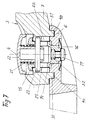
- Fig. 7
- die wesentlichen Elemente des Stielgriffes in Ansicht, im Mittellängsschnitt gesehen;
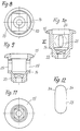
- Fig. 8 bis 12
- eine Einzelheit in unterschiedlichen Ansichten;
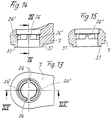
- Fig. 13 bis 15
- eine weitere Einzelheit in unterschiedlichen Ansichten.
- 1 to 3
- a tableware with handle in the use position in side view, partially cut, in top view and in bottom view (as a detail);
- 4 and 5
- a side view and a plan view of a tableware with handle handle in the rest position;
- Fig. 6
- a harness with a handle in an exploded view;
- Fig. 7
- the essential elements of the handle in view, seen in the central longitudinal section;
- 8 to 12
- a detail in different views;
- 13 to 15
- another detail in different views.
In der Zeichnung ist ein Stielgriff für ein
Geschirrteil 1, im Ausführungsbeispiel eine
Bratpfanne, gezeigt. Der Stielgriff ist
mittels eines Befestigungselementes 2 an
der Seitenwandung des Geschirrteiles 1
befestigbar. Der Stielgriff 3 oder ein
wesentlicher Teil des Stielgriffes ist um
eine Hochachse 4 aus einer vom Geschirr 1
quer abragenden Gebrauchlage (vergleiche
Figur 1 bis 3) in eine etwa parallel oder
tangential zur Geschirrwandung gerichtete
Ruhelage verschwenkbar, wie in Figur 4 und
5 in durchgezogenen Linien gezeigt, oder
auch in eine die Mündung oder Fläche des
Geschirrs 1 übergreifende Ruhelage
schwenkbar, wie in Figur 5 in
strichpunktierten Linien gezeigt ist.
Die Hochachse 4 kann parallel zur
Mittelachse 5 des Geschirrs 1 gerichtet
sein oder leicht gegenüber der Mittelachse
geneigt sein, wie insbesondere aus der
Darstellung gemäß Figur 6 ersichtlich ist.
Der Stielgriff 3 besteht vorzugsweise aus
einem an der Wandung des Geschirrs 1
befestigbaren Sockelteil 6 und einer am
Sockelteil 6 schwenkbeweglich (um die Achse
4) gehalterten Handhabe 7.In the drawing is a handle for a
Das Sockelteil 6 weist Führungsflächen 8, 9
mit ringförmiger Führungsnut 10 auf, die
zentrisch von der Schwenkachse 4 durchsetzt
ist, während die Handhabe 7 an ihrem mit
dem Sockelteil 6 verbindbaren Endbereich
eine dazu passende Führungsfläche 11 bzw.
12 mit Führungsvorsprung 13 aufweist. Die
Sollposition ist beispielsweise aus Figur 1
und Figur 4 ersichtlich Dabei sind die
ineinander greifenden und aneinander
anliegenden Führungselemente durch ein die
Schwenkachse oder Bestandteil der
Schwenkachse bildendes Verbindungsmittel
zusammengehalten.The
Bevorzugt ist die Schwenkachse 4 von einer
Lagerbuchse 14 gebildet, die mit einem
Flansch 15 sich an der Außenseite (oben)
der Handhabe 7 abstützt. Die Anordnung ist
so getroffen, daß der Flansch 15 praktisch
bündig in der Bodenseite der Handhabe 7
liegt. Die Lagerbuchse 14 durchgreift das
Sockelteil 6 und ist durch ein sich
außenseitig des Sockelteils 6 abstützendes
Befestigungsmittel fixierbar.The
Das Befestigungsmittel besteht aus einem
ringförmigen Federelement, vorzugsweise in
Form einer gewölbten Federscheibe, und
einem dieses axial durchgreifenden
Kopfbolzen 17, vorzugsweise einer
Kopfschraube, die in eine Gewindeausbildung
30 am Boden der Lagerbuchse 14
einschraubbar ist. Das als gewölbte
Federscheibe ausgebildete Federelement 16
wird in der Montagesollposition mit seinem
abgesetzten Mittelbereich 18 fest gegen die
Unterseite 19 der Buchse 14 mittels des
Befestigungsmittels 17 angezogen. Dabei
stützt sich der Randbereich des
Federelementes 16 unter Vorspannung an der
Unterseite des Sockelteil bei 20 ab. Auf
diese Weise wird trotz toleranzbehafteter
Einzelteile eine feste Fixierung der Teile
aneinander erreicht, wobei eine gewisse
Federung der Handhabe 7 gewährleistet ist
und dennoch die Drehbarkeit nicht
beeinträchtigt ist.The fastener consists of a
annular spring element, preferably in
Shape of an arched spring washer, and
one that penetrates
Der Stielgriff 3, insbesondere die Handhabe
7 ist in den beiden möglichen Extremlagen
arretierbar. Im Ausführungsbeispiel ist
dazu in die Lagerbuchse 14 an ihrem mit
Flansch 15 versehenen Ende ein Federelement
21 und ein unter Vorspannung des
Federelementes 21 axial zur Lagerbuchse 14
verschiebliches in diese eingreifendes
Bedienteil 22 in Form eines zylindrischen
Druckknopfes vorgesehen. Letzterer ist von
einem Verriegelungsstift 23 durchsetzt, der
in eine radiale Durchgangsbohrung 24 des
Bedienteiles eingesetzt werden kann. Der
Verriegelungsstift 23 durchgreift die
Lagerbuchse 14 quer zu ihrer Längsachse in
parallel zu ihrer Längsachse gerichteten
Langlöchern 25, wodurch der Stellweg in
Achsrichtung der Achse 4 des Bedienteiles
22 begrenzt ist. Der Verriegelungsstift 23
überragt die Lagerbuchse 14 radial. Mit den
radial überstehenden Enden ist der
Arretierungsstift 23 in Arretierungsnuten
26 des die Lagerbuchse 14 umgebenden
Bereiches der Handhabe 7 eingesetzt, so daß
bei entlastetem Bedienteil, wie
beispielsweise aus Figur 1 und Figur 4
ersichtlich, die Schwenkbeweglichkeit der
Handhabe 7 unterbunden ist, da die Enden
des Verriegelungsstiftes 23 in den axialen
Arretierungsnuten 26 einsitzen. Bei axial
belastetem und in Zeichnungsfigur 6 nach
unten verschobenem Bedienteil 22 sind die
Enden des Verriegelungsstiftes 23 außer
Eingriff von den axialen Arretierungsnuten
26, so daß die Handhabe 7 um die
Lagerbuchse 14 schwenkbar ist. Die
Betätigung des Bedienelementes 22 kann in
einfacher Weise von dem Benutzer erfolgen,
in dem dieser die Handhabe 7 mit der Hand
umgreift und mit dem Daumen der gleichen
Hand das Bedienelement 22 eindrückt
(betätigt).The
Die aneinander liegenden Führungsflächen 9,
11 von Sockelteil 6 und Handhabe 7 sind
dadurch besonders gleitfähig gemacht, daß
zwischen diesen Flächen Gleitscheiben 27
aus PTFE angeordnet sind.The adjacent guide surfaces 9,
11 of
Das Federelement 21 ist im
Ausführungsbeispiel als Schraubenfeder
ausgebildet, wobei die Schraubenfeder sich
einerseits an einer Schulter 28 der
Lagerbuchse 14 abstützt und andererseits an
einer entsprechenden Stützfläche 29 des
Bedienelementes 22.The
Zur Montage des Stielgriffes kann zunächst
das Befestigungselement 2 an der Wandung
des Geschirrs 1 angebracht werden oder aber
es kann zunächst die Komplettierung des
Griffes erfolgen, die nachstehend
beschrieben wird, und dann kann der
komplette Griff an der Wandung des
Geschirrteiles 1 angebracht werden. Die
Komplettierung des Stielgriffes 3 erfolgt
in folgender Weise. Es wird zunächst die
Scheibe 27 in die Nut 10 des Sockelteiles
6 eingelegt, dann die Handhabe 7 mit den
entsprechenden Passflächen aufgesetzt und
die weitere Gleitscheibe 27 aufgelegt. Die
obere Gleitscheibe 27 liegt dabei zwischen
dem Flansch 15 der Buchse 14 und der
Oberseite der Handhabe 7. Zuvor ist die
Buchse 14 durch Einsatz der Teile 21, 22
und 23 komplettiert worden. Diese Teile
sind in die Handhabe 7 lagerichtig
eingebracht. Die endgültige Fixierung
erfolgt dann durch Auflegen des
Federelementes 16 und Anbringen des
Befestigungselementes 17 (einschrauben in
die Gewindebohrung 30).To assemble the handle, you can first
the
Insbesondere in der Zeichnungsfigur 7 ist
ein Stielgriff 3 für ein Geschirr gezeigt,
der mittels eines Befestigungselementes an
der Wandung des Geschirrs befestigbar ist.
Der Stielgriff 3 ist um eine Hochachse 4
aus einer vom Geschirr quer abragenden
Gebrauchslage in eine dazu parallele oder
tangential zur Geschirrwandung gerichtete
oder in eine die Mündung oder Fläche des
Geschirrs übergreifende Ruhelage
schwenkbar. Der Stielgriff 3 besteht im
wesentlichen aus einem am Geschirr
befestigbaren Sockelteil 6 und einer am
Sockelteil schwenkbeweglich gehalterten
Handhabe 7. Das Sockelteil 6 weist eine
ringförmige Führungsnut 10 auf, die
zentrisch von der Schwenkachse durchsetzt
ist. Die Handhabe 7 weist an ihrem mit dem
Sockelteil 6 verbindbaren Endbereich eine
dazu passende Führungsfläche mit
ringförmigen Führungsvorsprung 31 auf,
wobei die ineinandergreifenden und
aneinanderliegenden Führungselemente durch
ein die Schwenkachse bildendes
Verbindungsmittel zusammengehalten sind.In particular in the figure 7 is
a
Die Schwenkachse 4 ist von einer
Lagerbuchse 14 gebildet, die mit einem
Flansch 15 an der Außenseite der Handhabe
sich abstützt. Sie durchgreift die Handhabe
7 und das Sockelteil 6 und ist durch ein
sich außenseitig des Sockelteils 6 (unten)
abstützendes Befestigungsmittel fixierbar.
Dieses Befestigungsmittel besteht aus einem
ringförmigen oder zylindrischen
Federelement 16 und einem dieses axial
durchgreifenden Befestigungsmittel in Form
eines Kopfbolzens 17, der in eine in der
Lagerbuchse 14 unverdrehbar gehalterte
Mutter 32 einschraubbar ist. Das
Federelement 16 ist eine gewölbte
Federscheibe, deren Mittelbereich abgestuft
ist und fest gegen die Unterseite der
Lagerbuchse 14 mittels des Kopfbolzens 17
anziehbar ist, während der Randbereich sich
unter Federvorspannung an der Unterseite
des Sockelteils 6 abstützt. In die
Lagerbuchse 14 ist an ihrem mit Flansch 15
versehenen Ende ein Federelement 21 und ein
unter der Vorspannung des Federelementes 21
axial zur Lagerbuchse verschiebliches
Bedienteil 22 eingesetzt, das von einem
Verriegelungsstift 23 quer durchsetzt ist.
Der Verriegelungsstift 23 durchgreift die
Lagerbuchse 14 quer zu ihrer Längsachse in
parallel zu ihrer Längsachse gerichteten
Langlöchern 25 und überragt die Lagerbuchse
14 radial mit beiden Enden. Mit diesen
Enden greift der Verriegelungsstift 23 in
axiale Arretierungsnuten 26, 26' durch die
Lagerbuchse 14 radial umgebenden Bereiches
der Lochung der Handhabe 7 ein. Hierdurch
ist bei entlastetem Bedienteil 22 die
Schwenkbeweglichkeit der Handhabe 7 in der
Gebrauchslage oder in der Ruhelage
unterbunden, während bei axial belastetem
und verschobenem Bedienteil 22 die Enden
des Verriegelungsstift es 23 unten außer
Eingriff von den axialen Arretierungsnuten
26,26' sind und die Handhabe 7 entsprechend
um die Lagerbuchse 14 schwenkbar ist.The
Vorzugsweise besteht das Sockelteil 6 und
der Handhabe 7 aus einem Duroplast,
während die Lagerbuchse 14 und
gegebenenfalls das Bedienteil 22 aus
Thermoplast besteht. Dabei ist der
Außendurchmesser der Lagerbuchse 14 in dem
in die Mittellochung der Handhabe 7 des
Stielgriffs 3 durchgreifenden Bereich mit
kleinerem Durchmesser als die Mittellochung
ausgebildet, so daß die Teile mit radialem
Spiel ineinandergreifen.Preferably, the
Das die Gewindeausbildung 32 aufweisende
Ende der Lagerbuchse 14 ist im Querschnitt
als Polygon ausgebildet. Das Polygon ist
mit 33 bezeichnet. Der Einsatzbereich in
der Lochung des Sockelteils 6 ist
formgleich ausgebildet, so daß die Teile
drehfest zueinander gehalten sind.The
Die Langlöcher 25 der Lagerbuchse 14 sind
in dem ihrer Mündung naheliegenden
Endbereich (in der Zeichnung oben) konisch
oder keilförmig eingeengt. Die Einengung
ist mit 34 bezeichnet. Hierdurch kann der
Verriegelungsstift zunächst in den
erweiterten Bereich mit Spiel eingreifen,
bevor er dann in die Einengung 34 eindringt
und damit spielfrei gehalten ist.The
Die Axialnuten 26,26' des die Lagerbuchse
14 radial umgebenden Bereichs der Handhabe
7 sind paarweise einander gegenüberliegend
angeordnet, wobei ein solches Paar von
Arretierungsnuten 26, in welches der
Verriegelungsstift 23 in der
eingeschwenkten Ruhelage mit Spiel
eingreift, durch Axialnuten gebildet ist,
die parallel verlaufende Nutflanken
aufweisen und somit eine einfache Montage
und einen mit Spiel behafteten Sitz des
Verriegelungsstiftes ermöglichen. Das
zweite Paar von Arretierungsnuten 26', in
welches der Verriegelungsstift 23 in der
ausgeschwenkten Gebrauchslage eingreift,
ist durch axial gerichtete Nuten gebildet,
die zueinander konvergierende Nutflanken
mindestens im der Griffoberseite
zugewandten Endbereich aufweisen, wie
insbesondere aus Figur 9 ersichtlich ist.
In diese Nuten kann der Verriegelungsstift
zunächst mit Spiel eingreifen, bis er dann
in den Einengungsbereich gelangt und dort
spielfrei gehalten ist. The
Die Erfindung ist nicht auf das Ausführungsbeispiel beschränkt, sondern im Rahmen der Ansprüche vielfach variabel.The invention is not based on that Embodiment limited, but in The scope of the claims is often variable.
Claims (11)
- Shank-type handle for a utensil, in particular roasting, baking or cooking utensil, which can be attached by means of an attachment element to the wall of a utensil, the shank-type handle or a substantial part of the shank-type handle being swivellable around a vertical axis from a utilization position projecting transversely from the utensil into a rest position which is directed approximately parallel or tangentially to the utensil wall or into a rest position engaging across the mouth or surface of the utensil, the shank-type handle comprising a base part which can be attached to the utensil and a handle mounted on the base part and swivellably movable, the base part having a guide surface with annular guide groove or annular guide projection, which guide surface is centrally pierced by the swivel axis, and the handle having, at its end region which is connectable to the base part, a guide surface, suitable therefor, with guide projection or guide groove, the guide elements engaging in one another and adjacent to one another being held together by a joining means which forms the swivel axis, characterized in that the swivel axis (4) is formed by a bearing bush (14) which rests by means of a flange (15) on the outside of the handle (7), engages through the handle (7) and the base part (6) and can be fixed by an attachment means resting on the outside of the base part (6), in that the attachment means comprises an annular or cylindrical spring element (16) and a setbolt (17) which engages axially through the latter, the spring element (16) being a curved spring washer whose central region can be pulled firmly against the lower side of the bearing bush (14) by means of the setbolt (17) and whose peripheral region rests under pretension on the lower side of the base part (6).
- Shank-type handle according to Claim 1, characterized in that the vertical axis (4) is directed parallel to the central axis (5) of the utensil (1) or is slightly inclined with respect to the central axis.
- Shank-type handle according to either of Claims 1 or 2, characterized in that the shank-type handle (3) can be locked in the two possible extreme positions.
- Shank-type handle according to one of Claims 1 to 3, characterized in that a spring element (21) and an operating part (22) which can be displaced axially with respect to the bearing bush while pretensioning the spring element (21) and which is transversely pierced by a locking pin (23) is inserted into the bearing bush (14) at its end provided with a flange (15), the locking pin (23) engaging through the bearing bush (14) transversely with respect to its longitudinal axis in elongated holes (25) directed parallel to its longitudinal axis and the bearing bush (14) projects radially and also engages in axial locking grooves (26) of that region of the handle (7) radially surrounding the bearing bush (14) so that, with the operating part (22) not under load, the swivelling mobility of the handle (7) into the utilization position or into the rest position is suppressed and, with the operating part (22) axially loaded and displaced, the ends of the locking pin (23) are out of engagement with the axial locking grooves (26) and the handle (7) can be swivelled around the bearing bush (14).
- Shank-type handle according to Claim 4, characterized in that the operating part (22) is a cylindrical push-button.
- Shank-type handle according to one of Claims 1 to 5, characterized in that the adjacent guide surfaces of base part (6) and handle (7) and also of the flange (15) and the handle (7) are coated with a friction-reducing material or sliding discs (27) made of such a material are disposed between the surfaces.
- Shank-type handle according to Claim 6, characterized in that the friction-reducing material is PTFE.
- Shank-type handle according to one of Claims 1-7, characterized in that the base part (6) and the handle (7) are composed of a thermoset and the bearing bush (14) is composed of a thermoplastic, the external diameter of the bearing bush (14) having a smaller diameter than the central perforation in the region engaging through the central perforation of the handle (7) of the shank-type handle (3) so that the parts engage in one another with radial play.
- Shank-type handle according to Claim 8, characterized in that that end of the bearing bush (14) which has a threaded construction (32) is formed in cross section as a polygon (33) and the insertion region is constructed in an identical shape in the perforation of the base part (6).
- Shank-type handle according to Claim 8 or 9, characterized in that the elongated holes (25) in the bearing bush (14) are tapered conically or in wedge-shape fashion at least in the end region adjacent to their mouth and the locking pin (23) engages in a play-free manner in the taper.
- Shank-type handle according to Claims 8 to 10, characterized in that the locking grooves (26, 26') of that region of the handle (7) radially surrounding the bearing bush (14) are disposed opposite one another in pairs, such a pair of locking grooves (26) in which the locking pin (23) engages in the swivelled-in rest position with play being formed by axial grooves which have groove flanks projecting in parallel, while a second pair of locking grooves (26') in which the locking pin (23) engages in the swivelled-out utilization position being formed by axially directed grooves which have mutually converging groove flanks at least in the end region adjacent to the shank upper side between which groove flanks the locking pin (23) can be introduced in a play-free manner.
Applications Claiming Priority (4)
| Application Number | Priority Date | Filing Date | Title |
|---|---|---|---|
| DE19621524A DE19621524C1 (en) | 1996-05-29 | 1996-05-29 | Cookware handle |
| DE19621524 | 1996-05-29 | ||
| DE19653228 | 1996-12-20 | ||
| DE19653228A DE19653228A1 (en) | 1996-05-29 | 1996-12-20 | Handle handle |
Publications (2)
| Publication Number | Publication Date |
|---|---|
| EP0809962A1 EP0809962A1 (en) | 1997-12-03 |
| EP0809962B1 true EP0809962B1 (en) | 1999-09-29 |
Family
ID=26026122
Family Applications (1)
| Application Number | Title | Priority Date | Filing Date |
|---|---|---|---|
| EP97107065A Expired - Lifetime EP0809962B1 (en) | 1996-05-29 | 1997-04-29 | Handle |
Country Status (10)
| Country | Link |
|---|---|
| US (1) | US6173860B1 (en) |
| EP (1) | EP0809962B1 (en) |
| JP (1) | JPH10216026A (en) |
| KR (1) | KR100289875B1 (en) |
| AT (1) | ATE185053T1 (en) |
| AU (1) | AU706490B2 (en) |
| BR (1) | BR9709276A (en) |
| DE (2) | DE19653228A1 (en) |
| TR (1) | TR199802470T2 (en) |
| WO (1) | WO1997045046A1 (en) |
Cited By (1)
| Publication number | Priority date | Publication date | Assignee | Title |
|---|---|---|---|---|
| FR2898030A1 (en) * | 2006-03-06 | 2007-09-07 | Seb Sa | GRIPPING DEVICE FOR CULINARY USTENSILE |
Families Citing this family (39)
| Publication number | Priority date | Publication date | Assignee | Title |
|---|---|---|---|---|
| ITTO980274A1 (en) * | 1998-03-27 | 1999-09-27 | Termoplastic Fbm Srl | HANDLE DEVICE FOR A COOKING CONTAINER FOR FOOD, ESPECIALLY FOR A FRYING PAN |
| US6257439B1 (en) * | 1999-12-01 | 2001-07-10 | Te Hui Hsu | Handle for a food container |
| US6439420B1 (en) * | 2001-03-29 | 2002-08-27 | Jong Peter Park | Detachable handle for cooking utensil |
| FR2883153B1 (en) * | 2005-03-17 | 2007-04-20 | Seb Sa | SWIVELING GRIPPING DEVICE FOR A CULINARY USTENSILE |
| ITMI20052289A1 (en) * | 2005-11-30 | 2007-06-01 | Ballarini Paolo & Figli Spa | WALKABLE HANDLE FOR A KITCHEN CONTAINER |
| ITMI20060233A1 (en) * | 2006-02-10 | 2007-08-11 | Ballarini Paolo & Figli Spa | RECLINABLE HANDLE FOR A PAN |
| ES1062429Y (en) * | 2006-03-10 | 2006-09-16 | Rayen Sl | PAN |
| CN100546530C (en) * | 2006-05-09 | 2009-10-07 | 陆意祥 | A kind of handle for pot |
| GB2444476A (en) * | 2006-12-06 | 2008-06-11 | Otter Controls Ltd | Crepe maker |
| US7975874B2 (en) * | 2008-08-11 | 2011-07-12 | Ian Scott | Bracket and handle for cooking vessel |
| KR100923419B1 (en) * | 2008-12-29 | 2009-10-23 | (주)드림셰프 | Kitchen utensils |
| GB2473027B (en) * | 2009-08-27 | 2011-08-03 | Spearmark Internat Ltd | A drink receptacle |
| US8276242B2 (en) * | 2010-04-09 | 2012-10-02 | Girard Mylene | Adjustable handle assembly with locking mechanism |
| FR2958519B1 (en) * | 2010-04-13 | 2013-09-13 | Seb Sa | PIVOTING HANDLE FOR COOKING CONTAINER COMPRISING A RETRACTABLE LATCH IN THE HUB |
| FR2958520B1 (en) * | 2010-04-13 | 2013-09-13 | Seb Sa | SWIVEL HANDLE FOR COOKING CONTAINER HAVING AT LEAST TWO LOCKING KEYS |
| ITBS20100139A1 (en) * | 2010-08-09 | 2012-02-10 | Bialetti Ind Spa | MOKA SUPPORT FOR INDUCTION KITCHEN TABLE |
| CN102068213B (en) * | 2010-12-07 | 2012-09-05 | 浙江苏泊尔股份有限公司 | Rotatable cooker handle |
| US9060640B2 (en) * | 2011-12-16 | 2015-06-23 | National Presto Industries, Inc. | Countertop appliance having detachable base |
| US8950621B2 (en) * | 2012-03-02 | 2015-02-10 | Charles HINZMAN | Cooking utensil with rotatable handle |
| ITMI20122066A1 (en) * | 2012-12-03 | 2014-06-04 | Sanmiro S R L | ROLLABLE TOOL KITCHEN HANDLE. |
| ITMI20122067A1 (en) * | 2012-12-03 | 2014-06-04 | Sanmiro S R L | ROLLABLE TOOL KITCHEN HANDLE. |
| WO2014165706A1 (en) * | 2013-04-04 | 2014-10-09 | Meyer Intellectual Properties Ltd. | Detachable handle and cookware vessel |
| CN103690059B (en) * | 2014-01-15 | 2016-08-17 | 浙江苏泊尔家电制造有限公司 | Baking machine |
| CN103690060B (en) * | 2014-01-15 | 2017-01-18 | 浙江苏泊尔家电制造有限公司 | Frying and baking machine |
| KR101509482B1 (en) * | 2014-05-29 | 2015-04-08 | 이동우 | Folding style handle structure in cookware |
| US20150366384A1 (en) * | 2014-06-23 | 2015-12-24 | Jeff Cates | Beverage containers |
| KR200476325Y1 (en) | 2014-07-21 | 2015-02-16 | 주식회사 로이첸 | Frying pan |
| USD751334S1 (en) * | 2014-08-04 | 2016-03-15 | X.J. Electrics (Hubei) Co., Ltd | Pan |
| CN204015936U (en) * | 2014-08-04 | 2014-12-17 | 湖北香江电器股份有限公司 | Collapsible pan |
| US10238228B2 (en) * | 2016-02-16 | 2019-03-26 | Meyer Intellectual Properties Limited | Composite cookware handle |
| EP3484333A4 (en) * | 2016-07-13 | 2019-11-27 | Sea To Summit Pty Ltd | Handle for a container, hand-tool or other like item |
| US20230322444A1 (en) * | 2022-04-06 | 2023-10-12 | Newbury Holdings, LLC | Drinking vessel with rotating handle |
| USD1047582S1 (en) | 2023-04-14 | 2024-10-22 | Sea To Summit Pty Ltd | Cookware handle mount |
| USD1047581S1 (en) | 2023-04-14 | 2024-10-22 | Sea To Summit Pty Ltd | Cookware handle |
| USD1047584S1 (en) | 2023-04-14 | 2024-10-22 | Sea To Summit Pty Ltd | Cookware handle |
| USD1083488S1 (en) * | 2023-06-26 | 2025-07-15 | Joseph Joseph, Ltd. | Cookware handle |
| CN222264946U (en) * | 2023-12-15 | 2024-12-31 | 摇斯菲尔产品有限公司 | Water cup with rotatable handle |
| USD1083489S1 (en) * | 2023-12-22 | 2025-07-15 | Joseph Joseph, Ltd. | Cookware handle |
| EP4606285A1 (en) * | 2024-02-22 | 2025-08-27 | La Termoplastic F.B.M. - S.r.l. | Handle for a cooking container |
Family Cites Families (8)
| Publication number | Priority date | Publication date | Assignee | Title |
|---|---|---|---|---|
| US66173A (en) * | 1867-06-25 | Improved handle attachment foe blacking-boxes | ||
| US1490568A (en) * | 1922-05-26 | 1924-04-15 | Koenig Remus | Combination frying pan and cooker |
| US2361417A (en) * | 1943-11-15 | 1944-10-31 | James H Reichart | Endless, self-clamping handled band |
| US3777094A (en) * | 1971-09-09 | 1973-12-04 | Environment One Corp | Thermally insulated cookware for dynamic induction field heating and cooking apparatus |
| US3838680A (en) * | 1973-07-16 | 1974-10-01 | P Shipman | Combination heating and serving assembly |
| DE8029340U1 (en) * | 1980-11-04 | 1981-03-12 | Schroff Gmbh, 7541 Straubenhardt | Articulated connection |
| US4645905A (en) * | 1985-02-27 | 1987-02-24 | Dart Industries, Inc. | Foldable household appliance |
| JPH0425097Y2 (en) * | 1986-05-27 | 1992-06-15 |
-
1996
- 1996-12-20 DE DE19653228A patent/DE19653228A1/en not_active Withdrawn
-
1997
- 1997-04-26 BR BR9709276-2A patent/BR9709276A/en not_active Application Discontinuation
- 1997-04-26 AU AU29495/97A patent/AU706490B2/en not_active Ceased
- 1997-04-26 WO PCT/DE1997/000878 patent/WO1997045046A1/en not_active Ceased
- 1997-04-26 TR TR1998/02470T patent/TR199802470T2/en unknown
- 1997-04-26 US US09/180,220 patent/US6173860B1/en not_active Expired - Fee Related
- 1997-04-29 DE DE59700491T patent/DE59700491D1/en not_active Expired - Fee Related
- 1997-04-29 EP EP97107065A patent/EP0809962B1/en not_active Expired - Lifetime
- 1997-04-29 AT AT97107065T patent/ATE185053T1/en not_active IP Right Cessation
- 1997-05-21 JP JP9166461A patent/JPH10216026A/en active Pending
- 1997-05-29 KR KR1019970021472A patent/KR100289875B1/en not_active Expired - Fee Related
Cited By (4)
| Publication number | Priority date | Publication date | Assignee | Title |
|---|---|---|---|---|
| FR2898030A1 (en) * | 2006-03-06 | 2007-09-07 | Seb Sa | GRIPPING DEVICE FOR CULINARY USTENSILE |
| WO2007101926A3 (en) * | 2006-03-06 | 2007-11-01 | Seb Sa | Holder for culinary utensil |
| AU2007222283B2 (en) * | 2006-03-06 | 2011-03-17 | Seb Sa | Holder for culinary utensil |
| US8261414B2 (en) | 2006-03-06 | 2012-09-11 | Seb Sa | Holder for culinary utensil |
Also Published As
| Publication number | Publication date |
|---|---|
| KR100289875B1 (en) | 2001-05-15 |
| BR9709276A (en) | 2000-01-11 |
| WO1997045046A1 (en) | 1997-12-04 |
| KR19980063321A (en) | 1998-10-07 |
| JPH10216026A (en) | 1998-08-18 |
| TR199802470T2 (en) | 1999-02-22 |
| AU2949597A (en) | 1998-01-05 |
| AU706490B2 (en) | 1999-06-17 |
| EP0809962A1 (en) | 1997-12-03 |
| ATE185053T1 (en) | 1999-10-15 |
| DE19653228A1 (en) | 1998-06-25 |
| US6173860B1 (en) | 2001-01-16 |
| DE59700491D1 (en) | 1999-11-04 |
Similar Documents
| Publication | Publication Date | Title |
|---|---|---|
| EP0809962B1 (en) | Handle | |
| EP0733747B1 (en) | Support for shower head | |
| DE69908006T2 (en) | Handle device for a cookware, in particular a pan | |
| DE8422413U1 (en) | Length-adjustable gas spring for a lockable lifting device for stepless adjustment of chair seats, table tops or similar pieces of furniture | |
| DE4037409C2 (en) | Swivel and swivel base for a monitor | |
| EP0641532B1 (en) | Length adjustable column for chairs, tables or the like | |
| DE29615440U1 (en) | Handheld exercise machine | |
| EP0133524B1 (en) | Lockable lifting device for the infinitely variable positioning of seats, table tops or similar articles, and lengthwise adjustable gas spring for such a lifting device | |
| EP2921077B1 (en) | Office chair | |
| EP1059051A1 (en) | Adjustable arm-rest for a chair | |
| DE1654283A1 (en) | Height adjustment device for swivel chairs | |
| DE9006484U1 (en) | Operating handle | |
| DE69118661T2 (en) | Device for attaching a raised toilet seat to the bowl of the toilet | |
| DE3710883C2 (en) | Door fitting with door operating element and door plate | |
| DE19621524C1 (en) | Cookware handle | |
| DE3238889C2 (en) | ||
| DE60200832T2 (en) | TABLE WITH AT LEAST ONLY A TURNOVER EXTENDED BY TURNING | |
| EP0001283A1 (en) | Braked castor for movable apparatus, especially refuse or similar containers | |
| DE2729880A1 (en) | Garden umbrella adjustable shelf - has slot for fitting onto umbrella stem, holding special clamp for height adjustment | |
| EP0133523A2 (en) | Lengthwise adjustable gas spring for a lockable lifting device for the infinitely variable positioning of seats, table tops or the like | |
| DE69205276T2 (en) | FASTENING DEVICE FOR ARMRESTS. | |
| CH716756B1 (en) | Assembly device for the detachable assembly of a set on a toilet body. | |
| DE19743596C3 (en) | Table with a table top | |
| DE8333532U1 (en) | table | |
| CH718420B1 (en) | Tableware holder |
Legal Events
| Date | Code | Title | Description |
|---|---|---|---|
| PUAI | Public reference made under article 153(3) epc to a published international application that has entered the european phase |
Free format text: ORIGINAL CODE: 0009012 |
|
| AK | Designated contracting states |
Kind code of ref document: A1 Designated state(s): AT DE DK FR GB GR IT |
|
| 17P | Request for examination filed |
Effective date: 19971213 |
|
| GRAG | Despatch of communication of intention to grant |
Free format text: ORIGINAL CODE: EPIDOS AGRA |
|
| GRAG | Despatch of communication of intention to grant |
Free format text: ORIGINAL CODE: EPIDOS AGRA |
|
| GRAH | Despatch of communication of intention to grant a patent |
Free format text: ORIGINAL CODE: EPIDOS IGRA |
|
| 17Q | First examination report despatched |
Effective date: 19980911 |
|
| GRAH | Despatch of communication of intention to grant a patent |
Free format text: ORIGINAL CODE: EPIDOS IGRA |
|
| GRAA | (expected) grant |
Free format text: ORIGINAL CODE: 0009210 |
|
| AK | Designated contracting states |
Kind code of ref document: B1 Designated state(s): AT DE DK FR GB GR IT |
|
| PG25 | Lapsed in a contracting state [announced via postgrant information from national office to epo] |
Ref country code: GR Free format text: LAPSE BECAUSE OF NON-PAYMENT OF DUE FEES Effective date: 19990929 |
|
| REF | Corresponds to: |
Ref document number: 185053 Country of ref document: AT Date of ref document: 19991015 Kind code of ref document: T |
|
| REF | Corresponds to: |
Ref document number: 59700491 Country of ref document: DE Date of ref document: 19991104 |
|
| ET | Fr: translation filed | ||
| ITF | It: translation for a ep patent filed | ||
| PG25 | Lapsed in a contracting state [announced via postgrant information from national office to epo] |
Ref country code: DK Free format text: LAPSE BECAUSE OF FAILURE TO SUBMIT A TRANSLATION OF THE DESCRIPTION OR TO PAY THE FEE WITHIN THE PRESCRIBED TIME-LIMIT Effective date: 19991229 |
|
| GBT | Gb: translation of ep patent filed (gb section 77(6)(a)/1977) |
Effective date: 19991209 |
|
| PLBE | No opposition filed within time limit |
Free format text: ORIGINAL CODE: 0009261 |
|
| STAA | Information on the status of an ep patent application or granted ep patent |
Free format text: STATUS: NO OPPOSITION FILED WITHIN TIME LIMIT |
|
| 26N | No opposition filed | ||
| PGFP | Annual fee paid to national office [announced via postgrant information from national office to epo] |
Ref country code: GB Payment date: 20010423 Year of fee payment: 5 |
|
| PGFP | Annual fee paid to national office [announced via postgrant information from national office to epo] |
Ref country code: AT Payment date: 20010427 Year of fee payment: 5 |
|
| REG | Reference to a national code |
Ref country code: GB Ref legal event code: IF02 |
|
| PG25 | Lapsed in a contracting state [announced via postgrant information from national office to epo] |
Ref country code: GB Free format text: LAPSE BECAUSE OF NON-PAYMENT OF DUE FEES Effective date: 20020429 Ref country code: AT Free format text: LAPSE BECAUSE OF NON-PAYMENT OF DUE FEES Effective date: 20020429 |
|
| GBPC | Gb: european patent ceased through non-payment of renewal fee |
Effective date: 20020429 |
|
| PGFP | Annual fee paid to national office [announced via postgrant information from national office to epo] |
Ref country code: FR Payment date: 20040212 Year of fee payment: 8 |
|
| PG25 | Lapsed in a contracting state [announced via postgrant information from national office to epo] |
Ref country code: IT Free format text: LAPSE BECAUSE OF NON-PAYMENT OF DUE FEES Effective date: 20050429 |
|
| PG25 | Lapsed in a contracting state [announced via postgrant information from national office to epo] |
Ref country code: FR Free format text: LAPSE BECAUSE OF NON-PAYMENT OF DUE FEES Effective date: 20051230 |
|
| REG | Reference to a national code |
Ref country code: FR Ref legal event code: ST Effective date: 20051230 |
|
| PGFP | Annual fee paid to national office [announced via postgrant information from national office to epo] |
Ref country code: DE Payment date: 20080623 Year of fee payment: 12 |
|
| PG25 | Lapsed in a contracting state [announced via postgrant information from national office to epo] |
Ref country code: DE Free format text: LAPSE BECAUSE OF NON-PAYMENT OF DUE FEES Effective date: 20091103 |