EP0809566B1 - Fabrication d'un preservatif - Google Patents
Fabrication d'un preservatif Download PDFInfo
- Publication number
- EP0809566B1 EP0809566B1 EP96943016A EP96943016A EP0809566B1 EP 0809566 B1 EP0809566 B1 EP 0809566B1 EP 96943016 A EP96943016 A EP 96943016A EP 96943016 A EP96943016 A EP 96943016A EP 0809566 B1 EP0809566 B1 EP 0809566B1
- Authority
- EP
- European Patent Office
- Prior art keywords
- section
- plunger tool
- prophylactic
- shaped
- narrowing
- Prior art date
- Legal status (The legal status is an assumption and is not a legal conclusion. Google has not performed a legal analysis and makes no representation as to the accuracy of the status listed.)
- Expired - Lifetime
Links
- 230000000069 prophylactic effect Effects 0.000 title claims abstract description 57
- 238000004519 manufacturing process Methods 0.000 title abstract description 13
- 230000007704 transition Effects 0.000 claims abstract description 15
- 238000000034 method Methods 0.000 claims description 15
- 239000013013 elastic material Substances 0.000 claims description 12
- 238000001035 drying Methods 0.000 claims description 8
- XLYOFNOQVPJJNP-UHFFFAOYSA-N water Substances O XLYOFNOQVPJJNP-UHFFFAOYSA-N 0.000 claims description 8
- 238000007654 immersion Methods 0.000 claims description 2
- 238000005096 rolling process Methods 0.000 claims 1
- 238000009827 uniform distribution Methods 0.000 claims 1
- 229910003460 diamond Inorganic materials 0.000 abstract description 15
- 239000010432 diamond Substances 0.000 abstract description 15
- 230000009189 diving Effects 0.000 description 50
- 238000000227 grinding Methods 0.000 description 17
- 239000004816 latex Substances 0.000 description 6
- 229920000126 latex Polymers 0.000 description 6
- 239000000463 material Substances 0.000 description 5
- 238000010586 diagram Methods 0.000 description 2
- 238000007598 dipping method Methods 0.000 description 2
- 210000003899 penis Anatomy 0.000 description 2
- 238000007493 shaping process Methods 0.000 description 2
- 244000043261 Hevea brasiliensis Species 0.000 description 1
- 230000006978 adaptation Effects 0.000 description 1
- 230000009286 beneficial effect Effects 0.000 description 1
- 230000001680 brushing effect Effects 0.000 description 1
- 239000000919 ceramic Substances 0.000 description 1
- 238000004140 cleaning Methods 0.000 description 1
- 150000001875 compounds Chemical class 0.000 description 1
- 230000007812 deficiency Effects 0.000 description 1
- 229920001971 elastomer Polymers 0.000 description 1
- 238000005516 engineering process Methods 0.000 description 1
- 239000003822 epoxy resin Substances 0.000 description 1
- 238000005530 etching Methods 0.000 description 1
- 230000000763 evoking effect Effects 0.000 description 1
- 230000002349 favourable effect Effects 0.000 description 1
- 239000011521 glass Substances 0.000 description 1
- 229920003052 natural elastomer Polymers 0.000 description 1
- 229920001194 natural rubber Polymers 0.000 description 1
- 210000000056 organ Anatomy 0.000 description 1
- 238000004806 packaging method and process Methods 0.000 description 1
- 239000004033 plastic Substances 0.000 description 1
- 229920000647 polyepoxide Polymers 0.000 description 1
- 229910052573 porcelain Inorganic materials 0.000 description 1
- 229940043274 prophylactic drug Drugs 0.000 description 1
- 239000000126 substance Substances 0.000 description 1
Images


Classifications
-
- B—PERFORMING OPERATIONS; TRANSPORTING
- B29—WORKING OF PLASTICS; WORKING OF SUBSTANCES IN A PLASTIC STATE IN GENERAL
- B29C—SHAPING OR JOINING OF PLASTICS; SHAPING OF MATERIAL IN A PLASTIC STATE, NOT OTHERWISE PROVIDED FOR; AFTER-TREATMENT OF THE SHAPED PRODUCTS, e.g. REPAIRING
- B29C41/00—Shaping by coating a mould, core or other substrate, i.e. by depositing material and stripping-off the shaped article; Apparatus therefor
- B29C41/02—Shaping by coating a mould, core or other substrate, i.e. by depositing material and stripping-off the shaped article; Apparatus therefor for making articles of definite length, i.e. discrete articles
- B29C41/14—Dipping a core
-
- A—HUMAN NECESSITIES
- A61—MEDICAL OR VETERINARY SCIENCE; HYGIENE
- A61F—FILTERS IMPLANTABLE INTO BLOOD VESSELS; PROSTHESES; DEVICES PROVIDING PATENCY TO, OR PREVENTING COLLAPSING OF, TUBULAR STRUCTURES OF THE BODY, e.g. STENTS; ORTHOPAEDIC, NURSING OR CONTRACEPTIVE DEVICES; FOMENTATION; TREATMENT OR PROTECTION OF EYES OR EARS; BANDAGES, DRESSINGS OR ABSORBENT PADS; FIRST-AID KITS
- A61F6/00—Contraceptive devices; Pessaries; Applicators therefor
- A61F6/02—Contraceptive devices; Pessaries; Applicators therefor for use by males
- A61F6/04—Condoms, sheaths or the like, e.g. combined with devices protecting against contagion
-
- B—PERFORMING OPERATIONS; TRANSPORTING
- B29—WORKING OF PLASTICS; WORKING OF SUBSTANCES IN A PLASTIC STATE IN GENERAL
- B29C—SHAPING OR JOINING OF PLASTICS; SHAPING OF MATERIAL IN A PLASTIC STATE, NOT OTHERWISE PROVIDED FOR; AFTER-TREATMENT OF THE SHAPED PRODUCTS, e.g. REPAIRING
- B29C33/00—Moulds or cores; Details thereof or accessories therefor
- B29C33/42—Moulds or cores; Details thereof or accessories therefor characterised by the shape of the moulding surface, e.g. ribs or grooves
-
- B—PERFORMING OPERATIONS; TRANSPORTING
- B29—WORKING OF PLASTICS; WORKING OF SUBSTANCES IN A PLASTIC STATE IN GENERAL
- B29C—SHAPING OR JOINING OF PLASTICS; SHAPING OF MATERIAL IN A PLASTIC STATE, NOT OTHERWISE PROVIDED FOR; AFTER-TREATMENT OF THE SHAPED PRODUCTS, e.g. REPAIRING
- B29C41/00—Shaping by coating a mould, core or other substrate, i.e. by depositing material and stripping-off the shaped article; Apparatus therefor
- B29C41/02—Shaping by coating a mould, core or other substrate, i.e. by depositing material and stripping-off the shaped article; Apparatus therefor for making articles of definite length, i.e. discrete articles
- B29C41/22—Making multilayered or multicoloured articles
Definitions
- the present invention is concerned with manufacturing a shaped prophylactic with special curves, at on the one hand the special shape of the diving tool and on the other hand the manufacturing process play an important role.
- a prophylactic is made that consists of an elongated, cylindrical shaft with a through an S-shaped section and closed an adjoining reservoir part End exists. It is a recess that is in use comes to rest in the area of the glans, provided that two truncated cones abutting the small top surfaces is formed. The depression has an opening angle in the range between 60 ° and 120 °.
- the well-known prophylactic is made by immersing three times in a latex solution. There is a drying oven between each dive run through and at the end of the last drying process the known prophylactic by means of counter-rotating Brushed stripped.
- the diving tool becomes three for difficult shapes Submersible dives.
- the three dives are special important for shapes that are in certain parts of the Have relatively small radii of curvature, so that at these small radii of curvature the elastic to be applied Material (latex) is distributed unevenly, in which the cause of tears and breaks is often to be found and the prophylactic does not meet the requirements of the testing authorities corresponds.
- CH 96564 From CH 96564 is a short condom with a club-like Reservoir part known that glued to a user's penis must become. No measures are disclosed in CH 96564 from which it emerges that the club-like reservoir part due to compressive and tensile stresses caused by a special Shaping is evoked, in an upright position of use stands up.
- the aim of the present invention is to provide a novel prophylactic to protect with distinctive shapes in the upper part, the radii of curvature of the individual curves at the predetermined Make a crucial role that the internal compressive and tensile stresses of the prophylactic both in decisively influence the rolled up as well as the unrolled state.
- Another embodiment according to the invention is characterized in that that the depression is close to the closest Diameter (D5) has at least one annular groove, so that this creates at least one ring on the finished prophylactic, whose mass is much larger than the mass of the elastic material in its environment.
- Beneficial for that prophylactic according to the invention are two such ring grooves, which are about 1.5 mm apart.
- the so-called reservoir part arranged at the upper end which is designed like a club according to the invention.
- this reservoir part has the property that after pulling it out of the sales packaging stands upright in the direction of use.
- This erection of the reservoir part is in the rolled-up state of the prophylactic only possible if within the prophylactic by Shaping in the molded section of the prophylactic train and Compressive stresses arise which are directed so that the reservoir part in the direction of use with its central axis perpendicular stands at the level of the rolled up prophylactic.
- the transition of the largest diameter of the plunger in the molded section not steep and straight to the reservoir part, but represents a downward sloping S-curve.
- the diving tool Due to the shape of the diving tool according to the invention it is possible to produce an inventive method to provide the prophylactic, in which the diving tool rotating in two dives around its longitudinal axis at a certain angle to the surface to be applied elastic material (latex) is immersed. After the Dipping is a drying process in a special one Drying oven provided.
- the method for producing the prophylactic is to that the diving tool with the help of ring grooves on the surface at least one disc-shaped fine-grained diamond grinding point be ground in, the angle ( ⁇ ) between 60 ° and 120 °, with the front part of the diamond grinding tip has bluntness. This dullness is particularly necessary so that the ring groove to be created on the Surface of the diving tool has no sharp edges, in which the elastic material settles during the diving process can, which would require special cleaning processes.
- An embodiment of the ring grooves is to be designed so that it runs symmetrically to the central axis of the annular groove.
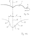
- the ring grooves are asymmetrical to the central axis be shaped such that the wall of the ring groove on the left of the axis (in Fig. 11) steeper than the wall to the right of the axis runs.
- An important aspect in the asymmetry of the ring groove can be seen in the fact that the ratio of the distances (A, A ') to the central axis of the annular groove is approximately 1: 2. This is a favorable course of the latex to be applied or another guaranteed elastic material.
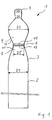
- Fig. 1 is a schematic representation of the diving tool 1 shown in a side view.
- the diving tool is made of glass. But just as well the diving tool can be made of another material such as for example porcelain, plastic, ceramic or the like are manufactured.
- the diving tool 1 sits down schematically from an elongated cylindrical part 2 and an upper one molded part 3 together.
- the diameter D1 of the cylindrical Part 2 is approximately 34 mm.
- On the elongated lower ones cylindrical part 2 closes the upper molded part 3 without a recognizable transition. The transition from the cylindrical to the molded part is done with a proportion large radius of curvature.
- the upper molded part 3 of the diving tool 1 is made up of three main components together.
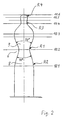
- the diameter D2 of the truncated cone 9 practically begins the transition to the so-called Reservoir part 4. Because of the importance of the transition this is described in more detail below.
- the diameter D3 of the The entrance of the reservoir part is slightly smaller than that Diameter D4 in the upper area of the reservoir part 4.
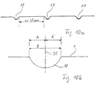
- this can be in the vicinity of the narrowest point of the recess 6 have at least one ring groove or a ring.
- the ring grooves 17, 18 are about 1.5 mm apart spaced.
- the dimension planes 10 are imaginary lines, for the dimensioning of the diving tool 1 of this embodiment are necessary.
- the dimension level 10.3 runs by the diameter D2, which is about 34 mm.
- the dimension line 10.6 represents the end of the diving tool 1 represents what corresponds to the end of the reservoir part 4.
- a convenient measure of the overall length of the molded Part 3 of the diving tool 1 is approximately 100 mm and extends from dimension level 10.1 to dimension level 10.6.
- the Dimension for the distance of the dimension plane 10.1 to the dimension plane 10.2 approx. 33 mm and the measure for the distance of level 10.2 to Level 10.4 is around 50 mm.
- the measure of the distance of the Dimension level 10.4 to dimension level 10.6 is approx. 16 mm.
- the opening angles of the truncated cones are different, whereby the lower truncated cone 8 has an opening angle of 40 ° and the upper opening angle of the truncated cone 9 is 50 °.
- the Radius of curvature R1 is 18 mm in the present case, the Radius of curvature R2 is ⁇ 25 mm.
- the radius of curvature R4 at the upper end of the reservoir part 4 is 6.5 mm.
- the total length of the reservoir part from the Dimension level 10.4 to dimension line 10.6 is 16 mm.
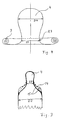
- Fig. 3 shows the uppermost part of the diving tool 1, i.e. the Reservoir part 4 with the important transitions in diameter D2 to the lower diameter D3 of the lower part of the reservoir part 4.
- Important and according to the invention is both the special here Shape of the club-like reservoir part 4 as well the transition 15, which is not steep, as in the prior art may run, as indicated by the dashed line 14 is, but must be a curved S-curve line describe what ultimately tensions rolled up in the finished Prophylactic generated and the reservoir part 4 upright to the level of the rolled up prophylactic.
- a rolled-up prophylactic is shown schematically. Due to the special shape of the transition 15 and the radii of curvature R3 in the vicinity of the diameter D3 of the Reservoir part 4 occur there due to the bias by the Roll ring 7 of the rolled up prophylactic tensions on which are directed so that the reservoir part 4 in the unpacked Condition is upright in the direction of use.
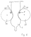
- Fig. 5 is a device for mass production of a prophylactic shown schematically.
- the total length of this System from one deflection wheel 19 to another 22 is approximately 30 m.
- the diving tool 1 is with a not to be described in detail Mechanism attached to an endless conveyor belt 16 so that the diving tool 1 at a certain speed goes through individual process steps. These are in the described above WO 95/25622 described in more detail. It is important in the method according to the invention that here only two dives in plunge pools 10 and 13 be performed. After the diving tool 1 rotates was passed through the plunge pool 10, drying takes place in the device 23 by the diving tool 1 in horizontal Position is rotated.
- the vulcanizing line 31 is an elongated oven that is almost extends over the entire length of the system.
- the stripping device for the finished Prophylactic represented by diving tool 1.
- diving tool 1 On the Diving tool 1 act two counter rotating brushes 25, 26 and slide down the prophylactic. Because of the extremely small diameter D5 at the narrowest point of the recess 6 it is difficult to use only the brushes 25, 26 to strip the finished prophylactic from the diving tool 1.
- the solution to this difficulty is that behind the Rollring 7 formed at least one water jet 27, 28 so acts on the diving tool 1 that between the prophylactic and forms a light film of water on the diving tool, which makes it possible to strip off the prophylactic.
- the water jet 27, 28 can be pulsed or continuous act on the diving tool.
- Fig. 7 the cross section of a round is schematically Grinding wheel 30 shown, on the periphery of a sintered Diamond attachment 31 is applied.
- the carrier disk 30 is about 10 mm thick and has a diameter of about 200 mm.
- the material of the carrier disc can be a hardened armored Epoxy resin, but other suitable materials can can also be used for this.
- On the periphery of the Carrier disc 30 is located along the circumference of the sintered Diamond attachment 31 with the diamond grinding tip according to the invention 32.
- the diamond attachment 31 has one at the end Tip with a certain angle ( ⁇ ), which in Fig. 8 in enlarged scale is shown.
- the angle ⁇ is in general choose between 60 ° and 120 °, depending on the type an annular groove is required.
- a corresponding cross-sectional shape to be given is the upper part 33 of the diamond grinding tip 32 slightly blunted so that the edges 34 of the grinding tip are round.
- Fig. 9 is another embodiment of the diamond attachment 31 shown in cross section.
- ring grooves 17, 18 it is advisable to use several diamond grinding tips 32 to be arranged on an attachment 31. With such an essay five ring grooves 17 could thus be produced in one grinding process become. This shortens the working time many times over for the production of the required ring grooves 17, 18.
- the grit of the grinding tips 32 must be relatively fine be so that no grooves are drawn into the ring groove, in which the elastic material sticks. Typical grits for this are, for example, D10, D20 to D60.
- 11a is the upper molded part of a plunger tool 1 shown in half.
- an asymmetrical annular groove 34 according to the invention, ground in with the diamond grinding tip 32 according to the invention has been.
- the asymmetry of this annular groove 34 relates on an imaginary central axis 35, which is perpendicular to the longitudinal axis of the diving tool 1.
- the characteristic one this asymmetrical annular groove 34 are different Slopes of the walls 36, 37 delimiting the annular groove (see FIG. llb).
Claims (12)
- Outil a immergé (1) pour la fabrication d'un prophelactic avec une queue cylindrique en longueur (2) avec une section moulée en s (3) et, dans le prolongement, une partie renflée réservoir (4) sur la partie fermée, la partie moulée (3) présentant un évidement (6) formé par deux bouts sphériques (8, 9) venant s'effleurer dans la partie de recouvrement de plus petite surface, l'inclinaison de la surface de l'outil immergé (1) dans le sens de la longueur étant constante, caractérisé en ce quele diamètre (D5) de l'outil immergé (1) est de 15 à 25 mm dans la partie la plus étroite de l'évidement (6) ;le rayon de courbure (R1) de la partie la plus étroite (D5) de l'évidement (6) est de 17 à 20 mm ;l'angle d'ouverture du bout sphérique (9) supérieur, ouvert vers la partie réservoir (4), est de 50° ;l'angle d'ouverture du bout sphérique inférieur (8) est de 40° ;l'angle d'ouverture de la transition entre la partie cylindrique (2) et l'évidement (6) dans la partie moulée (3) est convexe et supérieure à 25 mm ;la longueur totale de l'évidement (6) jusqu'à l'entrée dans la partie réservoir (4) est de 45 mm à 65 mm ;le plus grand diamètre (D2) de la section moulée (3) dans la zone entre l'évidement (6) et la zone d'entrée dans la partie réservoir (4) est de 33 à 35 mm.
- Outil a immergé (1) pour la fabrication d'un protecteur avec une queue cylindrique en longueur (2) avec une section moulée en s (3) et, dans le prolongement, une partie renflée réservoir (4) sur la partie fermée, la partie moulée (3) présentant un évidement (6) formé par deux bouts sphériques (8, 9) venant s'effleurer dans la partie de recouvrement de plus petite surface, l'inclinaison de la surface de l'outil immergé (1) dans le sens de la longueur étant constante, caractérisé en ce quele rayon de courbure (R3) concave dans la zone de transition (15) entre la partie réservoir (4) et la partie moulée (3) est supérieur ou égal à 12 mm ;la tangente (15') au point d'inversion de la courbe en s dans la zone de transition (15) entre la partie réservoir (4) et la partie moulée (3) forme un angle β entre 40° et 75° par rapport à la verticale.
- Outil a immergé selon la revendication 2, caractérisé en ce que le diamètre (D3) dans la zone d'entrée de la partie réservoir (4) est de 6 mm à 11 mm dans la partie inférieure et que le diamètre maximal (D4) de la partie réservoir (4) est de 11 à 14 mm.
- Outil immergé selon la revendication 2, caractérisé en ce que le rayon de courbure (R4) de la zone de l'extrémité fermée de la partie réservoir (4) est de 6 mm approximativement.
- Outil immergé selon la revendication 2, caractérisé en ce que le profil courbe de la partie réservoir renflée (4) facilite la distribution régulière du matériau élastique devant être appliqué.
- Outil immergé selon l'une des revendications précédentes, caractérisé en ce qu'au moins une rainure circulaire (17, 18) est aménagée dans la partie de plus faible diamètre (D5) de l'évidement (6).
- Outil immergé selon la revendication 6, caractérisé en ce que dans le cas de plus d'une rainure circulaire (17, 18) l'écart entre les rainures circulaires (17, 18) est d'approximativement 1,5 mm.
- Outil immergé selon l'une des revendications précédentes, caractérisé en ce que les rainures circulaires (17, 18) ont une géométrie symétrique par rapport à l'axe médian (35).
- Outil immergé selon l'une des revendications précédentes, caractérisé en ce que les rainures circulaires (34) ont une géométrie asymétrique par rapport à l'axe médian (35), de manière que la paroi (36) de la rainure circulaire (34) présente une plus forte inclinaison à gauche de l'axe (35) que la paroi (37) à droite de l'axe (35).
- Outil immergé selon l'une des revendications ci-dessus, caractérisé en ce que les écarts (A, A') de la rainure circulaire (34) par rapport à l'axe médian (35) sont dans une proportion A:A' de 1:2 approximativement.
- Procédé pour la fabrication d'un protecteur, le protecteur étant constitué d'une queue cylindrique (2) avec une section moulée en forme de s (3) et une partie
réservoir (4) dans la section d'extrémité en prolongement et une pièce moulée à paroi mince en matériau souple qui est adaptée extérieurement dans les bains d'immersion à un outil a immergé adapté à la forme du protecteur et qui racle le protecteur assemblé au moyen de brosses animées d'un mouvement rotatif de sens contraire (25, 26) et au moins un jet d'eau (27, 28) dirigé contre l'outil a immergé (1), caractérisé en ce quel'outil immergé (1) est plongé dans le matériau souple devant être adapté en deux phases d'immersion (10, 11) par rotation dans le sens axial en position oblique par rapport à la surface du matériau souple ; etune phase de séchage (23, 24) est prévue après chaque phase d'immersion (10, 13). - Procédé selon la revendication 8, caractérisé en ce qu'au moins un jet d'eau (27, 28) est orienté de telle manière qu'il soit appliqué directement contre l'outil immergé (1) derrière la bague rotative (7) pendant le raclage.
Applications Claiming Priority (3)
| Application Number | Priority Date | Filing Date | Title |
|---|---|---|---|
| DE19546985 | 1995-12-15 | ||
| DE19546985A DE19546985C1 (de) | 1995-12-15 | 1995-12-15 | Herstellung eines Prophylaktikums |
| PCT/DE1996/002405 WO1997022454A1 (fr) | 1995-12-15 | 1996-12-15 | Fabrication d'un preservatif |
Publications (2)
| Publication Number | Publication Date |
|---|---|
| EP0809566A1 EP0809566A1 (fr) | 1997-12-03 |
| EP0809566B1 true EP0809566B1 (fr) | 2001-04-25 |
Family
ID=7780293
Family Applications (1)
| Application Number | Title | Priority Date | Filing Date |
|---|---|---|---|
| EP96943016A Expired - Lifetime EP0809566B1 (fr) | 1995-12-15 | 1996-12-15 | Fabrication d'un preservatif |
Country Status (13)
| Country | Link |
|---|---|
| US (1) | US6126880A (fr) |
| EP (1) | EP0809566B1 (fr) |
| JP (1) | JPH11500677A (fr) |
| KR (1) | KR19980702269A (fr) |
| AT (1) | ATE200755T1 (fr) |
| AU (1) | AU1189697A (fr) |
| CZ (1) | CZ270697A3 (fr) |
| DE (3) | DE19546985C1 (fr) |
| ES (1) | ES2159772T3 (fr) |
| HU (1) | HUP0204414A2 (fr) |
| PL (1) | PL182060B1 (fr) |
| RU (1) | RU2189312C2 (fr) |
| WO (1) | WO1997022454A1 (fr) |
Families Citing this family (9)
| Publication number | Priority date | Publication date | Assignee | Title |
|---|---|---|---|---|
| US6135112A (en) * | 1998-02-10 | 2000-10-24 | Carter-Wallace, Inc. | Non-slip condom |
| FR2781917B1 (fr) * | 1998-07-28 | 2000-09-08 | Commissariat Energie Atomique | Procede de realisation collective de tetes magnetiques integrees a surface portante de hauteur determinee |
| US6095145A (en) * | 1999-01-12 | 2000-08-01 | Sadlo; Frank C. | Prophylactic |
| US20050076917A1 (en) * | 2003-10-10 | 2005-04-14 | Biofilm Ip, Llc. | Lubricated condom |
| CN100528522C (zh) * | 2007-08-13 | 2009-08-19 | 郝新明 | 一种特种安全套模具 |
| WO2009125239A1 (fr) * | 2008-04-08 | 2009-10-15 | Dan Icyk | Baganal preservative |
| ES2633745B1 (es) * | 2016-02-24 | 2018-06-29 | Nupseguro 2015 S.L. | Molde para fabricación por moldeo de preservativos especiales y procedimiento de fabricación que utiliza dicho molde |
| JPWO2019207793A1 (ja) * | 2018-04-27 | 2021-04-30 | 不二ラテックス株式会社 | 破裂耐久性に優れる弾性変形可能な容器 |
| USD1018829S1 (en) | 2020-10-23 | 2024-03-19 | Church & Dwight Co., Inc. | Condom |
Family Cites Families (18)
| Publication number | Priority date | Publication date | Assignee | Title |
|---|---|---|---|---|
| DE254211C (fr) * | ||||
| CH96564A (fr) * | 1921-06-01 | 1922-10-16 | Guillod Albert | Condom. |
| AT123532B (de) * | 1929-06-06 | 1931-06-25 | Marie Kochmann | Präservativ. |
| US2021299A (en) * | 1930-01-20 | 1935-11-19 | John R Gammeter | Method and apparatus for making dipped rubber articles |
| US1923733A (en) * | 1931-09-17 | 1933-08-22 | Edward S Killian | Apparatus for manufacturing thin rubber articles |
| US2968134A (en) * | 1959-10-09 | 1961-01-17 | Du Pont | Manufacture of precision cones |
| DE1603807C3 (de) * | 1966-01-21 | 1975-07-24 | Hilti Ag, Schaan (Liechtenstein) | Verankerungsstift mit Führungsrondelle |
| DE1766519A1 (de) * | 1968-06-07 | 1972-03-23 | Kadel Fritz | Praeservativ |
| DE2459473A1 (de) * | 1974-12-16 | 1976-06-24 | Experimentanlnyj Nii Metallore | Abziehwerk zum abziehen eines scheibenfoermigen schleifwerkzeugs |
| JPS61136762A (ja) * | 1984-12-10 | 1986-06-24 | Toshiba Corp | 粗球体製造方法 |
| JP2562597B2 (ja) * | 1987-03-27 | 1996-12-11 | 京セラ株式会社 | ワイヤソ− |
| US4903679A (en) * | 1988-10-14 | 1990-02-27 | Westinghouse Electric Corp. | Dressing of grinding wheels |
| CA2058210C (fr) * | 1991-12-20 | 1995-02-14 | Clive C. Solomons | Methode de formation d'une membrane, en particulier d'une membrane de latex dotee d'un biocide |
| US5409416A (en) * | 1992-09-01 | 1995-04-25 | Glass Unlimited | Sheet of glass with groove pattern to provide decorative visual effect |
| DK0676942T3 (da) * | 1992-12-17 | 1997-04-01 | Thomas Scholl | Præservativ |
| US5323544A (en) * | 1993-01-22 | 1994-06-28 | Ansell Incorporated | Method and apparatus for drying coatings or films |
| DE4409449C1 (de) * | 1994-03-19 | 1995-08-10 | Thomas Scholl | Verfahren und Vorrichtung zur Herstellung eines Prophylaktikums |
| DE4434701A1 (de) * | 1994-03-19 | 1996-04-04 | Thomas Scholl | Verfahren und Vorrichtung zur Herstellung eines Prophylaktikums |
-
1995
- 1995-12-15 DE DE19546985A patent/DE19546985C1/de not_active Expired - Fee Related
-
1996
- 1996-12-15 AU AU11896/97A patent/AU1189697A/en not_active Abandoned
- 1996-12-15 PL PL96321888A patent/PL182060B1/pl not_active IP Right Cessation
- 1996-12-15 RU RU97115715/12A patent/RU2189312C2/ru not_active IP Right Cessation
- 1996-12-15 DE DE59606825T patent/DE59606825D1/de not_active Expired - Fee Related
- 1996-12-15 EP EP96943016A patent/EP0809566B1/fr not_active Expired - Lifetime
- 1996-12-15 HU HU0204414A patent/HUP0204414A2/hu unknown
- 1996-12-15 KR KR1019970705666A patent/KR19980702269A/ko not_active Application Discontinuation
- 1996-12-15 US US08/894,348 patent/US6126880A/en not_active Expired - Fee Related
- 1996-12-15 ES ES96943016T patent/ES2159772T3/es not_active Expired - Lifetime
- 1996-12-15 AT AT96943016T patent/ATE200755T1/de not_active IP Right Cessation
- 1996-12-15 DE DE19681126T patent/DE19681126D2/de not_active Expired - Fee Related
- 1996-12-15 JP JP9522419A patent/JPH11500677A/ja active Pending
- 1996-12-15 CZ CZ972706A patent/CZ270697A3/cs unknown
- 1996-12-15 WO PCT/DE1996/002405 patent/WO1997022454A1/fr not_active Application Discontinuation
Also Published As
| Publication number | Publication date |
|---|---|
| PL321888A1 (en) | 1997-12-22 |
| JPH11500677A (ja) | 1999-01-19 |
| US6126880A (en) | 2000-10-03 |
| WO1997022454A1 (fr) | 1997-06-26 |
| MX9706266A (es) | 1998-08-30 |
| HUP0204414A2 (en) | 2003-03-28 |
| DE19681126D2 (de) | 1998-07-23 |
| AU1189697A (en) | 1997-07-14 |
| RU2189312C2 (ru) | 2002-09-20 |
| ATE200755T1 (de) | 2001-05-15 |
| EP0809566A1 (fr) | 1997-12-03 |
| DE59606825D1 (de) | 2001-05-31 |
| KR19980702269A (ko) | 1998-07-15 |
| DE19546985C1 (de) | 1997-01-16 |
| ES2159772T3 (es) | 2001-10-16 |
| CZ270697A3 (cs) | 1998-01-14 |
| PL182060B1 (pl) | 2001-10-31 |
Similar Documents
| Publication | Publication Date | Title |
|---|---|---|
| DE10219983B4 (de) | Verfahren zum Herstellen von Produkten durch Freiform-Lasersintern | |
| EP1046426A2 (fr) | Buse de pulvérisation haute pression | |
| DE8012313U1 (de) | Fahrzeugluftreifen | |
| EP0683696B1 (fr) | Buse a jet plat pour un appareil de nettoyage a haute pression | |
| EP2471409A1 (fr) | Dispositif applicateur, notamment pour un applicateur cosmétique | |
| EP0809566B1 (fr) | Fabrication d'un preservatif | |
| DE2102214B2 (de) | Bifokale Kontaktlinse und Verfahren zur Herstellung derselben | |
| DE1602676A1 (de) | Verfahren und Vorrichtung zum Formen von Metallgegenstaenden aus Knueppeln | |
| EP0664230A2 (fr) | Bandage pneumatique pour véhicule | |
| DE2166679C3 (de) | Prägewalze | |
| DE2612175B2 (de) | Düse zum tropfenweisen Aufbringen von Waschflüssigkeit auf eine Waschstelle | |
| DE3930825A1 (de) | Kugelkonstruktion eines kugelgelenks und verfahren zu dessen herstellung | |
| DE602005006299T2 (de) | Sicherungsverfahren, herstellungsverfahren und gesicherter sprühansatz | |
| DE10150443B4 (de) | Verfahren und Vorrichtung zur Herstellung eines Endlosmetallriemens und nach dem Verfahren hergestellter Endlosmetallriemen | |
| DE2227335A1 (de) | Treibriemen und verfahren zu seiner herstellung | |
| EP4041560A1 (fr) | Procédé et dispositif pour réaliser une couche de fond avec différents degrés de dureté et pièce à différents degrés de dureté | |
| EP3852564B1 (fr) | Corps moulé pour la fabrication d'un gant | |
| DE19912949A1 (de) | Schrägzahnriemen und Verfahren zur Herstellung eines Schrägzahnriemens | |
| DE2229648A1 (de) | Vorrichtung zum mischen und foerdern der komponenten von zweikomponentenpolyurethanen | |
| WO1995025622A1 (fr) | Procede et dispositif de production de preservatifs | |
| EP0810337B1 (fr) | Spatule à joints | |
| DE19517217C2 (de) | Massivfensterkäfig für ein Nadellager | |
| DE2230514C2 (de) | Scharnier aus Kunststoff sowie Verfahren zum Herstellen desselben | |
| DE102017126919A1 (de) | Entgratwerkzeug | |
| DE2346103A1 (de) | Vorrichtung und verfahren zur anwendung beim kaltbiegen von rohrfoermigen koerpern |
Legal Events
| Date | Code | Title | Description |
|---|---|---|---|
| PUAI | Public reference made under article 153(3) epc to a published international application that has entered the european phase |
Free format text: ORIGINAL CODE: 0009012 |
|
| AK | Designated contracting states |
Kind code of ref document: A1 Designated state(s): AT BE CH DE DK ES FR GB IT LI NL SE |
|
| 17P | Request for examination filed |
Effective date: 19971013 |
|
| 17Q | First examination report despatched |
Effective date: 19980119 |
|
| GRAG | Despatch of communication of intention to grant |
Free format text: ORIGINAL CODE: EPIDOS AGRA |
|
| GRAG | Despatch of communication of intention to grant |
Free format text: ORIGINAL CODE: EPIDOS AGRA |
|
| GRAH | Despatch of communication of intention to grant a patent |
Free format text: ORIGINAL CODE: EPIDOS IGRA |
|
| GRAH | Despatch of communication of intention to grant a patent |
Free format text: ORIGINAL CODE: EPIDOS IGRA |
|
| GRAA | (expected) grant |
Free format text: ORIGINAL CODE: 0009210 |
|
| AK | Designated contracting states |
Kind code of ref document: B1 Designated state(s): AT BE CH DE DK ES FR GB IT LI NL SE |
|
| PG25 | Lapsed in a contracting state [announced via postgrant information from national office to epo] |
Ref country code: GB Free format text: LAPSE BECAUSE OF FAILURE TO SUBMIT A TRANSLATION OF THE DESCRIPTION OR TO PAY THE FEE WITHIN THE PRESCRIBED TIME-LIMIT Effective date: 20010425 |
|
| REF | Corresponds to: |
Ref document number: 200755 Country of ref document: AT Date of ref document: 20010515 Kind code of ref document: T |
|
| REG | Reference to a national code |
Ref country code: CH Ref legal event code: EP |
|
| REF | Corresponds to: |
Ref document number: 59606825 Country of ref document: DE Date of ref document: 20010531 |
|
| ITF | It: translation for a ep patent filed |
Owner name: ORGANIZZAZIONE D'AGOSTINI |
|
| PG25 | Lapsed in a contracting state [announced via postgrant information from national office to epo] |
Ref country code: SE Free format text: LAPSE BECAUSE OF FAILURE TO SUBMIT A TRANSLATION OF THE DESCRIPTION OR TO PAY THE FEE WITHIN THE PRESCRIBED TIME-LIMIT Effective date: 20010725 Ref country code: DK Free format text: LAPSE BECAUSE OF FAILURE TO SUBMIT A TRANSLATION OF THE DESCRIPTION OR TO PAY THE FEE WITHIN THE PRESCRIBED TIME-LIMIT Effective date: 20010725 |
|
| EN | Fr: translation not filed | ||
| REG | Reference to a national code |
Ref country code: ES Ref legal event code: FG2A Ref document number: 2159772 Country of ref document: ES Kind code of ref document: T3 |
|
| REG | Reference to a national code |
Ref country code: GB Ref legal event code: IF02 |
|
| EN | Fr: translation not filed |
Free format text: BO 01/38 PAGES: 263, IL Y A LIEU DE SUPPRIMER: LA MENTION DE LA NON REMISE. LA REMISE EST PUBLIEE DANS LE PRESENT BOPI |
|
| ET | Fr: translation filed | ||
| RAP2 | Party data changed (patent owner data changed or rights of a patent transferred) |
Owner name: INNOVATION & ART GMBH |
|
| PLBE | No opposition filed within time limit |
Free format text: ORIGINAL CODE: 0009261 |
|
| STAA | Information on the status of an ep patent application or granted ep patent |
Free format text: STATUS: NO OPPOSITION FILED WITHIN TIME LIMIT |
|
| GBT | Gb: translation of ep patent filed (gb section 77(6)(a)/1977) |
Effective date: 20020220 |
|
| NLT2 | Nl: modifications (of names), taken from the european patent patent bulletin |
Owner name: INNOVATION & ART GMBH |
|
| 26N | No opposition filed | ||
| PG25 | Lapsed in a contracting state [announced via postgrant information from national office to epo] |
Ref country code: ES Free format text: LAPSE BECAUSE OF NON-PAYMENT OF DUE FEES Effective date: 20021216 |
|
| PGFP | Annual fee paid to national office [announced via postgrant information from national office to epo] |
Ref country code: GB Payment date: 20040114 Year of fee payment: 8 |
|
| REG | Reference to a national code |
Ref country code: ES Ref legal event code: FD2A Effective date: 20030113 |
|
| PGFP | Annual fee paid to national office [announced via postgrant information from national office to epo] |
Ref country code: DE Payment date: 20040622 Year of fee payment: 8 |
|
| PGFP | Annual fee paid to national office [announced via postgrant information from national office to epo] |
Ref country code: NL Payment date: 20040623 Year of fee payment: 8 Ref country code: FR Payment date: 20040623 Year of fee payment: 8 Ref country code: CH Payment date: 20040623 Year of fee payment: 8 Ref country code: BE Payment date: 20040623 Year of fee payment: 8 |
|
| PGFP | Annual fee paid to national office [announced via postgrant information from national office to epo] |
Ref country code: AT Payment date: 20040624 Year of fee payment: 8 |
|
| PG25 | Lapsed in a contracting state [announced via postgrant information from national office to epo] |
Ref country code: AT Free format text: LAPSE BECAUSE OF NON-PAYMENT OF DUE FEES Effective date: 20041215 |
|
| PG25 | Lapsed in a contracting state [announced via postgrant information from national office to epo] |
Ref country code: LI Free format text: LAPSE BECAUSE OF NON-PAYMENT OF DUE FEES Effective date: 20041231 Ref country code: CH Free format text: LAPSE BECAUSE OF NON-PAYMENT OF DUE FEES Effective date: 20041231 Ref country code: BE Free format text: LAPSE BECAUSE OF NON-PAYMENT OF DUE FEES Effective date: 20041231 |
|
| BERE | Be: lapsed |
Owner name: *INNOVATION & ART G.M.B.H. Effective date: 20041231 |
|
| PG25 | Lapsed in a contracting state [announced via postgrant information from national office to epo] |
Ref country code: NL Free format text: LAPSE BECAUSE OF NON-PAYMENT OF DUE FEES Effective date: 20050701 Ref country code: DE Free format text: LAPSE BECAUSE OF NON-PAYMENT OF DUE FEES Effective date: 20050701 |
|
| GBPC | Gb: european patent ceased through non-payment of renewal fee |
Effective date: 20041215 |
|
| REG | Reference to a national code |
Ref country code: CH Ref legal event code: PL |
|
| PG25 | Lapsed in a contracting state [announced via postgrant information from national office to epo] |
Ref country code: FR Free format text: LAPSE BECAUSE OF NON-PAYMENT OF DUE FEES Effective date: 20050831 |
|
| NLV4 | Nl: lapsed or anulled due to non-payment of the annual fee |
Effective date: 20050701 |
|
| REG | Reference to a national code |
Ref country code: FR Ref legal event code: ST |
|
| PG25 | Lapsed in a contracting state [announced via postgrant information from national office to epo] |
Ref country code: IT Free format text: LAPSE BECAUSE OF NON-PAYMENT OF DUE FEES;WARNING: LAPSES OF ITALIAN PATENTS WITH EFFECTIVE DATE BEFORE 2007 MAY HAVE OCCURRED AT ANY TIME BEFORE 2007. THE CORRECT EFFECTIVE DATE MAY BE DIFFERENT FROM THE ONE RECORDED. Effective date: 20051215 |
|
| BERE | Be: lapsed |
Owner name: *INNOVATION & ART G.M.B.H. Effective date: 20041231 |