EP0808071A1 - Flüssigkristallanzeigevorrichtung und reflektive Flüssigkristallanzeigetafel - Google Patents
Flüssigkristallanzeigevorrichtung und reflektive Flüssigkristallanzeigetafel Download PDFInfo
- Publication number
- EP0808071A1 EP0808071A1 EP97111311A EP97111311A EP0808071A1 EP 0808071 A1 EP0808071 A1 EP 0808071A1 EP 97111311 A EP97111311 A EP 97111311A EP 97111311 A EP97111311 A EP 97111311A EP 0808071 A1 EP0808071 A1 EP 0808071A1
- Authority
- EP
- European Patent Office
- Prior art keywords
- liquid crystal
- light
- driving circuit
- pixel
- display apparatus
- Prior art date
- Legal status (The legal status is an assumption and is not a legal conclusion. Google has not performed a legal analysis and makes no representation as to the accuracy of the status listed.)
- Granted
Links
- 239000004973 liquid crystal related substance Substances 0.000 title claims abstract description 216
- 239000000758 substrate Substances 0.000 claims abstract description 27
- 230000015654 memory Effects 0.000 claims abstract description 13
- 230000002093 peripheral effect Effects 0.000 claims abstract description 6
- 239000011159 matrix material Substances 0.000 claims abstract description 5
- 239000004065 semiconductor Substances 0.000 claims abstract 3
- 230000004044 response Effects 0.000 claims description 8
- 238000009125 cardiac resynchronization therapy Methods 0.000 description 67
- 230000003287 optical effect Effects 0.000 description 49
- 238000010586 diagram Methods 0.000 description 29
- 239000003086 colorant Substances 0.000 description 23
- 238000010276 construction Methods 0.000 description 19
- 239000010408 film Substances 0.000 description 19
- 238000010894 electron beam technology Methods 0.000 description 16
- 238000000034 method Methods 0.000 description 14
- 230000005684 electric field Effects 0.000 description 13
- 239000003990 capacitor Substances 0.000 description 10
- XUIMIQQOPSSXEZ-UHFFFAOYSA-N Silicon Chemical compound [Si] XUIMIQQOPSSXEZ-UHFFFAOYSA-N 0.000 description 9
- 230000007246 mechanism Effects 0.000 description 9
- 229910052710 silicon Inorganic materials 0.000 description 9
- 239000010703 silicon Substances 0.000 description 9
- 238000004513 sizing Methods 0.000 description 8
- 239000011521 glass Substances 0.000 description 7
- VPWFPZBFBFHIIL-UHFFFAOYSA-L disodium 4-[(4-methyl-2-sulfophenyl)diazenyl]-3-oxidonaphthalene-2-carboxylate Chemical compound [Na+].[Na+].[O-]S(=O)(=O)C1=CC(C)=CC=C1N=NC1=C(O)C(C([O-])=O)=CC2=CC=CC=C12 VPWFPZBFBFHIIL-UHFFFAOYSA-L 0.000 description 6
- 230000000694 effects Effects 0.000 description 6
- 239000000463 material Substances 0.000 description 6
- 229910001507 metal halide Inorganic materials 0.000 description 6
- 150000005309 metal halides Chemical class 0.000 description 6
- 239000011368 organic material Substances 0.000 description 6
- 239000010409 thin film Substances 0.000 description 6
- 238000010420 art technique Methods 0.000 description 5
- 239000004988 Nematic liquid crystal Substances 0.000 description 4
- 230000006870 function Effects 0.000 description 4
- 229910052782 aluminium Inorganic materials 0.000 description 3
- XAGFODPZIPBFFR-UHFFFAOYSA-N aluminium Chemical compound [Al] XAGFODPZIPBFFR-UHFFFAOYSA-N 0.000 description 3
- 238000000149 argon plasma sintering Methods 0.000 description 3
- 239000000470 constituent Substances 0.000 description 3
- 241000735235 Ligustrum vulgare Species 0.000 description 2
- 239000004990 Smectic liquid crystal Substances 0.000 description 2
- 230000005540 biological transmission Effects 0.000 description 2
- 239000002775 capsule Substances 0.000 description 2
- 238000006243 chemical reaction Methods 0.000 description 2
- 239000013078 crystal Substances 0.000 description 2
- 230000006872 improvement Effects 0.000 description 2
- 230000001678 irradiating effect Effects 0.000 description 2
- 238000012423 maintenance Methods 0.000 description 2
- 230000008569 process Effects 0.000 description 2
- 238000002310 reflectometry Methods 0.000 description 2
- 230000000630 rising effect Effects 0.000 description 2
- 229910000679 solder Inorganic materials 0.000 description 2
- 239000000126 substance Substances 0.000 description 2
- 238000002834 transmittance Methods 0.000 description 2
- 239000004925 Acrylic resin Substances 0.000 description 1
- 101150110971 CIN7 gene Proteins 0.000 description 1
- 101150110298 INV1 gene Proteins 0.000 description 1
- 239000004372 Polyvinyl alcohol Substances 0.000 description 1
- BQCADISMDOOEFD-UHFFFAOYSA-N Silver Chemical compound [Ag] BQCADISMDOOEFD-UHFFFAOYSA-N 0.000 description 1
- 101100397044 Xenopus laevis invs-a gene Proteins 0.000 description 1
- 230000001070 adhesive effect Effects 0.000 description 1
- 239000004411 aluminium Substances 0.000 description 1
- 230000006399 behavior Effects 0.000 description 1
- 230000003247 decreasing effect Effects 0.000 description 1
- 238000001514 detection method Methods 0.000 description 1
- 238000006073 displacement reaction Methods 0.000 description 1
- 230000008020 evaporation Effects 0.000 description 1
- 238000001704 evaporation Methods 0.000 description 1
- 238000009434 installation Methods 0.000 description 1
- 230000031700 light absorption Effects 0.000 description 1
- 229910052751 metal Inorganic materials 0.000 description 1
- 239000002184 metal Substances 0.000 description 1
- 238000004806 packaging method and process Methods 0.000 description 1
- 239000002245 particle Substances 0.000 description 1
- -1 policarbonate Substances 0.000 description 1
- 229910021420 polycrystalline silicon Inorganic materials 0.000 description 1
- 229920002451 polyvinyl alcohol Polymers 0.000 description 1
- 239000011347 resin Substances 0.000 description 1
- 229920005989 resin Polymers 0.000 description 1
- 229910052709 silver Inorganic materials 0.000 description 1
- 239000004332 silver Substances 0.000 description 1
- 230000001131 transforming effect Effects 0.000 description 1
- 239000012780 transparent material Substances 0.000 description 1
Images


Classifications
-
- G—PHYSICS
- G02—OPTICS
- G02F—OPTICAL DEVICES OR ARRANGEMENTS FOR THE CONTROL OF LIGHT BY MODIFICATION OF THE OPTICAL PROPERTIES OF THE MEDIA OF THE ELEMENTS INVOLVED THEREIN; NON-LINEAR OPTICS; FREQUENCY-CHANGING OF LIGHT; OPTICAL LOGIC ELEMENTS; OPTICAL ANALOGUE/DIGITAL CONVERTERS
- G02F1/00—Devices or arrangements for the control of the intensity, colour, phase, polarisation or direction of light arriving from an independent light source, e.g. switching, gating or modulating; Non-linear optics
- G02F1/01—Devices or arrangements for the control of the intensity, colour, phase, polarisation or direction of light arriving from an independent light source, e.g. switching, gating or modulating; Non-linear optics for the control of the intensity, phase, polarisation or colour
- G02F1/015—Devices or arrangements for the control of the intensity, colour, phase, polarisation or direction of light arriving from an independent light source, e.g. switching, gating or modulating; Non-linear optics for the control of the intensity, phase, polarisation or colour based on semiconductor elements having potential barriers, e.g. having a PN or PIN junction
-
- H—ELECTRICITY
- H04—ELECTRIC COMMUNICATION TECHNIQUE
- H04N—PICTORIAL COMMUNICATION, e.g. TELEVISION
- H04N9/00—Details of colour television systems
- H04N9/12—Picture reproducers
- H04N9/31—Projection devices for colour picture display, e.g. using electronic spatial light modulators [ESLM]
- H04N9/3102—Projection devices for colour picture display, e.g. using electronic spatial light modulators [ESLM] using two-dimensional electronic spatial light modulators
- H04N9/3105—Projection devices for colour picture display, e.g. using electronic spatial light modulators [ESLM] using two-dimensional electronic spatial light modulators for displaying all colours simultaneously, e.g. by using two or more electronic spatial light modulators
-
- H—ELECTRICITY
- H04—ELECTRIC COMMUNICATION TECHNIQUE
- H04N—PICTORIAL COMMUNICATION, e.g. TELEVISION
- H04N9/00—Details of colour television systems
- H04N9/12—Picture reproducers
- H04N9/31—Projection devices for colour picture display, e.g. using electronic spatial light modulators [ESLM]
- H04N9/3102—Projection devices for colour picture display, e.g. using electronic spatial light modulators [ESLM] using two-dimensional electronic spatial light modulators
- H04N9/312—Driving therefor
-
- H—ELECTRICITY
- H04—ELECTRIC COMMUNICATION TECHNIQUE
- H04N—PICTORIAL COMMUNICATION, e.g. TELEVISION
- H04N9/00—Details of colour television systems
- H04N9/12—Picture reproducers
- H04N9/31—Projection devices for colour picture display, e.g. using electronic spatial light modulators [ESLM]
- H04N9/3141—Constructional details thereof
- H04N9/315—Modulator illumination systems
- H04N9/3155—Modulator illumination systems for controlling the light source
-
- H—ELECTRICITY
- H04—ELECTRIC COMMUNICATION TECHNIQUE
- H04N—PICTORIAL COMMUNICATION, e.g. TELEVISION
- H04N9/00—Details of colour television systems
- H04N9/12—Picture reproducers
- H04N9/31—Projection devices for colour picture display, e.g. using electronic spatial light modulators [ESLM]
- H04N9/3179—Video signal processing therefor
-
- H—ELECTRICITY
- H04—ELECTRIC COMMUNICATION TECHNIQUE
- H04N—PICTORIAL COMMUNICATION, e.g. TELEVISION
- H04N5/00—Details of television systems
- H04N5/74—Projection arrangements for image reproduction, e.g. using eidophor
- H04N5/7416—Projection arrangements for image reproduction, e.g. using eidophor involving the use of a spatial light modulator, e.g. a light valve, controlled by a video signal
- H04N5/7441—Projection arrangements for image reproduction, e.g. using eidophor involving the use of a spatial light modulator, e.g. a light valve, controlled by a video signal the modulator being an array of liquid crystal cells
Definitions
- the present invention relates to a liquid crystal display apparatus and a liquid crystal display panel of the reflective type.
- a projection-type display apparatus for projecting an image of a small size and enlarging it optically, has been utilized for realizing d large image having more than 40 inches along a diagonal line.
- Small size liquid crystal panels are used often as light valves for forming a small size original image to be enlarged optically. That is, incident light from a light source is intensity-modulated by the liquid crystal panels. Intensity-modulated light thus obtained is projected on a screen, enlarging it optically by a projection lens, in order to realize a large image display.
- this apparatus includes 3 small size transmitting-type liquid crystal panels 1100, 1101 and 1102 with respective condenser lenses 1112, 1113 and 1114 driven in accordance with image signals corresponding to color images of red, blue and green, respectively, a light source 1103 of a metal halide lamp, a reflecting mirror 1104, 4 dichroic filters 1105, 1106, 1108 and 1109, mirrors 1107 and 1110, and a projection lens 1111.
- the optical system except for a screen 1120 is covered by a cover 1115.
- a light source such as a metal halide lamp, etc. is used. Therefore, although it is possible to generate light with a high brightness, since it emits white light, it is necessary to separate the white light into different color components by dichroic filters and to combine color components in order to display it. For this reason there were problems that the optical system is enlarged and complicated so that adjustment of the optical system is difficult and that mechanism and parts for adjusting the optical axis are required and thereby weight is increased. Also, the life of the metal halide lamp is as short as about 2000 hours. Consequently, supposing that it is used, e.g., 6 hours a day, the life of the lamp expires in about one year.
- the prior art apparatus had a problem that increase in the size and complication of the optical system including a position adjusting mechanism and the apparatus are inevitable, because it is necessary to always use different liquid crystal panels for the 3 primary colors, in order to obtain a bright color image.
- the problem to be solved is to compensate for slow response of the conventional liquid crystal display apparatus.
- the Braun tube used there was that used in a usual television receiver and therefore there was a problem that it is difficult to obtain a brighter image, because sufficient light amount cannot be obtained when the Braun tube is used as a light source.
- JP-A-2-12291 can also be cited as a literature, in which the projection-type display apparatus is described.
- the light source is located, deviated from the central axis and the projection lens is disposed at a position symmetric to the light source with respect to the central axis.
- the present invention has been done in view of the situation described above and the object thereof is to provide a method for enlarging and projecting an image, by use of liquid crystal panels and a projection-type display apparatus having a small size and a high precision for realizing the method.
- a projection-type display apparatus includes a control section, an optical signal generating section including a plurality of liquid crystal panels, a combining optical system and a projecting section.
- the control section inputs an electric image signal representing an image and generates a plurality of electric signals.
- the plurality of electric signals thus generated are supplied to the plurality of liquid crystal panels in the optical-signal generating section.
- a plurality of optical signals are generated by using the plurality of liquid crystal panels and supplied to the combining optical system.
- the combining optical system generates an optical image signal by combining the plurality of optical signals.
- the optical image signal is projected on a screen by the projecting section.
- the efficiency of light utilization of the liquid crystal panel can be almost doubled by using a light-scattering-type liquid crystal panel requiring no polarizing plate and further the effective display area can be increased by using a reflection-type liquid crystal panel.
- the size of the optical system can be reduced by using a reflective-type projection optical system.
- peripheral driving circuits and various kinds of control circuits can be integrated in the liquid crystal panel, in which active elements such as transistors are formed on a silicon monocrystal wafer. Therefore, increase in the reliability owing to decrease in the number of connecting terminals, simplification in the mounting, and down sizing are possible.
- the apparatus is so constructed that light intensity and light amount can be measured more easily by detecting a light focusing point within the display apparatus and that the optical axis deviated on exchange of the lamp, vibration, etc. can be readjusted easily. Therefore, even an amateur can carry out lamp exchange, etc., resulting in improvement of usability of the apparatus.
- a plurality of monochromatic cathode ray tubes having different greatest intensity wavelength regions such as red (R), green (G) and blue (B), which are three primary colors of light, are used as the light source and hence the life of the apparatus is longer than 10000 hours.
- R red
- G green
- B blue
- the present invention it is possible to provide easily a projection-type color display apparatus, whose duration of usability is remarkably longer.
- the CRT can emit light of different colors of RGB separately at a high efficiency by selecting suitably fluorescent material. Consequently, according to the present invention, it is possible to obtain easily a display apparatus having excellent color reproduction characteristics.
- Fig. 1 represents an optical system of the display apparatus according to the present invention, which includes a lens 13 for focusing white light emitted from a light source 11 on a reflecting mirror 12, a lens 16 for transforming the white light reflected by the reflecting mirror 12 into parallel light and irradiating the parallel light to a reflecting-type of liquid crystal panels 15-R, 15-G and 15-B corresponding to the three primary colors through a separating/combining optical system 14, and a lens 17 for projecting on a screen light which has been reflected by the liquid crystal panels 15-R, 15-G and 15-B and passed again through the optical system 14 and the lens 16.
- the three liquid crystal panels are driven by a driving circuit 18, in response to image signal V S (R), V S (G) and V S (B), respectively obtained by separating a color image signal V S into the three primary color component signals.
- a metal halide lamp with a reflecting mirror 11a is used as the light source 11 and a dichroic reflecting mirror 11a is used for reflecting only visible light so that infrared light unnecessary for the display is not directed to the liquid crystal panels.
- the lens 13 plays the role of focusing light on the reflecting mirror 12 and is located so that the distance from the principal point of the lens to the light focusing portion of the reflecting mirror 12 approximately corresponds to the focal length. Since the light focusing portion of the reflecting mirror 12 is located at a point deviated from the optical center line of the lenses 16 and 17, the light focusing portion of light after having been reflected by the liquid crystal panels 15-R, 15-G and 15-G is located at a point deviated from the reflecting mirror 12.
- the reflecting mirror 12 is provided at 45 degrees with respect to the center line or optical axis of the lens 16. Incident light to the mirror 12 has an incident angle of more than 45 degrees and the incident angle is preferably within a region from 45 to 55 degrees.
- the lens 16 is located at a point distant from the light focusing point on the reflecting mirror 12 approximately by its focal length so that incident light to the lens 16 is transformed into parallel light, which is irradiated in the succeeding optical system 14.
- the optical system 14 is composed of a dichroic prism, which reflects the red component of the incident white light rightward in the figure and the blue component leftward, and transmits the green component downward.
- the liquid crystal panels 15-R, 15-G and 15-B are of reflection-type using light-scattering type liquid crystal and they are driven in response to the different primary color component signals obtained by separating the image signal. If a transparent portion on each panel is bright on the screen, the light scattering portion is displayed to be dark on the screen.
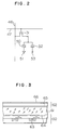
- the gate of a transistor is connected to a row electrode 47, the drain to a column electrode 46 and the source to a pixel electrode. Further, in Fig.
- a storage capacitor 52 in parallel with a capacitor of a pixel 50 of liquid crystal which is connected to a transparent pixel electrode 51 common to all the pixels.
- the other end of the storage capacitor 52 is connected to an electrode 53 exclusively used therefor to hold the storage capacitors for all the pixels at a same potential.
- This storage capacitor 52 is disposed for the purpose of preventing that the driving current of the liquid crystal is lowered in accordance with its proper leak current and therefore it is unnecessary, if the liquid crystal has a sufficiently high impedance.
- Fig. 3 is a cross-sectional view of the liquid crystal panel.
- a light-scattering type of liquid crystal 61 is put between two substrates 60 and 62.
- the lower substrate 60 is a single crystal wafer of silicon.
- transistors 63 are formed on the wafer transistors 63 are formed.
- the source electrode of each transistor is connected to a pixel electrode 64.
- This pixel electrode is made of metal such as aluminum, etc., which serves as a light reflecting layer.
- the substrate 62 opposite to the substrate 60 is made of transparent material such as glass, policarbonate, acrylate resin or the like, on the inner surface of which a transparent electrode 65 is disposed. Reflection by the transparent electrode 65 is prevented by controlling a thickness or the like of the electrode 65.
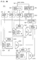
- Fig. 4A is a diagram showing the construction of the circuit integrated in the wafer, in which there are circuits 71, 72 and 73 for driving a display section 70 including pixels arranged in a matrix manner.
- Reference numeral 71 denotes a scanning side driving circuit for time-sequentially giving a gating voltage pulse to a group of row electrodes each connecting gates of the transistors, 72 a signal side driving circuit for time-sequentially giving a group of column electrodes a image signal, and 73 a control circuit for controlling both the driving circuits 71 and 72.
- Fig. 4B shows the circuit construction of the light valve.
- the light valve includes a liquid crystal display section 70, a horizontal scanning circuit 72-1, a sample circuit 72-2, a vertical scanning circuit 71-1 and an AND circuit group 71-2.
- Each of the pixels of the liquid crystal display section 70 includes a transistor 70a, a storage capacitor 70b and the liquid crystal capacitor 70c.
- the pixels are arranged in a matrix form of m rows and n columns to construct the liquid crystal display section.
- the horizontal and vertical scanning circuits 71-1 and 72-1, the sample circuit 72-2, and the AND circuit group 71-2 are for sequentially driving the display section 70 in units of pixels. These driving circuits are disposed on the monocrystal silicon constituting the display section 70.
- the circuit 72-1 inputs a start signal STA and a clock signal CLK from a circuit 73 and outputs sample signals PH1 to PHn.
- a switching circuit as the sample circuit 72-2 supplies alternated video signals VI1 and VI2 as drain signals Vd1 to Vdn to drains of the transistors in the display section 70 in synchronism with the sample signals PH1 to PHn.
- the circuit 71-1 inputs a start signal FST and a clock signal CKV and outputs vertical scanning signals PV1 to PVm.
- the AND circuit group 71-2 outputs gate signals VG1 to VGm in accordance with a control signal CNT and the signals PV1 to PVm to control scanning timing for the column or gate lines.
- Each of these circuits includes D type flip-flops FF 1 to FF p , inverters INV1 to INVp and level converting circuits LS1 to LSp.
- the p is n for the horizontal scanning circuit and m for the vertical scanning circuit.
- the flip-flops are connected in series to construct a shift register.
- a low voltage O-VDD (+5V) is supplied to the flip-flops FF and the inverters INV and a high voltage VSS(-15V) - VDD(+5V) is supplied to the level converting circuit LS.
- the start signal STA for the horizontal scanning circuit has, as a period, one horizontal scanning period.
- the sample signals PH1 to PHn are generated by catching the start signal STA at the rising timing of the clock signal CLK and by sequentially shifting the caught signal in the shift register, using the clock signal CLK.
- the start signal FST for the vertical scanning circuit has, as a period, a one-frame scanning period.
- the vertical scanning signals PV1 to PVm are generated by catching the start signal FST at the rising timing of the clock signal CKV and by sequentially shifting the caught signal in the shift register in synchronism with the signal CKV, similarly to the horizontal scanning circuit.
- the video signals VI1 and VI2 have a central voltage equal to a reference potential of the liquid crystal pixels 70b, the polarities thereof are opposite to each other and inverted for every horizontal scanning. These video signals are sampled at the timing of the sample signals from the horizontal scanning circuit and electric charge corresponding to the sampled signal is stored in the storage capacitor 70c.
- polymer-dispersed-type liquid crystal is used as the light-scattering-type liquid crystal and the operational characteristic thereof will be explained, referring to Figs. 5A and 5B.
- the polymer-dispersed-type liquid crystal panel includes a liquid crystal layer so constructed that nematic liquid crystal 82 is contained in an encapsulated manner in transparent organic material 81, e.g., polyvinyl alcohol. When no voltage is applied to a liquid crystal panel, nematic liquid crystal molecules are oriented parallel to the wall of the capsule, as shown in Fig. 5A.
- the liquid crystal molecules have an approximately elliptic cross-sectional construction, there are the liquid crystal molecules each having a minor or short axis of the ellipse with respect to incident light in a vertical direction from a up side to a down side of the figure with a high probability.
- a voltage is applied thereto from a driving voltage source 83, since the liquid crystal molecules are oriented so that the major or long axis thereof is directed in the direction of an electric field due to the applied voltage, as shown in Fig. 5B, the incident light is income into the liquid crystal molecules in the major axis direction thereof and thus transmitted.
- a part of the liquid crystal layer is transparent for pixels, under an electric field of sufficient intensity operated by transistors.
- Incident light to the liquid crystal panel in a downward direction passes through the liquid crystal layer and is reflected almost completely (in practice about 80 to 90%) by the reflecting layer serving as the pixel electrode.
- the reflecting layer serving as the pixel electrode.
- the incident light is scattered strongly within the liquid crystal layer, so that scattered light doesn't reach the screen, resulting in dark display of a part of the image corresponding to the pixels.
- intermediate tone display can be made through voltage modulation.
- the polarizing plate which was inevitable for the TN-type liquid crystal, can be omitted by using the light-scattering-type liquid crystal, and the brightness can be approximately double compared to the case of the TN-type liquid crystal.
- the pixel electrodes can be disposed on the transistors and the wiring electrodes, resulting in increasing the efficiency of light utilization. Consequently it is possible to realize a bright display with a lamp of a low electric power consumption, compared to a conventional projection-type display apparatus.
- the color-separating optical system and the color-combining optical system can be used in common, resulting in down sizing being possible.
- the peripheral driving circuit is integrated on the silicon monocrystal wafer, the number of connecting points with the exterior can be significantly reduced and remarkable effects can be obtained on improvement of the reliability and simplification of mounting, thereby resulting in the down sizing of the apparatus.
- the light-scattering-type liquid crystal is similar to that described in the first embodiment in that nematic liquid crystal 92 is enclosed by organic material 91.
- the nematic liquid crystal is not encapsulated (in an approximately spherical shape), but filled in gaps of the organic material, as shown in Fig. 6A.
- an optical behavior of the liquid crystal under the presence or absence of the electric field is identical to that described in the first embodiment, as apparent from Figs. 6A and 6B, since many parts of the liquid crystal connect to both the electrodes in the direction of electric field, the driving voltage can be lower than that required for the encapsulated polymer-dispersed-type liquid crystal.
- a liquid crystal material taking the smectic A phase is used as the light-scattering-type liquid crystal.
- the smectic A phase liquid crystal takes an orientation state called a focal conic structure in which light is scattered.
- the liquid crystal takes a homeotropic structure 102, in which the major axes of molecules of the liquid crystal are arranged properly in the direction of the electric field and thus the liquid crystal is in a transparent state. In this way the same display as described above can be achieved.
- only liquid crystal material is sealed between the electrodes and the panel can be fabricated by a method almost identical to that used for a conventional apparatus using TN-type liquid crystal.
- a switching circuit 111 for selecting and outputting one of two inputs is provided, for every pixel and formed of a plurality of transistors of each of the pixels.
- This switching circuit 111 reads out display information inputted from the column electrode 113 in response to a pulse voltage signal from the row electrode 112 and selects either one of the display voltages V(on) or V(off) to drive a pixel 114 of the liquid crystal.
- the circuit is constructed so as to hold the display information once read out, until the succeeding pulse voltage arrives, since V(on) or V(off) is always applied to the pixel 114 of the liquid crystal panel, there is no period of time when the circuit is in an opened state which is peculiar to the conventional example, viewed from the liquid crystal panel, and impedance control for the liquid crystal panel can be alleviated. Further, an effect of making the storage capacitor 115 unnecessary can be obtained.
- each of the pixels has a sample hold circuit S/H and an analogue amplifier Amp.
- the circuit S/H reads out analogue image information from the column electrode 122 in response to a pulse voltage from the row electrode 121 to hold the same.
- the analogue amplifier Amp is in charge of amplifying this analogue image information upto a predetermined level to drive a liquid crystal pixel.
- the liquid crystal pixel 123 is always driven by a voltage source of low impedance similarly to the third modified example and therefore it is possible to alleviate the impedance control for the liquid crystal panel and further to make the storage capacitor 124 unnecessary.
- a fifth modified example of the liquid crystal panel will be explained, referring to Fig. 9.
- the display driving section 131 and the peripheral circuit 132 but also a control circuit 134 including a frame memory 133 for storing display information for one screen and a controller for the frame memory are integrated in the silicon mono-crystal wafer.
- an external apparatus e.g., personal computer is required only, to write display information in the frame memory 133 and is not required to generate control timing signals and to perform high speed transfer of the display information in a time sequence manner.
- Figs. 11A and 11B show an example of the method for mounting the liquid crystal panel in the present embodiment.
- wiring terminals to the exterior are disposed previously on the dichroic prism 141 serving as the color separating/combining optical system and electric connection with the silicon monocrystal wafer 142 is effected through solder bumps or a silver paste or the like which is obtained by dispersing conductive particles into a material having adhesive property, as shown in Fig. 11B, i.e., on the basis of the chip-on-glass method.
- a liquid crystal layer 143 is located between the prism 141 and the wafer 142, that an opposite electrode 144 is disposed either on the liquid crystal or on the transparent glass and that connection from the prism 141 to the external circuit through the solder bumps is effected by means of a flexible flat cable 145.
- a sixth modified example of the liquid crystal panel will explained, referring to Fig. 10.
- a glass substrate 151 of the liquid crystal panel on the incident light side is inclined with respect to the optical axis.
- light components which are reflected by the surface of the glass substrate 151 and which would originally lowers the display quality are deviated from the optical axis so that they cannot arrive at the screen. Therefore worsening of the display quality can be prevented.
- light passing through the liquid crystal layer 152 in the transparent state and reflected by the surface of the silicon monocrystal wafer propagates along the predetermined optical axis and hence the display operation is not hindered.
- a first modified example of the first embodiment of the present invention will be explained referring to Fig. 12.
- a half mirror 161 is used instead of the reflecting mirror, white light emitted from a light source 162 is transformed to approximately parallel light by a lens 163. Approximately 50% of this parallel light is reflected by the half mirror 161 to the left of the figure and income to a dichroic prism 164 serving as the color separating/combining optical system.
- the operations of the dichroic prism and liquid crystal panels 165-R, 165-G and 165-B are identical to those described in the first embodiment. Light components reflected by the liquid crystal panels are combined and income again in the half mirror 161.
- the present optical system has an optical loss, the optical system can be simplified and a remarkable effect of down sizing of the apparatus and lowering in the price can be obtained.
- Figs. 13C and 13D are a diagrams showing the constructions of the pixels on the panels for odd and even scan lines obtained by the division, respectively.
- the screen 171 is so constructed that a number of pixels 172 are arranged in a two-dimensional matrix form.
- the screen 171 has scan lines from Line No. 1 to 2N.
- the scan lines are divided into two groups of the odd scan lines and the even scan lines. That is, the panel for odd scan line is constructed by only the pixels on the odd number scan lines among the pixels constituting the screen 171.
- the scan line numbers are 1, 3, 5, ---, 2N-1.
- the panel for even scan lines is constructed by only the pixels on the even number scan lines.
- the scan line numbers are 2, 4, ---, 2N.
- Each of the pixels on the liquid crystal panels obtained by division occupies an area twice as large as the area occupied before the division.
- circuit elements such as transistors, etc. are formed on the portion where a pixel is removed by the division.
- a transistor portion 175 is formed at the intersection of a scan line electrode wiring 173 and a signal electrode wiring 174.
- a pixel electrode 176 made of a material or the like having high reflectivity such as aluminum is disposed so as to cover a pattern of the transistor portion 175 and parts of the patterns of the scan line electrode 173 and the signal electrode 174 (in the figures this situation is shown in a clairvoyant state so that the positional relation of the transistor portion 175, etc. is clearly seen).
- a flat portion 177 of the pixel electrode corresponds to each pixel on each of the odd scan lines of the screen before the division (upper half in the figure) and the transistor portion 175 or the like is arranged in a part corresponding to pixels on each of the even scan lines before the division.
- a transistor portion 180 is formed at the intersection of a scan line electrode wiring 178 and a signal electrode wiring 179.
- the transistor portion 180 and a flat portion 182 for each pixel in the even scan lines are arranged in reverse to the case in the odd scan lines.
- the flat portion can always be obtained in the respective pixel electrode portions by dividing the scan lines of the screen into the odd and even scan lines and the area thereof is approximately equal to that of the each pixel of the screen before the division. For this reason light can be satisfactorily reflected and thus it is possible to realize a liquid crystal projector having a high efficiency of light utilization.
- FIG. 13A A display apparatus capable of projecting a color image on a screen, using the two panels for odd and even scan lines will be explained, referring to Fig. 13A.
- the fundamental construction of this display apparatus is identical to that of the display apparatus shown in Fig. 12. Therefore the identical constituent parts are indicated by same reference numerals and explanation thereof will be omitted.
- liquid crystal panels 165-B', 165-G' and 165-R' and a dichroic prism 164' are disposed on the transmission side of the half mirror 161.
- the arrangement of the liquid crystal panels 165-B', 165-G' and 165-R' and the dichroic prism 164' is identical to that of the display apparatus shown in Fig. 12.
- an image obtained from the liquid crystal panels 165-B' is inversed in the left and right sides, compared to that obtained from the liquid crystal panel 165-B. This can be achieved by scanning horizontally the liquid crystal panel 165-B' from the right side to the left side, when the liquid crystal panel 165-B is scanned horizontally from the left side to the right side.
- Fig. 14 shows a projection-type liquid crystal display apparatus, in which a section for realizing a lamp position adjusting function is integrated.
- the constituent parts identical to those shown in Fig. 1 are shown by same reference numerals.
- the lamp position adjustment in exchanging the lamp 11 serving as a light source is effected automatically.
- the lamp 11 Since it is thought that the lamp 11 is the exchange part having the shortest life in the present optical system, the exchange thereof is inevitable. Since this exchange is accompanied by usually complicated position adjusting work it was necessary that it is effected by a specialist.
- the present modified example is provided with a position fine-adjusting mechanism 1702 for adjusting finely the position of the lamp, a driving circuit 1703 for driving the mechanism 1702, a light detecting section 1704, a light detecting section moving mechanism 1705 and a light detecting section driving circuit 1706.
- a light focusing point is located at a point P within the optical system. It is sufficient to adjust the position of the lamp in exchanging it so that the light focusing point is positioned accurately at this point P. For this reason, the system is so constructed that the light detecting section 1704 can be positioned at the point P. Consequently the moving mechanism, which moves the light detecting section 1704 located usually at a position where the section 1704 doesn't obstruct the optical path, to the point P in exchanging the lamp, and the driving circuit 1706 therefor are driven.
- the section 1704 includes a light detecting element smaller than the light focusing spot at the point P. When the light amount detected by this light detecting element is highest, this means that light is focused just at this point P. At this time a light detection output is sent to the driving circuit 1703 for driving the adjusting mechanism 1702 to adjust finely the position of the lamp.
- the optical system since displacement of the photodetector is determined unambiguously, if the optical system is determined, it can be moved manually.
- the present photodetector can also be used for adjusting the optical axis, etc.
- the adjusting mechanism 1702 capable of being moved one-, two- or three-dimensionally can be used.
- a reflecting-type liquid crystal display apparatus has been described, it is a matter of course that in a transmitting-type liquid crystal display apparatus.
- the lamp position adjusting photodetector according to the present invention can also be used, if the light focusing point is disposed within the apparatus, so that lamp exchange or readjustment of a misaligned optical axis can be easily effected.
- lamp exchange can be effected easily according to the modified example described above, it is suitable for use at a place, where there is no specialist, such as domestic use.
- Fig. 15 shows the second embodiment of the present invention and the projection-type display apparatus according to the present embodiment is composed of three liquid crystal light valves 201, 204, 207, three CRTs 202, 205, 208 acting as plane light sources, a dichroic prism 210, a projection lens 211, and a control system 213. It includes further a screen 212 as an attached installation.
- the liquid crystal light valves 201, 204 and 207 for red, green and blue are controlled in accordance with image signals for red, green and blue images, which are supplied by the control system 213, to intensity-modulated red light 203, green light 206 and blue light 209 emitted by the fluorescent surfaces of the CRTs 202, 205 and 208 for red, green and blue which are disposed sufficiently closely to the liquid crystal light valves 201, 204 and 207, in order to generate red, green and blue images, respectively.
- the red light 203 and the blue light 209 thus intensity-modulated are reflected by interference films 210a and 210b of the dichroic prism 210 and income into a projection lens 211.
- the intensity-modulated green light 206 passes through the dichroic prism 210 and is income into the projection lens 211.
- three-colored light of the red light 203, the green light 206 and the blue light 209 is combined or synthesized and projected to the screen 212 by the projection lens 211 so that a color image is displayed on the screen 212.
- the liquid crystal light valves 201, 204 and 207 and the CRTs 202, 205 and 208 are arranged sufficiently closely to each other, respectively.
- the interference film 301 for red is attached to the tube surface of the CRT 202 for red
- the interference film 302 for green is attached to the tube surface of the CRT 205 for green
- the interference film 303 for blue is attached to the tube surface of the CRT 208 for blue.
- the efficiency of the light utilization is high and it is possible to reproduce easily a sufficiently bright color image.
- dispersed-type liquid crystal light valves in which thin film transistors (TFT) are incorporated, are used for the liquid crystal light valves 201, 204 and 207 modulating the different colors. Therefore the construction and the principle of the dispersed-type liquid crystal light valve will be explained, referring to Figs. 16A and 16B.
- a dispersed-type liquid crystal light valve is so constructed that a liquid crystal layer 223 including a number of liquid crystal grains 223a is sandwiched between a transparent substrate 220a having a transparent electrode 221a and that a transparent substrate 220b having similarly a transparent electrode 221b, which is opposite to the former, and a signal source 224 and a switch 225 are connected between these transparent electrodes 221a and 221b. Since the many liquid crystal grains 223a are oriented at random, when the switch 225 is turned-off so that no electric field is generated in the liquid crystal layer 223, light income into the liquid crystal layer 223 at this time is scattered, as shown in the figure and therefore the liquid crystal light valve holds its opaque state.
- the switch 225 when the switch 225 is turned-on and the electric field by the signal source is generated in the liquid crystal layer 223 between the transparent electrodes and when the voltage corresponding to this electric field exceeds a certain voltage V 1 , all the liquid crystal molecules in each of the liquid crystal grains within the liquid crystal layer 223 are aligned in the direction of the electric field. In this way the incident light passes therethrough and thus the liquid crystal light valve becomes transparent. That is, this dispersed-type liquid crystal light valve is switched-over between the opaque state and the transparent state, depending on the presence or absence of the signal voltage, and thus performs a light valve function. Further, when the applied voltage is controlled at values lower than V 1 , the degree of the scattering can be controlled. As the result, the light valve can also display intermediate tones by using a voltage signal modulated by the image signal as the signal source 224 and thus act as an image reproducing device.
- this dispersed-type liquid crystal light valve requires no polarizing plate, it has a high efficiency of light utilization. Further, in the present embodiment as described previously, an interference film for red 301 is stuck or laminated on the tube surface of the CRT for red 202; an interference film for green 302 is stuck on the tube surface of the CRT for green 205; and an interference film for blue 303 is stuck on the tube surface of the CRT for blue 208. As the result, a collimator lens effect is given to the front glass part of each of the CRT. Therefore, no generated light is uselessly dispersed, which increases remarkably the efficiency.
- a fluorescent plane 231 is disposed on the inner surface of the face plate (light emitting plate) 230 of the CRT and the interference film 232 is stuck on the surface opposite to the fluorescent plane 231, when the fluorescent plane 231 is irradiated with an electron beam 233, the fluorescent plane 231 emits fluorescence at specified wavelengths.
- the fluorescent plane 231 In the case of the CRT for red, light is emitted principally in a red wavelength region and in the case of the CRT for green, light is emitted principally in a green wavelength region.
- the interference film 232 is composed of a multi-layered evaporation film of a dielectric substance having a refractive index different from that of glass material constituting the face plate 230 and it can have an incident angle dependency concerning its transmission characteristics for light having a predetermined wavelength.
- the light valve can be so constructed that light 234 emitted perpendicularly to the fluorescent plane 231 is almost transmitted without any loss by the interference film 232, but light 235 emitted by the fluorescent plane 231 in a certain direction forming an angle ⁇ with the direction perpendicular to the surface thereof is reflected by the interference film 232.
- Fig. 17B shows the relation between the angle ⁇ and the light amount transmitted via the interference film 232 at this time.
- Light emitted over a wide angular region is transformed by the interference film 232 into light spread only over a narrow angular region. Consequently light is income into each of the liquid crystal light valves 201, 204 and 207.
- emission intensity for different colors can be controlled independently from each other by controlling electron beam current for each of the CRTs 202, 205 and 208, it is possible to effect color adjustment extremely easily.
- twisted-nematic-type liquid crystal light valves or supertwisted-nematic-type liquid crystal light valve can be used as well instead thereof.
- the shown positional relation between the different colors is only an example and it can be modified arbitrarily. It is a matter of cause that it is possible to combine light by using a combination of dichroic mirrors instead of a dichroic prism, too.
- An image signal 314 received from broadcast electromagnetic wave or inputted from a video deck, a video disk or another arbitrary signal source is at first supplied to a color demodulating circuit 315 to be converted there into different color signals of red, green and blue, which correspond to the three primary colors.
- the color signals obtained by this conversion are stored in frame memories 317, 318 and 319 for every frame in the form of digital data, respectively.
- the image signal 314 is also inputted to a sync signal separating circuit 316 by which a reference sync signal component for the different signals is separated therefrom, and a sync signal is generated by a sync signal reproducing circuit 320.
- Red image signal data is inputted from a frame memory 317 controlled by the reproducing circuit 320 to a signal circuit 323 for controlling the liquid crystal light valve for red 201.
- the light valve 201 is controlled there by the signal circuit 323 and a scanning circuit 324 to reproduce a red image.
- the sync signal generated by the reproducing circuit 320 is converted into horizontal and vertical scanning signals by a synchronization control circuit 321 and in addition supplied to a CRT for red 202 disposed, adjacent to the light valve 201, through a beam control circuit 322 to control light emission in a raster form in synchronism with reproduction of the red image from the liquid crystal light valve 201 so as to drive it as a red plane light source.
- liquid crystal light valves 204 and 207 for green and blue are controlled by signal circuits 327 and 325 as well as scanning circuits 328 and 326 to reproduce a green image and a blue image and at the same time light emission by CRTs 205 and 208 for green and blue is controlled in synchronism with reproduction of the green image and the blue image from the liquid crystal light valves 204 and 207 for green and blue, respectively.
- each of the CRTs 202, 205 and 208 in the present embodiment is effected by scanning the fluorescent plane in a raster scan form with an electron beam. Consequently a light emitting point on the CRT corresponding to a pixel on each of the liquid crystal light valves 201, 204 and 207 emits light only once during one frame.
- a liquid crystal light valve using TFTs is scanned by the line sequential scanning method and pixel information is held, until it is selected to be updated. Consequently, in an image reproducing apparatus using usual CRTs, a light emitting portion on the fluorescent plane thereof represents image information itself.
- the CRTs used in the present embodiment are used only as light sources. Increase in the total brightness is realized by increasing the current intensity of the electron beam to increase the area emitting light for every scanning and this will be explained around the light emitting state of the CRT, referring to Figs. 19A to 19D.
- Fig. 19A enlargingly shows a part of the pixels of the liquid crystal light valve.
- the electron beam of the CRT corresponding thereto is swept from the left to the right and downward in the order of a, b and c.
- the pixel pitch P is about, e.g., 64 ⁇ m for a liquid crystal light valve having a size of 2 in. measured along a diagonal.
- the current intensity of the electron beam of the CRT is increased so that the diameter of the electron beam is about 120 ⁇ m, which is twice as large as the pixel pitch.
- the light emitting portion on the fluorescent plane of the CRT is enlarged so that pixels on a plurality of lines are irradiated simultaneously at each instant.
- Such a liquid crystal light valve by the TFT driving method is fabricated at a relatively high cost because of a low yield at present. Therefore a modified example of the second embodiment, by which the number of used liquid crystal light valves is reduced so that increase in the cost is suppressed and that further down sizing is made possible, will be explained below.
- Fig. 20 shows the construction of the present modified example.
- the liquid crystal light valve used in the second embodiment described previously is disposed before none of the CRTs, but a single liquid crystal light valve is disposed between the dichroic prism 210 and the projection lens 211.
- the constituent parts identical to those in the second embodiment are denoted by same reference numerals and explanation thereof will be omitted.
- Red light 203 and blue light 209 produced by the CRTs for red and blue 202 and 208 are reflected by reflecting films for red and blue 210a and 210b and green light 206 produced by the CRT for green 205 passes through the dichroic prism 210.
- Light from the prism 210 is income into the projection lens 211 after having been intensity-modulated by the liquid crystal light valve 401.
- Light of the three primary colors emitted by the three CRTs 202, 205 and 208 is intensity-modulated by the single liquid crystal light valve 401 so as to display a color image on the screen by means of the projection lens 211.
- the dichroic prims 210 is located between the different CRTs 202, 205 and 208 and the liquid crystal light valve 401. Therefore it is important that the light produced by the different CRTs is income into the projection lens with a high efficiency. Also in the present modified example an interference film is stuck or laminated on the tube surface of each of the CRTs so that light emitted by each of the CRTs is income into the projection lens with a high efficiency, as explained referring to Fig. 3.
- control system 213' the three CRTs 202, 205 and 208 as well as the liquid crystal light valve 401 are controlled by a control system 213'.
- This control system 213' will be explained, referring to Fig. 21.
- An image signal 314 received from broadcast electromagnetic wave, or inputted from a video deck, a video disk or another arbitrary signal source is supplied at first to a color demodulating circuit 315 to be converted there into different color signals of red, green and blue, which are the three primary colors.
- the color signals obtained by this conversion are stored in frame memories 317, 318 and 319 for every frame in the form of digital data, respectively.
- the image signal 314 is also inputted to a separating circuit 316, by which a reference sync signal component for the different signals is separated therefrom and a sync signal is reproduced by a reproducing circuit 357.
- the frequency of the sync signal generated by the reproducing circuit 357 is so determined to be three times as high as that of the sync signal of the image signal 314.
- red, green and blue image signal data are inputted from frame memories 317, 318 and 319 respectively, controlled by the reproducing circuit 357, to the signal circuit 360 controlling the liquid crystal light valve 401.
- the liquid crystal light valve 401 is controlled by the signal circuit 360 and the scanning circuit 361 to reproduce red, green and blue images.
- the sync signal generated by the reproducing circuit 357 is converted into horizontal and vertical scanning signals by a synchronization control circuit 358 and in addition supplied to the CRTs 202, 205 and 208 so as to control these CRTs in synchronism with reproduction of a red, a green and a blue image on the liquid crystal light valve 401.
- Figs. 22A to 22D show the reproduced image on the liquid crystal light valve 401, the fluorescent state of the CRT for red 202, the fluorescent state of the CRT for green 205 and the fluorescent state of the CRT for blue 208, respectively, arranged time-sequentially, as shown downward by 1 to 6. After 6 the process returns to 1. Consequently, in the present modified example, the color reproduction by a so-called "frame sequential method", by which the images of different colors of red, green and blue are displayed time-sequentially during one frame period.
- the single liquid crystal light valve 401 reproducing or generating the images of different colors corresponding to the three primary colors by the frame sequential method and the three CRTs 202, 205 and 208 emitting the different colors corresponding to the three primary colors are controlled successively in synchronism with each other so that the color image is projected on the screen 212 and that an enlarged image is reproduced.
- Fig. 23A shows one frame period of a usual image signal.
- One frame period of the scanning signal applied to the liquid crystal light valve 401 is 1/90 sec, which is equal to 1/3 of one frame period (1/30 sec) of a usual image signal (e.g., video signal).
- the image signal of a red image is applied to this liquid crystal light valve 401.
- a green image signal and then a blue image signal are applied thereto.
- the transmissivity of a certain pixel on the liquid crystal light valve 401 varies, depending on the image signal applied thereto. That is, as shown by Fig. 23B, for example, the transmissivity has a value corresponding to the red image by the red image signal for the first frame, a value corresponding to the green image by the green image signal for the second frame, and a value corresponding to the blue image by the blue image signal. Further, although it is not shown in the figure, for the succeeding frame the transmissivity has a value corresponding again to the red image of the succeeding image.
- the CRT for red 202 is scanned with the electron beam in synchronism with the red image signal supplied to the liquid crystal light valve 401 to emit light as shown in Fig. 23C.
- the CRT for green 205 is scanned with the electron beam in synchronism with the green image signal applied to the liquid crystal light valve 401 to emit light as shown in Fig. 23D.
- the CRT for blue 208 is scanned with the electron beam in synchronism with the blue image signal applied to the liquid crystal light valve 401 to emit light as shown in Fig. 23E. Consequently, according to the present modified example, one liquid crystal light valve is sufficient and it is possible to realize a projection-type color display apparatus having a smaller size at a low cost.
- Fig. 24 shows a cross-sectional construction of the tube surface of each of the CRTs, in which a lens surface 512 is formed on the tube surface of the CRT, which is opposite to the fluorescent plane 231.
- Light 434 emitted by irradiating the electron beam 233 into the fluorescent plane 231 is not dispersed owing to this lens surface 512, as shown in the figure.
- This lens surface 512 forms a so-called lenticular lens, in which a plurality of small lenses are arranged in an array shape, and the focal point of each of the lenses is located so as to be in accordance with the fluorescent plane 231 described previously.
- This lens surface 512 may be formed either by processing the tube surface 230 in a lens shape or by fabricating a separate lens array in a sheet shape, which is pasted or stuck on the tube surface 230. According to this modified example, the processing cost can be low and thus it is possible to obtain a lower cost projection-type display apparatus.
Landscapes
- Engineering & Computer Science (AREA)
- Multimedia (AREA)
- Signal Processing (AREA)
- Physics & Mathematics (AREA)
- Nonlinear Science (AREA)
- General Physics & Mathematics (AREA)
- Optics & Photonics (AREA)
- Liquid Crystal (AREA)
- Liquid Crystal Display Device Control (AREA)
- Devices For Indicating Variable Information By Combining Individual Elements (AREA)
Applications Claiming Priority (7)
| Application Number | Priority Date | Filing Date | Title |
|---|---|---|---|
| JP7822791A JPH04291292A (ja) | 1991-03-19 | 1991-03-19 | 投射型カラー表示装置 |
| JP78227/91 | 1991-03-19 | ||
| JP7822791 | 1991-03-19 | ||
| JP8812391 | 1991-04-19 | ||
| JP88123/91 | 1991-04-19 | ||
| JP08812391A JP3168598B2 (ja) | 1991-04-19 | 1991-04-19 | 液晶表示装置を用いた投射型液晶ディスプレイ装置 |
| EP92104602A EP0504813B1 (de) | 1991-03-19 | 1992-03-17 | Verfahren zur Projektion eines durch Anwendung von Flüssigkristallanzeigen erhaltenen Bildes und Anzeigevorrichtung zur Durchführung des Verfahrens |
Related Parent Applications (2)
| Application Number | Title | Priority Date | Filing Date |
|---|---|---|---|
| EP92104602.5 Division | 1992-03-17 | ||
| EP92104602A Division EP0504813B1 (de) | 1991-03-19 | 1992-03-17 | Verfahren zur Projektion eines durch Anwendung von Flüssigkristallanzeigen erhaltenen Bildes und Anzeigevorrichtung zur Durchführung des Verfahrens |
Publications (2)
| Publication Number | Publication Date |
|---|---|
| EP0808071A1 true EP0808071A1 (de) | 1997-11-19 |
| EP0808071B1 EP0808071B1 (de) | 2000-12-06 |
Family
ID=26419314
Family Applications (2)
| Application Number | Title | Priority Date | Filing Date |
|---|---|---|---|
| EP97111311A Expired - Lifetime EP0808071B1 (de) | 1991-03-19 | 1992-03-17 | Flüssigkristallanzeigevorrichtung |
| EP92104602A Expired - Lifetime EP0504813B1 (de) | 1991-03-19 | 1992-03-17 | Verfahren zur Projektion eines durch Anwendung von Flüssigkristallanzeigen erhaltenen Bildes und Anzeigevorrichtung zur Durchführung des Verfahrens |
Family Applications After (1)
| Application Number | Title | Priority Date | Filing Date |
|---|---|---|---|
| EP92104602A Expired - Lifetime EP0504813B1 (de) | 1991-03-19 | 1992-03-17 | Verfahren zur Projektion eines durch Anwendung von Flüssigkristallanzeigen erhaltenen Bildes und Anzeigevorrichtung zur Durchführung des Verfahrens |
Country Status (5)
| Country | Link |
|---|---|
| US (3) | US5404175A (de) |
| EP (2) | EP0808071B1 (de) |
| KR (1) | KR100246248B1 (de) |
| CN (1) | CN1036874C (de) |
| DE (2) | DE69224540T2 (de) |
Cited By (1)
| Publication number | Priority date | Publication date | Assignee | Title |
|---|---|---|---|---|
| US6882379B1 (en) | 1998-06-05 | 2005-04-19 | Seiko Epson Corporation | Light source device including a planar light source having a single, substantially continuous light emission area and display device incorporating the light source device |
Families Citing this family (42)
| Publication number | Priority date | Publication date | Assignee | Title |
|---|---|---|---|---|
| US7115902B1 (en) | 1990-11-20 | 2006-10-03 | Semiconductor Energy Laboratory Co., Ltd. | Electro-optical device and method for manufacturing the same |
| KR950013784B1 (ko) | 1990-11-20 | 1995-11-16 | 가부시키가이샤 한도오따이 에네루기 겐큐쇼 | 반도체 전계효과 트랜지스터 및 그 제조방법과 박막트랜지스터 |
| US5849601A (en) * | 1990-12-25 | 1998-12-15 | Semiconductor Energy Laboratory Co., Ltd. | Electro-optical device and method for manufacturing the same |
| US7098479B1 (en) | 1990-12-25 | 2006-08-29 | Semiconductor Energy Laboratory Co., Ltd. | Electro-optical device and method for manufacturing the same |
| US7576360B2 (en) * | 1990-12-25 | 2009-08-18 | Semiconductor Energy Laboratory Co., Ltd. | Electro-optical device which comprises thin film transistors and method for manufacturing the same |
| EP0808071B1 (de) * | 1991-03-19 | 2000-12-06 | Hitachi, Ltd. | Flüssigkristallanzeigevorrichtung |
| US5461501A (en) * | 1992-10-08 | 1995-10-24 | Hitachi, Ltd. | Liquid crystal substrate having 3 metal layers with slits offset to block light from reaching the substrate |
| US7081938B1 (en) * | 1993-12-03 | 2006-07-25 | Semiconductor Energy Laboratory Co., Ltd. | Electro-optical device and method for manufacturing the same |
| US6232947B1 (en) | 1994-03-15 | 2001-05-15 | Canon Kabushiki Kaisha | Video information display system including a reflective type active matrix addressed liquid crystal display and method for synthetically combining and editing data |
| JP3402400B2 (ja) * | 1994-04-22 | 2003-05-06 | 株式会社半導体エネルギー研究所 | 半導体集積回路の作製方法 |
| US6943764B1 (en) | 1994-04-22 | 2005-09-13 | Semiconductor Energy Laboratory Co., Ltd. | Driver circuit for an active matrix display device |
| US5555035A (en) * | 1994-10-03 | 1996-09-10 | Hughes Aircraft Company | Very high resolution light valve writing system based on tilting lower resolution flat panels |
| US5795047A (en) * | 1994-12-09 | 1998-08-18 | Matsushita Electric Industrial Co., Ltd. | Projection lens and projection display apparatus |
| JPH08220657A (ja) * | 1994-12-15 | 1996-08-30 | Nikon Corp | 投射装置 |
| JP3631296B2 (ja) * | 1995-04-04 | 2005-03-23 | 三菱電機株式会社 | 画像生成装置 |
| JP3520131B2 (ja) * | 1995-05-15 | 2004-04-19 | 株式会社東芝 | 液晶表示装置 |
| CN1074221C (zh) * | 1995-08-21 | 2001-10-31 | 明碁电脑股份有限公司 | 一种影像扫描装置 |
| JPH09114397A (ja) * | 1995-10-19 | 1997-05-02 | Mitsubishi Electric Corp | ディスプレイデバイスおよびディスプレイ装置 |
| US5743612A (en) * | 1995-11-10 | 1998-04-28 | Hitachi, Ltd | Liquid crystal projector |
| JP3735158B2 (ja) * | 1996-06-06 | 2006-01-18 | オリンパス株式会社 | 画像投影システム、画像処理装置 |
| US6243152B1 (en) * | 1996-12-17 | 2001-06-05 | Duke University | Contrast polymer dispersed liquid crystal projection display system |
| JP3900663B2 (ja) * | 1997-06-25 | 2007-04-04 | ソニー株式会社 | 光学空間変調素子及び画像表示装置 |
| JP3228896B2 (ja) * | 1997-10-24 | 2001-11-12 | キヤノン株式会社 | 反射型lcdパネルユニット及びこれを用いた液晶プロジェクター |
| JPH11249011A (ja) * | 1998-02-27 | 1999-09-17 | Minolta Co Ltd | プロジェクター光学系 |
| JPH11282378A (ja) * | 1998-03-26 | 1999-10-15 | Sony Corp | カラープロジェクタ |
| US6512502B2 (en) * | 1998-05-27 | 2003-01-28 | International Business Machines Corporation | Lightvalve projection system in which red, green, and blue image subpixels are projected from two lightvalves and recombined using total reflection prisms |
| US6467911B1 (en) * | 1998-10-08 | 2002-10-22 | Minolta Co., Ltd. | Projector and lamp unit |
| JP2000347177A (ja) * | 1999-03-29 | 2000-12-15 | Minolta Co Ltd | 表示光学装置及びそれを用いたプロジェクター表示装置 |
| GB9917973D0 (en) | 1999-07-31 | 1999-09-29 | Thomson Training & Simulation | Image display apparatus |
| US6384890B1 (en) * | 1999-11-15 | 2002-05-07 | National Semiconductor Corporation | Connection assembly for reflective liquid crystal projection with branched PCB display |
| WO2001057838A1 (en) * | 2000-01-31 | 2001-08-09 | Seiko Epson Corporation | Electrooptic device and driving method thereof |
| US6690432B2 (en) * | 2001-04-12 | 2004-02-10 | Koninklijke Philips Electronics N.V. | Alignment of the optical and the electrical scan in a scrolling color projector |
| US6927471B2 (en) | 2001-09-07 | 2005-08-09 | Peter C. Salmon | Electronic system modules and method of fabrication |
| US7297572B2 (en) * | 2001-09-07 | 2007-11-20 | Hynix Semiconductor, Inc. | Fabrication method for electronic system modules |
| JP4111074B2 (ja) * | 2002-08-20 | 2008-07-02 | セイコーエプソン株式会社 | プロジェクタ |
| US6940097B2 (en) | 2003-08-19 | 2005-09-06 | Hewlett-Packard Development Company, L.P. | Optical property normalization for a transparent electrical device |
| KR100616556B1 (ko) * | 2004-06-12 | 2006-08-28 | 김은수 | 무손실 편광형 입체 디스플레이방법 및 장치 |
| US7327408B1 (en) * | 2004-11-15 | 2008-02-05 | Lightmaster Systems, Inc. | Illuminator that generates linearly polarized light for microdisplay based light engine |
| US7059523B1 (en) * | 2005-04-28 | 2006-06-13 | Symbol Technologies, Inc. | Scan line alignment in raster pattern |
| JP5935679B2 (ja) * | 2012-04-02 | 2016-06-15 | ソニー株式会社 | 照明装置および表示装置 |
| CN109507843B (zh) * | 2017-09-14 | 2022-01-21 | 扬明光学股份有限公司 | 合光模组 |
| CN111190323B (zh) * | 2018-11-15 | 2022-05-13 | 中兴通讯股份有限公司 | 一种投影器和终端 |
Citations (9)
| Publication number | Priority date | Publication date | Assignee | Title |
|---|---|---|---|---|
| US3862360A (en) * | 1973-04-18 | 1975-01-21 | Hughes Aircraft Co | Liquid crystal display system with integrated signal storage circuitry |
| US4239346A (en) * | 1979-05-23 | 1980-12-16 | Hughes Aircraft Company | Compact liquid crystal display system |
| JPS6126027A (ja) * | 1984-07-17 | 1986-02-05 | Seiko Epson Corp | 液晶表示パネル駆動回路 |
| US4745485A (en) * | 1985-01-28 | 1988-05-17 | Sanyo Electric Co., Ltd | Picture display device |
| WO1988007250A2 (en) * | 1987-03-16 | 1988-09-22 | The Cherry Corporation | Video display interface |
| EP0294899A2 (de) * | 1987-06-10 | 1988-12-14 | Koninklijke Philips Electronics N.V. | Anzeigevorrichtung für den reflektierenden Betrieb |
| EP0342925A2 (de) * | 1988-05-17 | 1989-11-23 | Seiko Epson Corporation | Anzeigetafel mit aktiver Matrix |
| WO1991002372A1 (en) * | 1989-08-11 | 1991-02-21 | Raf Electronics Corp. | Wafer based active matrix |
| WO1991003003A1 (en) * | 1989-08-11 | 1991-03-07 | Raf Electronics Corp. | An active matrix reflective projection system |
Family Cites Families (35)
| Publication number | Priority date | Publication date | Assignee | Title |
|---|---|---|---|---|
| FR639807A (fr) * | 1927-07-30 | 1928-06-30 | Dispositif applicable aux gills de tous genres en vue de préparer pour la filature les rubans formés de fibres très longues ou sans fin | |
| GB402137A (en) * | 1932-05-27 | 1933-11-27 | Aage Christensen | Improvements in rotary furnaces for combustion of town refuse and the like |
| US4127322A (en) * | 1975-12-05 | 1978-11-28 | Hughes Aircraft Company | High brightness full color image light valve projection system |
| US4295159A (en) * | 1980-06-05 | 1981-10-13 | General Electric Company | Light projection system |
| US4703344A (en) * | 1985-03-30 | 1987-10-27 | Omron Tateisi Electronics Co. | Illumination system of the digital control type |
| US4836649A (en) * | 1985-07-12 | 1989-06-06 | Hughes Aircraft Company | Optical layout for a three light valve full-color projector employing a dual relay lens system and a single projection lens |
| GB2191057A (en) * | 1986-05-19 | 1987-12-02 | Philips Electronic Associated | Colour video display arrangement |
| JPH0792561B2 (ja) * | 1986-07-08 | 1995-10-09 | 株式会社精工舎 | 投写式液晶表示装置 |
| NL8701347A (nl) * | 1987-06-10 | 1989-01-02 | Philips Nv | Vloeibaar kristal weergeefinrichting en werkwijze ter vervaardiging van een dergelijke weergeefinrichting. |
| US4842374A (en) * | 1987-07-27 | 1989-06-27 | Hughes Aircraft Company | Unitary prepolarizing prism assembly for a four color liquid crystal light valve image projector |
| JP2620791B2 (ja) * | 1987-10-16 | 1997-06-18 | セイコー電子工業株式会社 | 光学像書き込み投影装置 |
| JPH01195782A (ja) * | 1988-01-29 | 1989-08-07 | Victor Co Of Japan Ltd | 液晶表示装置 |
| US4943154A (en) * | 1988-02-25 | 1990-07-24 | Matsushita Electric Industrial Co., Ltd. | Projection display apparatus |
| GB8807090D0 (en) * | 1988-03-24 | 1988-04-27 | Secr Defence | Liquid crystal colour display |
| JPH0212291A (ja) * | 1988-06-30 | 1990-01-17 | Sony Corp | 投射型画像表示装置 |
| DE3829598A1 (de) * | 1988-08-29 | 1990-03-01 | Hertz Inst Heinrich | Projektionsgeraet |
| US5150232A (en) * | 1988-10-04 | 1992-09-22 | Asahi Glass Company Ltd. | Active matrix liquid crystal display element and projection type active matrix liquid crystal display device |
| GB2226174A (en) * | 1988-12-14 | 1990-06-20 | Philips Electronic Associated | Liquid crystal display devices |
| JPH02212291A (ja) * | 1989-02-10 | 1990-08-23 | Mitsubishi Heavy Ind Ltd | プロペラ翼の翼間間隔制御方法 |
| JPH02293716A (ja) * | 1989-05-08 | 1990-12-04 | Matsushita Electric Ind Co Ltd | 三板式投射型液晶ディスプレイ装置 |
| US5424780C1 (en) * | 1989-05-22 | 2002-07-23 | James C Cooper | Apparatus and method for special scan modulation of a video display |
| JPH032429A (ja) * | 1989-05-30 | 1991-01-08 | Mitsubishi Heavy Ind Ltd | 建設機械の自動運行装置 |
| JPH0744688B2 (ja) * | 1989-06-08 | 1995-05-15 | 三菱電機株式会社 | 投写型テレビジヨン装置 |
| JPH0311390A (ja) * | 1989-06-08 | 1991-01-18 | Matsushita Electric Ind Co Ltd | 投写型画像表示装置 |
| US5260815A (en) * | 1989-08-03 | 1993-11-09 | Nippon Hoso Kyokai | Light writing type projection display using polymer-dispersed liquid crystal and liquid crystal television set as image light source |
| DE69023217T2 (de) * | 1989-08-03 | 1996-07-18 | Japan Broadcasting Corp | Projektionssichtgerät mit optischem schreiben. |
| EP0415396B1 (de) * | 1989-08-31 | 1997-03-05 | Asahi Glass Company Ltd. | Flüssigkristallfarbprojektionsanzeigevorrichtung |
| NL8902205A (nl) * | 1989-09-01 | 1991-04-02 | Philips Nv | Projektiesysteem. |
| JP2714995B2 (ja) * | 1990-05-29 | 1998-02-16 | 三菱電機株式会社 | 投写型陰極線管 |
| US5095377A (en) * | 1990-08-02 | 1992-03-10 | Matsushita Electric Industrial Co., Ltd. | Method of driving a ferroelectric liquid crystal matrix panel |
| DE69132253T2 (de) * | 1990-11-28 | 2001-01-04 | Canon K.K., Tokio/Tokyo | Lichtstreuende Flüssigkristallvorrichtung |
| JP3119709B2 (ja) * | 1990-12-20 | 2000-12-25 | 旭硝子株式会社 | 液晶表示装置及び投射型液晶表示装置 |
| US5170250A (en) * | 1991-02-06 | 1992-12-08 | Hughes Aircraft Company | Full-color light valve projection apparatus having internal image registration system |
| EP0808071B1 (de) * | 1991-03-19 | 2000-12-06 | Hitachi, Ltd. | Flüssigkristallanzeigevorrichtung |
| JP3719452B2 (ja) * | 1995-10-17 | 2005-11-24 | 同和鉱業株式会社 | 単結晶銅の製造方法 |
-
1992
- 1992-03-17 EP EP97111311A patent/EP0808071B1/de not_active Expired - Lifetime
- 1992-03-17 DE DE69224540T patent/DE69224540T2/de not_active Expired - Fee Related
- 1992-03-17 EP EP92104602A patent/EP0504813B1/de not_active Expired - Lifetime
- 1992-03-17 DE DE69231597T patent/DE69231597T2/de not_active Expired - Fee Related
- 1992-03-18 KR KR1019920004418A patent/KR100246248B1/ko not_active Expired - Fee Related
- 1992-03-18 US US07/853,426 patent/US5404175A/en not_active Expired - Lifetime
- 1992-03-19 CN CN92101838A patent/CN1036874C/zh not_active Expired - Fee Related
-
1995
- 1995-03-30 US US08/413,428 patent/US5614962A/en not_active Expired - Lifetime
-
1997
- 1997-02-27 US US08/805,665 patent/US5875006A/en not_active Expired - Lifetime
Patent Citations (9)
| Publication number | Priority date | Publication date | Assignee | Title |
|---|---|---|---|---|
| US3862360A (en) * | 1973-04-18 | 1975-01-21 | Hughes Aircraft Co | Liquid crystal display system with integrated signal storage circuitry |
| US4239346A (en) * | 1979-05-23 | 1980-12-16 | Hughes Aircraft Company | Compact liquid crystal display system |
| JPS6126027A (ja) * | 1984-07-17 | 1986-02-05 | Seiko Epson Corp | 液晶表示パネル駆動回路 |
| US4745485A (en) * | 1985-01-28 | 1988-05-17 | Sanyo Electric Co., Ltd | Picture display device |
| WO1988007250A2 (en) * | 1987-03-16 | 1988-09-22 | The Cherry Corporation | Video display interface |
| EP0294899A2 (de) * | 1987-06-10 | 1988-12-14 | Koninklijke Philips Electronics N.V. | Anzeigevorrichtung für den reflektierenden Betrieb |
| EP0342925A2 (de) * | 1988-05-17 | 1989-11-23 | Seiko Epson Corporation | Anzeigetafel mit aktiver Matrix |
| WO1991002372A1 (en) * | 1989-08-11 | 1991-02-21 | Raf Electronics Corp. | Wafer based active matrix |
| WO1991003003A1 (en) * | 1989-08-11 | 1991-03-07 | Raf Electronics Corp. | An active matrix reflective projection system |
Non-Patent Citations (1)
| Title |
|---|
| PATENT ABSTRACTS OF JAPAN vol. 10, no. 177 (P - 470) 21 June 1986 (1986-06-21) * |
Cited By (3)
| Publication number | Priority date | Publication date | Assignee | Title |
|---|---|---|---|---|
| US6882379B1 (en) | 1998-06-05 | 2005-04-19 | Seiko Epson Corporation | Light source device including a planar light source having a single, substantially continuous light emission area and display device incorporating the light source device |
| US7126652B2 (en) | 1998-06-05 | 2006-10-24 | Seiko Epson Corporation | Light source device including a planar light source having a single, substantially continuous light emission area and display device incorporating the light source device |
| EP1003062B1 (de) * | 1998-06-05 | 2006-11-08 | Seiko Epson Corporation | Lichtquelle und anzeigevorrichtung |
Also Published As
| Publication number | Publication date |
|---|---|
| EP0504813A3 (en) | 1993-12-08 |
| EP0808071B1 (de) | 2000-12-06 |
| DE69231597T2 (de) | 2001-05-31 |
| CN1036874C (zh) | 1997-12-31 |
| EP0504813B1 (de) | 1998-03-04 |
| US5404175A (en) | 1995-04-04 |
| DE69224540D1 (de) | 1998-04-09 |
| KR100246248B1 (ko) | 2000-03-15 |
| DE69231597D1 (de) | 2001-01-11 |
| DE69224540T2 (de) | 1998-06-25 |
| EP0504813A2 (de) | 1992-09-23 |
| US5875006A (en) | 1999-02-23 |
| US5614962A (en) | 1997-03-25 |
| KR920018507A (ko) | 1992-10-22 |
| CN1064952A (zh) | 1992-09-30 |
Similar Documents
| Publication | Publication Date | Title |
|---|---|---|
| EP0808071B1 (de) | Flüssigkristallanzeigevorrichtung | |
| JP3308880B2 (ja) | 液晶表示装置と投写型液晶表示装置 | |
| US5108172A (en) | Active matrix reflective image plane module and projection system | |
| US4850685A (en) | Projection-type color display device | |
| KR100325924B1 (ko) | 매트릭스기판,이매트릭스기판을사용하는액정장치및이액정장치를사용하는표시장치 | |
| US5075798A (en) | Projection-type display device | |
| JPH04507008A (ja) | アクティブマトリックス反射型投写装置 | |
| US5357288A (en) | Liquid crystal projector and method of projecting image | |
| JP2714939B2 (ja) | 投写型カラー表示装置 | |
| US5241407A (en) | Projection-type display device | |
| US7106389B2 (en) | Optical shifter and projection type optical display system | |
| JPS61150487A (ja) | 液晶ビデオ・プロジエクタ | |
| JP3278270B2 (ja) | 彩色表示装置 | |
| JPS603291A (ja) | 投写式液晶表示装置 | |
| JP3877012B2 (ja) | 単色光電子管カラー映写装置 | |
| JP3337022B2 (ja) | プロジェクタ | |
| JP3118281B2 (ja) | 小型ディスプレイ装置 | |
| USRE36725E (en) | Projection-type display device | |
| JPS61183688A (ja) | 投写型液晶表示装置 | |
| JP2746267B2 (ja) | 投写型カラー表示装置の製造方法 | |
| JPH09265106A (ja) | 液晶ディスプレイパネルおよび投射型液晶表示装置 | |
| JPH0772498A (ja) | 複数画像合成投影装置 | |
| JPH04291292A (ja) | 投射型カラー表示装置 | |
| JP2682207B2 (ja) | 表示装置 | |
| JPH04289837A (ja) | 投射型表示装置 |
Legal Events
| Date | Code | Title | Description |
|---|---|---|---|
| PUAI | Public reference made under article 153(3) epc to a published international application that has entered the european phase |
Free format text: ORIGINAL CODE: 0009012 |
|
| AC | Divisional application: reference to earlier application |
Ref document number: 504813 Country of ref document: EP |
|
| AK | Designated contracting states |
Kind code of ref document: A1 Designated state(s): CH DE FR GB LI |
|
| 17P | Request for examination filed |
Effective date: 19970926 |
|
| RIN1 | Information on inventor provided before grant (corrected) |
Inventor name: FUKUDA, KYOHEI Inventor name: HOSHINO, MINORU Inventor name: SATO, HIDEO Inventor name: MIKAMI, YOSHIRO Inventor name: MORI, YUJI Inventor name: NAGAE, YOSHIHARU |
|
| 17Q | First examination report despatched |
Effective date: 19990520 |
|
| GRAG | Despatch of communication of intention to grant |
Free format text: ORIGINAL CODE: EPIDOS AGRA |
|
| GRAG | Despatch of communication of intention to grant |
Free format text: ORIGINAL CODE: EPIDOS AGRA |
|
| RTI1 | Title (correction) |
Free format text: LIQUID CRYSTAL DISPLAY APPARATUS |
|
| 17Q | First examination report despatched |
Effective date: 19990520 |
|
| GRAG | Despatch of communication of intention to grant |
Free format text: ORIGINAL CODE: EPIDOS AGRA |
|
| GRAH | Despatch of communication of intention to grant a patent |
Free format text: ORIGINAL CODE: EPIDOS IGRA |
|
| GRAH | Despatch of communication of intention to grant a patent |
Free format text: ORIGINAL CODE: EPIDOS IGRA |
|
| GRAA | (expected) grant |
Free format text: ORIGINAL CODE: 0009210 |
|
| AC | Divisional application: reference to earlier application |
Ref document number: 504813 Country of ref document: EP |
|
| AK | Designated contracting states |
Kind code of ref document: B1 Designated state(s): CH DE FR GB LI |
|
| REG | Reference to a national code |
Ref country code: CH Ref legal event code: NV Representative=s name: TROESCH SCHEIDEGGER WERNER AG Ref country code: CH Ref legal event code: EP |
|
| REF | Corresponds to: |
Ref document number: 69231597 Country of ref document: DE Date of ref document: 20010111 |
|
| ET | Fr: translation filed | ||
| PLBE | No opposition filed within time limit |
Free format text: ORIGINAL CODE: 0009261 |
|
| STAA | Information on the status of an ep patent application or granted ep patent |
Free format text: STATUS: NO OPPOSITION FILED WITHIN TIME LIMIT |
|
| 26N | No opposition filed | ||
| REG | Reference to a national code |
Ref country code: GB Ref legal event code: IF02 |
|
| PGFP | Annual fee paid to national office [announced via postgrant information from national office to epo] |
Ref country code: FR Payment date: 20030117 Year of fee payment: 12 |
|
| PGFP | Annual fee paid to national office [announced via postgrant information from national office to epo] |
Ref country code: GB Payment date: 20030307 Year of fee payment: 12 |
|
| PGFP | Annual fee paid to national office [announced via postgrant information from national office to epo] |
Ref country code: CH Payment date: 20030528 Year of fee payment: 12 |
|
| PGFP | Annual fee paid to national office [announced via postgrant information from national office to epo] |
Ref country code: DE Payment date: 20030530 Year of fee payment: 12 |
|
| PG25 | Lapsed in a contracting state [announced via postgrant information from national office to epo] |
Ref country code: GB Free format text: LAPSE BECAUSE OF NON-PAYMENT OF DUE FEES Effective date: 20040317 |
|
| PG25 | Lapsed in a contracting state [announced via postgrant information from national office to epo] |
Ref country code: LI Free format text: LAPSE BECAUSE OF NON-PAYMENT OF DUE FEES Effective date: 20040331 Ref country code: CH Free format text: LAPSE BECAUSE OF NON-PAYMENT OF DUE FEES Effective date: 20040331 |
|
| PG25 | Lapsed in a contracting state [announced via postgrant information from national office to epo] |
Ref country code: DE Free format text: LAPSE BECAUSE OF NON-PAYMENT OF DUE FEES Effective date: 20041001 |
|
| GBPC | Gb: european patent ceased through non-payment of renewal fee |
Effective date: 20040317 |
|
| REG | Reference to a national code |
Ref country code: CH Ref legal event code: PL |
|
| PG25 | Lapsed in a contracting state [announced via postgrant information from national office to epo] |
Ref country code: FR Free format text: LAPSE BECAUSE OF NON-PAYMENT OF DUE FEES Effective date: 20041130 |
|
| REG | Reference to a national code |
Ref country code: FR Ref legal event code: ST |