EP0807939B1 - Bobine supraconductrice - Google Patents
Bobine supraconductrice Download PDFInfo
- Publication number
- EP0807939B1 EP0807939B1 EP97107591A EP97107591A EP0807939B1 EP 0807939 B1 EP0807939 B1 EP 0807939B1 EP 97107591 A EP97107591 A EP 97107591A EP 97107591 A EP97107591 A EP 97107591A EP 0807939 B1 EP0807939 B1 EP 0807939B1
- Authority
- EP
- European Patent Office
- Prior art keywords
- superconducting
- coil
- coils
- wire
- accordance
- Prior art date
- Legal status (The legal status is an assumption and is not a legal conclusion. Google has not performed a legal analysis and makes no representation as to the accuracy of the status listed.)
- Expired - Lifetime
Links
Images


Classifications
-
- H—ELECTRICITY
- H01—ELECTRIC ELEMENTS
- H01F—MAGNETS; INDUCTANCES; TRANSFORMERS; SELECTION OF MATERIALS FOR THEIR MAGNETIC PROPERTIES
- H01F6/00—Superconducting magnets; Superconducting coils
- H01F6/06—Coils, e.g. winding, insulating, terminating or casing arrangements therefor
-
- H—ELECTRICITY
- H01—ELECTRIC ELEMENTS
- H01R—ELECTRICALLY-CONDUCTIVE CONNECTIONS; STRUCTURAL ASSOCIATIONS OF A PLURALITY OF MUTUALLY-INSULATED ELECTRICAL CONNECTING ELEMENTS; COUPLING DEVICES; CURRENT COLLECTORS
- H01R4/00—Electrically-conductive connections between two or more conductive members in direct contact, i.e. touching one another; Means for effecting or maintaining such contact; Electrically-conductive connections having two or more spaced connecting locations for conductors and using contact members penetrating insulation
- H01R4/58—Electrically-conductive connections between two or more conductive members in direct contact, i.e. touching one another; Means for effecting or maintaining such contact; Electrically-conductive connections having two or more spaced connecting locations for conductors and using contact members penetrating insulation characterised by the form or material of the contacting members
- H01R4/68—Connections to or between superconductive connectors
-
- Y—GENERAL TAGGING OF NEW TECHNOLOGICAL DEVELOPMENTS; GENERAL TAGGING OF CROSS-SECTIONAL TECHNOLOGIES SPANNING OVER SEVERAL SECTIONS OF THE IPC; TECHNICAL SUBJECTS COVERED BY FORMER USPC CROSS-REFERENCE ART COLLECTIONS [XRACs] AND DIGESTS
- Y10—TECHNICAL SUBJECTS COVERED BY FORMER USPC
- Y10S—TECHNICAL SUBJECTS COVERED BY FORMER USPC CROSS-REFERENCE ART COLLECTIONS [XRACs] AND DIGESTS
- Y10S505/00—Superconductor technology: apparatus, material, process
- Y10S505/70—High TC, above 30 k, superconducting device, article, or structured stock
- Y10S505/704—Wire, fiber, or cable
- Y10S505/705—Magnetic coil
-
- Y—GENERAL TAGGING OF NEW TECHNOLOGICAL DEVELOPMENTS; GENERAL TAGGING OF CROSS-SECTIONAL TECHNOLOGIES SPANNING OVER SEVERAL SECTIONS OF THE IPC; TECHNICAL SUBJECTS COVERED BY FORMER USPC CROSS-REFERENCE ART COLLECTIONS [XRACs] AND DIGESTS
- Y10—TECHNICAL SUBJECTS COVERED BY FORMER USPC
- Y10S—TECHNICAL SUBJECTS COVERED BY FORMER USPC CROSS-REFERENCE ART COLLECTIONS [XRACs] AND DIGESTS
- Y10S505/00—Superconductor technology: apparatus, material, process
- Y10S505/70—High TC, above 30 k, superconducting device, article, or structured stock
- Y10S505/706—Contact pads or leads bonded to superconductor
-
- Y—GENERAL TAGGING OF NEW TECHNOLOGICAL DEVELOPMENTS; GENERAL TAGGING OF CROSS-SECTIONAL TECHNOLOGIES SPANNING OVER SEVERAL SECTIONS OF THE IPC; TECHNICAL SUBJECTS COVERED BY FORMER USPC CROSS-REFERENCE ART COLLECTIONS [XRACs] AND DIGESTS
- Y10—TECHNICAL SUBJECTS COVERED BY FORMER USPC
- Y10S—TECHNICAL SUBJECTS COVERED BY FORMER USPC CROSS-REFERENCE ART COLLECTIONS [XRACs] AND DIGESTS
- Y10S505/00—Superconductor technology: apparatus, material, process
- Y10S505/825—Apparatus per se, device per se, or process of making or operating same
- Y10S505/879—Magnet or electromagnet
-
- Y—GENERAL TAGGING OF NEW TECHNOLOGICAL DEVELOPMENTS; GENERAL TAGGING OF CROSS-SECTIONAL TECHNOLOGIES SPANNING OVER SEVERAL SECTIONS OF THE IPC; TECHNICAL SUBJECTS COVERED BY FORMER USPC CROSS-REFERENCE ART COLLECTIONS [XRACs] AND DIGESTS
- Y10—TECHNICAL SUBJECTS COVERED BY FORMER USPC
- Y10S—TECHNICAL SUBJECTS COVERED BY FORMER USPC CROSS-REFERENCE ART COLLECTIONS [XRACs] AND DIGESTS
- Y10S505/00—Superconductor technology: apparatus, material, process
- Y10S505/825—Apparatus per se, device per se, or process of making or operating same
- Y10S505/884—Conductor
- Y10S505/887—Conductor structure
Definitions
- the present invention relates to a superconducting coil, and more particularly, it relates to a superconducting coil for a superconducting magnet which is applied to a magnetic resonance diagnostic apparatus or the like and cooled by a cryogenic refrigerator, for example.
- superconducting magnets are cooled by two types of methods including a method of dipping and cooling a superconducting magnet in a refrigerant such as liquid helium or liquid nitrogen, and a method of thermally connecting a superconducting magnet directly to a cold head of a cryogenic refrigerator.
- a refrigerant such as liquid helium or liquid nitrogen
- a superconducting conductor is generally wound on a coil former (bobbin) in the form of a pancake or solenoid.
- Japanese Patent Laying-Open No. 6-174349 (1994) proposes means of interposing a mixture of silicon grease and a powder material having excellent thermal conductivity in a connecting portion between the cryogenic refrigerator and the superconducting magnet while filling up clearances between coil wires and those between the coil and the bobbin with the mixture, in order to improve the cooling efficiency for the superconducting magnet having such a structure.
- EP-A-0 556 837 discloses methods of joining superconducting wires using oxide high-temperature superconductor.
- the superconducting wires consist of multifilament wires.
- the filaments are brought into contact by superposing and joined with each other by a heat treatment.
- another oxide superconducting member is interposed between the filaments for joining the same by a heat treatment. In both methods a heat treatment of the superconducting material forming the wires is necessary.
- the present invention relates to a superconducting coil comprising a plurality of coils, each of said coils being formed by superconducting conductors, said coils being connected by a connecting part.
- connection conductors of adjacent pancake-shaped superconducting coils are soldered with each other and connected with a bind wire.
- the connection conductors are lifted through an insulating material away from other coil conductors. Thereby, cooling effect is improved along with a higher mechanical strength of the connecting part.
- the superconducting coil having the aforementioned structure is employed for a superconducting magnet which is cooled by a cryogenic refrigerator.
- grease containing a ceramic additive in a silicon oil solvent is filled up in a clearance between the first and second coil wires and the interiors of the first and second coil wires.
- the ceramic additive is prepared from at least one of SiO 2 , Al 2 O 3 , AlN and ZnO.
- the first and second coil wires are in the form of pancake coils.
- each of the first and second superconducting conductors is formed by stacking first and second superconducting wires having tape-like shapes with each other.
- the superconducting filaments preferably consist of an oxide superconductor.
- the oxide superconductor is preferably prepared from a bismuth superconductor. Further, the bismuth superconductor preferably contains either a 2223 phase or a 2212 phase.
- the first superconducting conductor may include a first superconducting wire which is relatively outwardly arranged in the first coil and a second superconducting wire which is relatively inwardly arranged in the first coil
- the second superconducting conductor may include a first superconducting wire which is relatively outwardly arranged in the second coil and a second superconducting wire which is relatively inwardly arranged in the second coil.
- the first superconducting wire relatively outwardly arranged in the first coil is joined with the first superconducting wire relatively outwardly arranged in the second coil and the second superconducting wire relatively inwardly arranged in the first coil is joined with the second superconductor relatively inwardly arranged in the second coil.
- the first superconducting conductor may include a first superconducting wire which is relatively outwardly arranged in the first coil and a second superconducting wire which is relatively inwardly arranged in the first coil
- the second superconducting conductor may include a first superconducting wire which is relatively inwardly arranged in the second coil and a second superconducting wire which is relatively outwardly arranged in the second coil in the superconducting coil having the aforementioned structure.
- the first superconducting wire relatively outwardly arranged in the first coil is joined with the first superconducting wire relatively inwardly arranged in the second coil
- the second superconducting wire relatively inwardly arranged in the first coil is joined with the second superconducting wire relatively outwardly arranged in the second coil.
- temperature rise of the superconducting coil can be suppressed to enable a stable operation even if the coil is excited at a high speed, whereby a superconducting magnet can be continuously driven with employment of the structure of the inventive superconducting coil.
- the superconducting coil according to the present invention When the superconducting coil according to the present invention is applied to a superconducting magnet which is cooled by a cryogenic refrigerator, a more preferable effect can be attained. Further, cooling efficiency to a prescribed very low temperature can be improved by filling up a clearance between the coil wires and the interiors thereof with grease containing a ceramic additive in a silicon oil solvent.
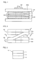
- Fig. 1 schematically illustrates the structure of a superconducting magnet employing a superconducting coil according to an embodiment of the present invention.
- a superconducting coil 100 is mounted on a bobbin 200.
- the superconducting coil 100 is formed by a plurality of double pancake coils such as three double pancake superconducting coils 110, 120 and 130, for example. Clearances between the superconducting coils 110, 120 and 130, those between the superconducting coils 110 and 130 and the bobbin 200, and the interiors of the superconducting coils 110, 120 and 130 are coated or impregnated with grease 400 of a silicon oil solvent containing ceramic grains of ZnO or the like having excellent thermal conductivity.
- a cold head 300 of a cryogenic refrigerator is thermally connected directly to a flange 200a of the bobbin 200.
- Superconducting conductors are wound on the bobbin 200 to form the superconducting coils 110, 120 and 130, which are connected with each other.
- Fig. 2 is a side elevational view schematically showing the connection structure between two double pancake superconducting coils 101 and 102.
- the double pancake superconducting coil 101 is formed by first and second coil parts 101a and 101b consisting of oppositely wound superconducting conductors.
- the double pancake superconducting coil 102 is also formed by first and second coil parts 102a and 102b consisting of oppositely wound superconducting conductors.
- the double pancake superconducting coils 101 and 102 are connected with each other on a connecting part 150.
- Fig. 3 is a sectional view showing a superconducting conductor 10 forming each of the superconducting coils 101 and 102.
- the superconducting conductor 10 is formed by a plurality of tape-like superconducting multifilamentary wires such as three tape-like superconducting multifilamentary wires 11, 12 and 13, for example.
- the tape-like superconducting multifilamentary wires 11, 12 and 13 are stacked with each other to form the superconducting conductor 10, and relatively outwardly positioned in this order in each of the superconducting coils 101 and 102.
- Fig. 4 shows a section of a single tape-like superconducting multifilamentary wire 1. As shown in Fig. 4, a number of superconducting filaments 2 consisting of an oxide superconductor are embedded in a stabilizer 3 consisting of silver or the like in the tape-like superconducting multifilamentary wire 1.
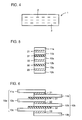
- Figs. 5 and 6 are sectional views of the connecting part 150 taken along the lines A - A and B - B in Fig. 2 respectively.
- a superconducting conductor 10b extends from the second coil part 101b of the superconducting coil 101 shown in Fig. 2 toward the first coil part 102a of the superconducting coil 102.
- a superconducting conductor 10a extends from the first coil part 102a of the superconducting coil 102 shown in Fig. 2 toward the second coil part 101b of the superconducting coil 101.
- the superconducting conductor 10a is formed by three tape-like superconducting multifilamentary wires 11a, 12a and 13a which are stacked with each other.
- the superconducting conductor 10b is also formed by three tape-like superconducting multifilamentary wires 11b, 12b and 13b which are stacked with each other.
- the tape-like superconducting multifilamentary wire 11a is electrically connected with the tape-like superconducting multifilamentary wire 11b by a solder layer (Pb-Sn alloy) 21.
- a solder layer Pb-Sn alloy
- the tape-like superconducting multifilamentary wire 12a is electrically connected with the tape-like superconducting multifilamentary wire 12b by a solder layer 22.
- the tape-like superconducting multifilamentary wire 13a is electrically connected with the tape-like superconducting multifilamentary wire 13b by a solder layer 23.
- Insulating materials 31 and 32 of polyimide or the like are interposed between the joint bodies.
- the clearances between the superconducting coils 110, 120 and 130, those between the superconducting coils 110 and 130 and the bobbin 200, and the interiors of the superconducting coils 110, 120 and 130 are filled up with the grease 400 of a silicon oil solvent containing ceramic powder having excellent thermal conductivity, as shown in Fig. 1.
- the superconducting coils 110, 120 and 130 can be effectively cooled by filling up the clearances requiring thermal conduction with the grease 400.
- the superconducting coils 110, 120 and 130 can be rapidly cooled to a prescribed very low temperature in case of cooling the superconducting magnet by thermally connecting the same directly to the cold head 300 of the cryogenic refrigerator.
- the superconducting magnet can be efficiently initially cooled to the prescribed very low temperature by employing the aforementioned inventive connection structure between the superconducting coils 110, 120 and 130 and filling up the clearances and the interiors with the prescribed grease 400, while the superconducting magnet can be continuously driven in a state maintained at a prescribed low temperature after cooling.
- FIGs. 8 and 9 are sectional views of the connecting part 150 shown in Fig. 2 taken along the lines A - A and B - B respectively.
- the conventional connection structure is described with reference to these figures.
- a superconducting conductor 10a is formed by three tape-like superconducting multifilamentary wires 11a, 12a and 13a.
- Another superconducting conductor 10b is also formed by three tape-like superconducting multifilamentary wires 11b, 12b and 13b.
- the tape-like superconducting multifilamentary wires 11a, 12a and 13a and 11b, 12b and 13b are not separated from each other but stacked and collectively connected with each other to form the superconducting conductors 10a and 10b respectively.
- the superconducting conductor 10a formed by the three tape-like superconducting multifilamentary wires 11a, 12a and 13a is electrically connected with the superconducting conductor 10b formed by the three tape-like superconducting multifilamentary wires 11b, 12b and 13b in the stacked state through a solder layer 20 entirely covering the same.
- the inventor considers that the connection resistance between the superconducting conductors 10a and 10b disperses depending on the method of forming the solder layer 20 in the aforementioned conventional connection structure.
- the inventor also considers that an excessive current flows to parts of the tape-like superconducting multifilamentary wires 11a, 12a, 13a, 11b, 12b and 13b to generate a voltage and heat.
- the inventor further considers that normal conducting transition consequently results in the superconducting coil.
- connection structure according to the present invention has been attained as a result of various studies on connection structures between superconducting coils, to enable suppression of heat generation in the superconducting coil due to the aforementioned structure.
- Fig. 10 conceptually illustrates a mode of connection between superconducting coils according to another embodiment of the present invention.
- superconducting conductors 50a and 50b extend from first and second superconducting coils respectively.
- the superconducting conductor 50a is formed by five stacked tape-like superconducting multifilamentary wires 51a, 52a, 53a, 54a and 55a, which are relatively outwardly positioned in this order in the first superconducting coil.
- the superconducting conductor 50b is also formed by five stacked tape-like superconducting multifilamentary wires 51b, 52b, 53b, 54b and 55b, which are relatively outwardly positioned in this order in the second superconducting coil.
- the tape-like superconducting multifilamentary wire 51a is electrically connected with the tape-like superconducting multifilamentary wire 55b, as shown at 61.
- the tape-like superconducting multifilamentary wire 52a is electrically connected with the tape-like superconducting multifilamentary wire 54b, as shown at 62.
- the tape-like superconducting multifilamentary wire 53a is electrically connected with the tape-like superconducting multifilamentary wire 53b, as shown at 63.
- the tape-like superconducting multifilamentary wire 54a is electrically connected with the tape-like superconducting multifilamentary wire 52b, as shown at 64.
- the tape-like superconducting multifilamentary wire 55a is electrically connected with the tape-like superconducting multifilamentary wire 51b, as shown at 65.
- the superconducting multifilamentary wires forming the superconducting conductor 50a and being relatively outwardly positioned in the coil are successively electrically connected with the superconducting multifilamentary wires forming the superconducting conductor 50b and being relatively inwardly positioned in the coil.
- the superconducting multifilamentary wires can be uniformalized in inductance in the superconducting coils. Consequently, heat generation of the superconducting coils can be further effectively suppressed so that loss can be reduced in excitation with an alternating current.
- the present invention is also applicable to superconducting conductors having shapes other than the tape-like ones.
- the superconducting filaments are made of an oxide superconductor such as a bismuth oxide superconductor, for example, in each of the aforementioned embodiments, the present invention is applicable not only to superconducting filaments of an oxide superconductor but those made of a metal superconductor or the like.
- the tape-like superconducting multifilamentary wire 1 shown in Fig. 4 was prepared as follows:
- Oxides or carbonates of respective elements were mixed with each other so that Bi, Pb, Sr, Ca and Cu were in the ratios of 1.80:0.41:2.01:2.18:3.02, for preparing powder mainly consisting of a 2212 phase and a non-superconducting phase by heat treatment.
- This powder was degassed in the atmosphere at 800°C for two hours.
- the degassed powder was charged in a silver pipe of 12 mm in outer diameter and 10 mm in inner diameter, which in turn was drawn to a diameter of 1.93 mm.
- 61 such drawn pipes were charged in a silver pipe of 21.23 mm in outer diameter and 17.37 mm in inner diameter, which in turn was further drawn to an outer diameter of 1.4 mm.
- This wire was rolled to a thickness of 0.24 mm.
- the superconducting multifilamentary wire 1 prepared in the aforementioned manner exhibited a section shown in Fig. 4.
- 61 superconducting filaments 2 consisting of a bismuth oxide superconductor (mainly of a 2223 phase) are embedded in a stabilizer 3 consisting of silver, as shown in Fig. 4.
- the tape-like superconducting multifilamentary wire 1 had a thickness of 0.24 mm and a width of 3.6 mm.
- This superconducting conductor 10 was further wound on a bobbin 200, for forming double pancake superconducting coils.
- Fig. 1 shows three double pancake superconducting coils 110, 120 and 130, 19 double pancake superconducting coils were stacked and formed around a bobbin in this Example.
- the total height of the 19 double pancake superconducting coils was 150 mm, while the outer and inner diameters were 180 mm and 60 mm respectively.
- the total number of turns of the 19 stacked double pancake superconducting coils was 2600.
- the 19 double pancake superconducting coils were connected with each other in the structure shown in Figs. 2, 5 and 6.
- the thickness of each of the solder layers (Pb-Sn alloy) 21, 22 and 23 was 10 to 100 ⁇ m.
- the insulating materials 31 and 32 were prepared from polyimide. The thickness of each of the insulating materials 31 and 32 was about 15 ⁇ m.
- a superconducting magnet was formed by the superconducting coils prepared in the aforementioned manner. Further, a cold head of a cryogenic refrigerator was thermally connected directly to the superconducting magnet. Namely, a cold head 300 was thermally connected directly to a flange 200a of the bobbin 200, as shown in Fig. 1.
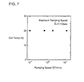
- the superconducting magnet was driven under conditions of a coil current of 100 A and a central magnetic field of 2 T.
- the employed cryogenic refrigerator had cooling ability capable of maintaining a low temperature of 20 K with respect to a heat generation capacitance of 4 W. In the superconducting magnet driven under such conditions, it was possible to cool the superconducting coils to a temperature of 20 K in about 20 hours.
- Fig. 7 shows the relation between the temperature (K) at the center of the superconducting coil and the respective ramping speeds (T/min.). The maximum ramping speed was 2 (T/10 sec.). It is understood from Fig. 7 that the temperature of the superconducting coil was substantially unchanged and maintained at 20 K despite increase of the ramping speeds.
Landscapes
- Engineering & Computer Science (AREA)
- Power Engineering (AREA)
- Physics & Mathematics (AREA)
- Condensed Matter Physics & Semiconductors (AREA)
- General Physics & Mathematics (AREA)
- Superconductors And Manufacturing Methods Therefor (AREA)
Claims (11)
- Bobine supraconductrice (100) comprenant une pluralité de bobines (101, 102 ; 110, 120, 130) ;chacune desdites bobines (101, 102 ; 110, 120, 130) étant formée par des conducteurs supraconducteurs (10 ; 10a, 10b) ;lesdites bobines (101, 102 ; 110, 120, 130) étant connectées par une pièce de connexion (150) ;grâce à quoi un premier conducteur supraconducteur (10a) s'étendant depuis une première bobine (102) est connecté à un deuxième conducteur supraconducteur (10b) s'étendant depuis une deuxième bobine (101) ;
caractérisée en ce quelesdits conducteurs supraconducteurs (10 ; 10a, 10b) sont formés d'une pluralité de fils à multifilaments supraconducteurs (11, 12, 13 ; 11a, 12a, 13a ; 11b, 12b, 13b), chacun desdits fils à multifilaments supraconducteurs comprenant des filaments supraconducteurs (2) ;lesdits premier et deuxième conducteurs supraconducteurs sont connectés de façon que chacun desdits fils à multifilaments (11a, 12a, 13a) dudit premier conducteur supraconducteur (10a) soit réuni par une connexion électrique effectuée par une couche de brasure (21, 22, 23) avec l'un desdits fils à multifilaments (11b, 12b, 13b) dudit deuxième conducteur supraconducteur (10b) ; etlesdites connexions électriques forment des corps de joint qui sont isolés mutuellement par un matériau isolant (31, 32) interposé entre les corps de joint. - Bobine supraconductrice selon la revendication 1, qui est appliquée à un aimant supraconducteur refroidi par un réfrigérateur cryogénique (300).
- Bobine supraconductrice selon la revendication 2, dans laquelle une graisse (400) contenant un additif céramique dans un solvant de type huile de silicone remplit un espace entre lesdites première et deuxième bobines et les intérieurs desdites première et deuxième bobines.
- Bobine supraconductrice selon la revendication 3, dans laquelle ledit additif céramique est au moins un matériau choisi dans le groupe constitué par SiO2, Al2O3, AlN et ZnO.
- Bobine supraconductrice selon la revendication 1, dans laquelle lesdites première et deuxième bobines sont des bobines plates.
- Bobine supraconductrice selon la revendication 1, dans laquelle chacun desdits conducteurs supraconducteurs (10) est formé par empilement d'une pluralité de fils supraconducteurs (11, 12, 13) ayant des formes de ruban.
- Bobine supraconductrice selon la revendication 1, dans laquelle lesdits filaments supraconducteurs (2) sont constitués d'un supraconducteur de type oxyde.
- Bobine supraconductrice selon la revendication 7, dans laquelle ledit supraconducteur de type oxyde est un supraconducteur au bismuth.
- Bobine supraconductrice selon la revendication 8, dans laquelle ledit supraconducteur au bismuth contient soit une phase 2223 soit une phase 2212.
- Bobine supraconductrice selon la revendication 1, dans laquelleledit premier conducteur supraconducteur (10a) comprend un premier fil supraconducteur (11a) qui est agencé relativement vers l'extérieur dans ladite première bobine (102), et un deuxième fil supraconducteur (13a) qui est agencé relativement vers l'intérieur dans ladite première bobine (102), etledit deuxième conducteur supraconducteur (10b) comprend un premier fil supraconducteur (11b) qui est agencé relativement vers l'extérieur dans ladite deuxième bobine (101), et un deuxième fil supraconducteur (13b) qui est agencé relativement vers l'intérieur dans ladite deuxième bobine (101).
- Bobine supraconductrice selon la revendication 1, dans laquelleledit premier conducteur supraconducteur (50a) comprend un premier fil supraconducteur (51a) qui est agencé relativement vers l'extérieur dans ladite première bobine, et un deuxième fil supraconducteur (55a) qui est agencé relativement vers l'intérieur dans ladite première bobine, etledit deuxième conducteur supraconducteur (50b) comprend un premier fil supraconducteur (55b) qui est agencé relativement vers l'intérieur dans ladite deuxième bobine, et un deuxième fil supraconducteur (51b) qui est agencé relativement vers l'extérieur dans ladite deuxième bobine.
Applications Claiming Priority (6)
| Application Number | Priority Date | Filing Date | Title |
|---|---|---|---|
| JP11791296 | 1996-05-13 | ||
| JP117912/96 | 1996-05-13 | ||
| JP11791296 | 1996-05-13 | ||
| JP9108958A JPH1041125A (ja) | 1996-05-13 | 1997-04-25 | 超電導コイル |
| JP108958/97 | 1997-04-25 | ||
| JP10895897 | 1997-04-25 |
Publications (2)
| Publication Number | Publication Date |
|---|---|
| EP0807939A1 EP0807939A1 (fr) | 1997-11-19 |
| EP0807939B1 true EP0807939B1 (fr) | 2001-10-17 |
Family
ID=26448773
Family Applications (1)
| Application Number | Title | Priority Date | Filing Date |
|---|---|---|---|
| EP97107591A Expired - Lifetime EP0807939B1 (fr) | 1996-05-13 | 1997-05-07 | Bobine supraconductrice |
Country Status (5)
| Country | Link |
|---|---|
| US (1) | US5861788A (fr) |
| EP (1) | EP0807939B1 (fr) |
| JP (1) | JPH1041125A (fr) |
| CA (1) | CA2204845A1 (fr) |
| DE (1) | DE69707349T2 (fr) |
Families Citing this family (12)
| Publication number | Priority date | Publication date | Assignee | Title |
|---|---|---|---|---|
| JP3521612B2 (ja) * | 1996-05-13 | 2004-04-19 | 住友電気工業株式会社 | 超電導導体の接続構造 |
| US6693504B1 (en) | 2000-01-11 | 2004-02-17 | American Superconductor Corporation | Internal support for superconductor windings |
| KR100720057B1 (ko) * | 2005-07-06 | 2007-05-18 | 학교법인 한국산업기술대학 | 영구전류용 초전도자석 및 제조방법 |
| FR2895802B1 (fr) * | 2005-12-30 | 2008-11-07 | Commissariat Energie Atomique | Procede et dispositif de creation d'un champ magnetique homogene dans une zone d'interet, notamment pour l'imagerie rmn |
| CN101236239B (zh) * | 2007-01-30 | 2012-01-25 | 西门子(中国)有限公司 | 磁共振系统的超导磁体的电流引线 |
| JP4881225B2 (ja) * | 2007-06-05 | 2012-02-22 | 住友重機械工業株式会社 | 超電導コイル及び超電導マグネット装置 |
| JP2011187524A (ja) * | 2010-03-05 | 2011-09-22 | Hitachi Ltd | 高温超電導並列導体、それを用いた高温超電導コイル及び高温超電導マグネット |
| US8729894B2 (en) * | 2010-07-30 | 2014-05-20 | General Electric Company | System and method for operating a magnetic resonance imaging system during ramping |
| DE102011107313A1 (de) | 2011-07-06 | 2013-01-10 | Karlsruher Institut für Technologie | Isolierter Hochtemperatur-Bandsupraleiter und Verfahren zu seiner Herstellung |
| JP6109532B2 (ja) * | 2012-11-06 | 2017-04-05 | 株式会社東芝 | 超電導コイル |
| WO2014192832A1 (fr) * | 2013-05-28 | 2014-12-04 | 株式会社フジクラ | Dispositif de connexion de tige d'enroulement, procédé de connexion de tige d'enroulement et procédé de fabrication d'une structure de connexion |
| JP6884681B2 (ja) * | 2017-11-14 | 2021-06-09 | 株式会社東芝 | 超電導線の接続部及びその接続方法、超電導磁石装置 |
Family Cites Families (16)
| Publication number | Priority date | Publication date | Assignee | Title |
|---|---|---|---|---|
| GB1104693A (en) * | 1964-02-25 | 1968-02-28 | Nat Res Dev | Improvements in or relating to the manufacture of superconducting solenoids |
| DE1665830A1 (de) * | 1966-12-16 | 1971-04-15 | Siemens Ag | Bandfoermiger,aus Supraleitermaterial und elektrisch normalleitendem Metall bestehender Leiter und Supraleitungsspule mit einer Wicklung aus diesem Leiter |
| JPS5648109A (en) * | 1979-09-28 | 1981-05-01 | Hitachi Ltd | Superconductive magnet |
| JPS6395607A (ja) * | 1986-10-09 | 1988-04-26 | Furukawa Electric Co Ltd:The | パンケ−キマグネツトコイルの接続方法 |
| JPH0748420B2 (ja) * | 1989-08-29 | 1995-05-24 | 三菱電機株式会社 | 超電導コイル装置 |
| JPH04155711A (ja) * | 1990-10-19 | 1992-05-28 | Central Res Inst Of Electric Power Ind | 高温超電導交流用線材及びその製造方法 |
| AU653983B2 (en) * | 1991-02-25 | 1994-10-20 | Sumitomo Electric Industries, Ltd. | Junction between wires employing oxide superconductors and joining method therefor |
| JPH04329218A (ja) * | 1991-04-30 | 1992-11-18 | Furukawa Electric Co Ltd:The | 超電導線材 |
| JPH0696828A (ja) * | 1992-01-27 | 1994-04-08 | Toshiba Corp | 酸化物超電導線の接続方法 |
| DE69313891T2 (de) * | 1992-02-20 | 1998-05-07 | Sumitomo Electric Industries | Verfahren für die Verbindung von supraleitenden Drähte aus Oxyd-Hochtemperatur-Supraleiter |
| JP2861692B2 (ja) * | 1992-12-04 | 1999-02-24 | 住友電気工業株式会社 | 超電導マグネット装置 |
| JPH06325630A (ja) * | 1993-05-17 | 1994-11-25 | Hitachi Ltd | 酸化物超電導線材及び超電導装置 |
| JPH07142245A (ja) * | 1993-11-17 | 1995-06-02 | Mitsubishi Electric Corp | 高温超電導マグネット、その設計方法および運転方法、並びに高温超電導テープ材の製造方法 |
| JPH0888117A (ja) * | 1994-09-20 | 1996-04-02 | Sumitomo Electric Ind Ltd | 冷凍機冷却型超電導コイル装置用電流リード |
| JP3521612B2 (ja) * | 1996-05-13 | 2004-04-19 | 住友電気工業株式会社 | 超電導導体の接続構造 |
| JPH10308306A (ja) * | 1997-05-08 | 1998-11-17 | Sumitomo Electric Ind Ltd | 超電導コイル |
-
1997
- 1997-04-25 JP JP9108958A patent/JPH1041125A/ja active Pending
- 1997-05-07 EP EP97107591A patent/EP0807939B1/fr not_active Expired - Lifetime
- 1997-05-07 DE DE69707349T patent/DE69707349T2/de not_active Expired - Lifetime
- 1997-05-08 CA CA002204845A patent/CA2204845A1/fr not_active Abandoned
- 1997-05-08 US US08/848,464 patent/US5861788A/en not_active Expired - Lifetime
Also Published As
| Publication number | Publication date |
|---|---|
| JPH1041125A (ja) | 1998-02-13 |
| DE69707349D1 (de) | 2001-11-22 |
| US5861788A (en) | 1999-01-19 |
| CA2204845A1 (fr) | 1997-11-13 |
| DE69707349T2 (de) | 2002-05-02 |
| EP0807939A1 (fr) | 1997-11-19 |
Similar Documents
| Publication | Publication Date | Title |
|---|---|---|
| EP0807939B1 (fr) | Bobine supraconductrice | |
| EP0877395B1 (fr) | Bobine supraconductrice | |
| US6192573B1 (en) | Method of preparing oxide superconducting wire | |
| EP0807994B2 (fr) | Structure pour la connexion de supraconducteurs | |
| EP1691381A2 (fr) | Bobine supraconductrice limitant le courant de défaut | |
| WO2002037581A9 (fr) | Article supraconducteur ayant une faible perte de courant alternatif | |
| WO2011129252A1 (fr) | Structure d'assemblage d'unités d'électrode pour matériau de fil supraconducteur, matériau de fil supraconducteur et bobine supraconductrice | |
| EP0380115B2 (fr) | Fil supraconducteur d'oxyde | |
| JPH09129438A (ja) | 酸化物超電導コイル及びその製造方法 | |
| JPH04233108A (ja) | マルチフィラメント超伝導ケーブル及びその製造方法 | |
| JPS61276305A (ja) | 超電導コイル | |
| JP3892605B2 (ja) | 限流素子用超電導コイル装置 | |
| JP4400906B2 (ja) | 超電導テープ | |
| US5506198A (en) | High-temperature superconductive conductor winding | |
| JP2013247281A (ja) | 酸化物超電導コイル | |
| CA2324294C (fr) | Bandes supraconductrices | |
| JPH06349628A (ja) | 複合超電導磁石装置及び複合超電導導体 | |
| JP2549695B2 (ja) | 超電導撚線およびその製造方法 | |
| JP3879183B2 (ja) | 超電導複合材及び超電導複合材の製造方法 | |
| JP2523630B2 (ja) | 超電導ケ−ブル | |
| JPH0644834A (ja) | セラミックス超電導々体 | |
| JPH05109323A (ja) | 超電導集合導体 | |
| JP4713756B2 (ja) | 酸化物超電導ケーブルの接続部と接続方法 | |
| JPH07272958A (ja) | 超電導限流器 | |
| JPH11318071A (ja) | 高温超電導回転電機の界磁巻線 |
Legal Events
| Date | Code | Title | Description |
|---|---|---|---|
| PUAI | Public reference made under article 153(3) epc to a published international application that has entered the european phase |
Free format text: ORIGINAL CODE: 0009012 |
|
| AK | Designated contracting states |
Kind code of ref document: A1 Designated state(s): DE FR GB NL SE |
|
| 17P | Request for examination filed |
Effective date: 19971120 |
|
| 17Q | First examination report despatched |
Effective date: 19990709 |
|
| GRAG | Despatch of communication of intention to grant |
Free format text: ORIGINAL CODE: EPIDOS AGRA |
|
| GRAG | Despatch of communication of intention to grant |
Free format text: ORIGINAL CODE: EPIDOS AGRA |
|
| GRAH | Despatch of communication of intention to grant a patent |
Free format text: ORIGINAL CODE: EPIDOS IGRA |
|
| GRAH | Despatch of communication of intention to grant a patent |
Free format text: ORIGINAL CODE: EPIDOS IGRA |
|
| GRAA | (expected) grant |
Free format text: ORIGINAL CODE: 0009210 |
|
| AK | Designated contracting states |
Kind code of ref document: B1 Designated state(s): DE FR GB NL SE |
|
| PG25 | Lapsed in a contracting state [announced via postgrant information from national office to epo] |
Ref country code: NL Free format text: LAPSE BECAUSE OF FAILURE TO SUBMIT A TRANSLATION OF THE DESCRIPTION OR TO PAY THE FEE WITHIN THE PRESCRIBED TIME-LIMIT Effective date: 20011017 |
|
| REF | Corresponds to: |
Ref document number: 69707349 Country of ref document: DE Date of ref document: 20011122 |
|
| REG | Reference to a national code |
Ref country code: GB Ref legal event code: IF02 |
|
| PG25 | Lapsed in a contracting state [announced via postgrant information from national office to epo] |
Ref country code: SE Free format text: LAPSE BECAUSE OF FAILURE TO SUBMIT A TRANSLATION OF THE DESCRIPTION OR TO PAY THE FEE WITHIN THE PRESCRIBED TIME-LIMIT Effective date: 20020117 |
|
| ET | Fr: translation filed | ||
| NLV1 | Nl: lapsed or annulled due to failure to fulfill the requirements of art. 29p and 29m of the patents act | ||
| PLBE | No opposition filed within time limit |
Free format text: ORIGINAL CODE: 0009261 |
|
| STAA | Information on the status of an ep patent application or granted ep patent |
Free format text: STATUS: NO OPPOSITION FILED WITHIN TIME LIMIT |
|
| 26N | No opposition filed | ||
| REG | Reference to a national code |
Ref country code: FR Ref legal event code: PLFP Year of fee payment: 20 |
|
| PGFP | Annual fee paid to national office [announced via postgrant information from national office to epo] |
Ref country code: DE Payment date: 20160504 Year of fee payment: 20 Ref country code: GB Payment date: 20160504 Year of fee payment: 20 |
|
| PGFP | Annual fee paid to national office [announced via postgrant information from national office to epo] |
Ref country code: FR Payment date: 20160412 Year of fee payment: 20 |
|
| REG | Reference to a national code |
Ref country code: DE Ref legal event code: R071 Ref document number: 69707349 Country of ref document: DE |
|
| REG | Reference to a national code |
Ref country code: GB Ref legal event code: PE20 Expiry date: 20170506 |
|
| PG25 | Lapsed in a contracting state [announced via postgrant information from national office to epo] |
Ref country code: GB Free format text: LAPSE BECAUSE OF EXPIRATION OF PROTECTION Effective date: 20170506 |