EP0807937A1 - Betriebsgebäude einer kerntechnischen Anlage mit Innenraumverkleidung - Google Patents
Betriebsgebäude einer kerntechnischen Anlage mit Innenraumverkleidung Download PDFInfo
- Publication number
- EP0807937A1 EP0807937A1 EP97107948A EP97107948A EP0807937A1 EP 0807937 A1 EP0807937 A1 EP 0807937A1 EP 97107948 A EP97107948 A EP 97107948A EP 97107948 A EP97107948 A EP 97107948A EP 0807937 A1 EP0807937 A1 EP 0807937A1
- Authority
- EP
- European Patent Office
- Prior art keywords
- interior
- wall
- cladding
- metal plates
- building
- Prior art date
- Legal status (The legal status is an assumption and is not a legal conclusion. Google has not performed a legal analysis and makes no representation as to the accuracy of the status listed.)
- Granted
Links
Images

Classifications
-
- G—PHYSICS
- G21—NUCLEAR PHYSICS; NUCLEAR ENGINEERING
- G21C—NUCLEAR REACTORS
- G21C13/00—Pressure vessels; Containment vessels; Containment in general
-
- G—PHYSICS
- G21—NUCLEAR PHYSICS; NUCLEAR ENGINEERING
- G21F—PROTECTION AGAINST X-RADIATION, GAMMA RADIATION, CORPUSCULAR RADIATION OR PARTICLE BOMBARDMENT; TREATING RADIOACTIVELY CONTAMINATED MATERIAL; DECONTAMINATION ARRANGEMENTS THEREFOR
- G21F3/00—Shielding characterised by its physical form, e.g. granules, or shape of the material
- G21F3/04—Bricks; Shields made up therefrom
-
- Y—GENERAL TAGGING OF NEW TECHNOLOGICAL DEVELOPMENTS; GENERAL TAGGING OF CROSS-SECTIONAL TECHNOLOGIES SPANNING OVER SEVERAL SECTIONS OF THE IPC; TECHNICAL SUBJECTS COVERED BY FORMER USPC CROSS-REFERENCE ART COLLECTIONS [XRACs] AND DIGESTS
- Y02—TECHNOLOGIES OR APPLICATIONS FOR MITIGATION OR ADAPTATION AGAINST CLIMATE CHANGE
- Y02E—REDUCTION OF GREENHOUSE GAS [GHG] EMISSIONS, RELATED TO ENERGY GENERATION, TRANSMISSION OR DISTRIBUTION
- Y02E30/00—Energy generation of nuclear origin
- Y02E30/30—Nuclear fission reactors
Definitions
- the invention relates to an operating building of a nuclear facility. It also relates to a means for designing such an operating building.
- an interior of such an operating building intended for handling radioactive substances has adequate shielding against radioactive radiation from the outside world due to its structural design.
- the remaining interior space in an operating building with predetermined external dimensions is particularly small.
- such a construction is associated with high construction costs and a long construction time.
- the invention is therefore based on the object of specifying an operational building of a nuclear facility with an interior specially designed for handling radioactive material, which can be erected with particularly little effort and in a short construction time.
- suitable means are to be specified for designing the interior.
- the stated object is achieved according to the invention in that the interior has a panel for radiation protection on at least one of its interior walls.
- the invention is based on the consideration that an operating building that can be constructed with little effort and in a particularly short construction time should have inner walls in a conventional design, that is to say with a conventional wall thickness. In order to ensure the necessary radiation protection even with this type of construction, these inner walls should be suitably modified. The modification should be chosen in such a way that a particularly high degree of prefabrication can be achieved for a short construction time.
- the interior also has such a covering for radiation protection on its ceiling.
- the cladding advantageously comprises a number of metal plates, each of which is fastened to an inner wall by means of a number of concrete anchors. Since the shielding effect of such a metal plate increases with the specific weight of the metal, the metal plate should contain a high-density metal, such as lead or steel. By attaching the metal plates by means of the concrete anchors to the respective inner wall, a particularly high structural strength is also achieved.
- the joint is advantageously covered by a joint plate.
- Each joint plate is inserted and fixed during assembly on the side of the metal plate facing the concrete of the inner wall.
- two metal plates are advantageously connected to one another by a screw connection.
- the stated object is achieved by a metal plate for cladding the interior, which can be attached to an interior wall of the interior via a number of concrete anchors.
- the advantages achieved by the invention consist in particular in that, by combining a conventional inner wall with a cladding for radiation protection, in particular from a number of metal plates, a short construction time for erecting the company building can be achieved with little effort. In structural terms, no special approval is required for such a construction, in contrast to the conventional construction in heavy concrete. In addition, an already existing interior of a company building can be converted into a radiation-protected room with suitable cladding.
- the operating building is an interim storage facility for low-level radioactive waste that has to be subjected to interim treatment before final storage.
- the operating building can also be any other operating building of a nuclear plant, such as a waste treatment plant or a plant for the production of fuel assemblies.
- Each inner wall 2 of the inner space 1 has a cladding 8 for radiation protection.
- the ceiling 4 of the interior 1 is equipped with a panel 10 for radiation protection.
- the floor 6 of the interior 1 has a decontaminating paint 12 on its surface.
- each inner wall 2 comprises a number of metal plates 14, each of which is fastened to the respective inner wall 2 by means of a number of concrete anchors 16.
- the metal plates 14 consist of a high-density metal.
- steel is chosen as the metal for manufacturing reasons, but it can also be any other high-density material, such as lead.
- Each two adjacent metal plates 14 are connected to one another via a screw connection 20 (FIG. 2).
- the screw connection 20 is arranged on the side of the metal plates 14 facing the concrete of the respective inner wall 2.
- a joint plate 24 is provided for each joint 22, which covers the respective joint 22.
- the joint plates 24 are also arranged on the side of the respective metal plates 14 facing the concrete of the respective inner wall 2.
- the metal plates 14 are first connected to one another via the respective screw connections 20, so that the complete cladding 8 is produced for the respective inner wall 2.
- the panel 8 can also be prefabricated.
- the panel 8 is then positioned in its final position with the lowermost metal plates 14 supporting the weight of the panel 8.
- the inner wall 2 is poured from concrete, the cladding 8 serving as formwork.
- the concrete anchors 16 arranged on the metal plates 14 in such a way that they are permanently fixed. This results in a permanent combination or connection of the cladding 8 with the inner wall 2.
- the inner wall 2 can be designed with a high shielding effect in a conventional wall thickness of about 0.4 m and thus be particularly space-saving.
- conventional inner walls of such an interior which must be made with an increased wall thickness of approximately 0.6 m and in heavy concrete, no special approval is required for the construction of such an inner wall 2.
- the cladding 8 is easy to assemble, a particularly short construction time can also be achieved when erecting such a shielding inner wall 2.
- the construction of the cladding 8 from metal plates 14 which can be screwed together also requires a high degree of flexibility in the design of the cladding 8. Therefore, such a cladding 8 can also be used in combination with an existing inner wall 2 in the manner of a retrofit. In this case, for example, push-through anchors or dowels are used as fastening elements.
Landscapes
- Physics & Mathematics (AREA)
- Engineering & Computer Science (AREA)
- General Engineering & Computer Science (AREA)
- High Energy & Nuclear Physics (AREA)
- Plasma & Fusion (AREA)
- Building Environments (AREA)
- Finishing Walls (AREA)
- Load-Bearing And Curtain Walls (AREA)
Abstract
Description
- Die Erfindung betrifft ein Betriebsgebäude einer kerntechnischen Anlage. Sie bezieht sich weiterhin auf ein Mittel zum Ausgestalten eines derartigen Betriebsgebäudes.
- In einer kerntechnischen Anlage fällt eine Vielzahl von Arbeitsvorgängen an, in denen jeweils radioaktives Material zu handhaben ist. Dabei kann es sich beispielsweise um die Behandlung radioaktiven Abfalls, um die Behandlung von Brennelementen oder auch um eine Lagerung radioaktiver Stoffe handeln. Diese Handhabung findet üblicherweise in einem entsprechenden Betriebsgebäude der kerntechnischen Anlage statt.
- Aus Strahlenschutzgründen ist es erforderlich, daß ein zur Handhabung radioaktiver Stoffe vorgesehener Innenraum eines derartigen Betriebsgebäudes aufgrund seiner baulichen Ausgestaltung eine hinreichende Abschirmung radioaktiver Strahlung gegenüber der Außenwelt aufweist. Dazu ist es üblich, die Innenwände eines derartigen Innenraumes in Schwerbeton mit einer hohen Wandstärke von beispielsweise etwa 0,6 m auszuführen. Bei einer derartigen Bauweise ist jedoch der verbleibende Innenraum in einem Betriebsgebäude mit vorgegebenen äußeren Dimensionen besonders gering. Zudem ist eine derartige bauliche Ausführung mit hohen Baukosten und einer langen Bauzeit verbunden.
- Der Erfindung liegt daher die Aufgabe zugrunde, ein Betriebsgebäude einer kerntechnischen Anlage mit einem für eine Handhabung radioaktiven Materials besonders ausgestalteten Innenraum anzugeben, das mit besonders geringem Aufwand und in kurzer Bauzeit errichtet werden kann. Dazu sollen für eine Ausgestaltung des Innenraums geeignete Mittel angegeben werden.
- Bezüglich des Betriebsgebäudes wird die genannte Aufgabe erfindungsgemäß gelöst, indem der Innenraum an mindestens einer seiner Innenwände eine Verkleidung zum Strahlenschutz aufweist.
- Die Erfindung geht dabei von der Überlegung aus, daß ein mit geringem Aufwand und in besonders kurzer Bauzeit errichtbares Betriebsgebäude Innenwände in konventioneller Bauweise, also mit konventioneller Wandstärke, aufweisen soll. Um auch bei dieser Bauweise den erforderlichen Strahlenschutz sicherzustellen, sollten diese Innenwände geeignet modifiziert werden. Die Modifizierung sollte dabei derart gewählt werden, daß für eine kurze Bauzeit ein besonders hoher Vorfertigungsgrad erreichbar ist.
- In vorteilhafter Weiterbildung weist der Innenraum auch an seiner Decke eine derartige Verkleidung zum Strahlenschutz auf.
- Für eine besonders einfache Montage bei gleichzeitiger hoher Abschirmwirkung umfaßt die Verkleidung vorteilhafterweise eine Anzahl von Metallplatten, von denen jede mittels einer Anzahl von Betonankern an einer Innenwand befestigt ist. Da die Abschirmwirkung einer derartigen Metallplatte mit dem spezifischen Gewicht des Metalls zunimmt, sollte die Metallplatte ein Metall mit hoher Dichte enthalten, wie beispielsweise Blei oder Stahl. Durch die Anbringung der Metallplatten mittels der Betonanker an der jeweiligen Innenwand ist zudem eine besonders hohe Baufestigkeit erreicht.
- Um auch an einer von jeweils zwei Metallplatten gebildeten Fuge eine besonders hohe Abschirmwirkung zu gewährleisten, ist die Fuge vorteilhafterweise durch ein Fugenblech überdeckt. Jedes Fugenblech wird dabei bei der Montage auf der dem Beton der Innenwand zugewandten Seite der Metallplatte eingeschoben und fixiert.
- Für eine besonders hohe bauliche Stabilität sind vorteilhafterweise jeweils zwei Metallplatten über eine Schraubverbindung miteinander verbunden.
- Bezüglich der Mittel zur Ausgestaltung eines Innenraumes eines Betriebsgebäudes einer kerntechnischen Anlage wird die genannte Aufgabe gelöst durch eine Metallplatte zur Verkleidung des Innenraums, die über eine Anzahl von Betonankern an einer Innenwand des Innenraums anbringbar ist.
- Die mit der Erfindung erzielten Vorteile bestehen insbesondere darin, daß durch die Kombination einer in konventioneller Bauweise ausgeführten Beton-Innenwand mit einer Verkleidung zum Strahlenschutz, insbesondere aus einer Anzahl von Metallplatten, mit geringem Aufwand eine geringe Bauzeit zur Errichtung des Betriebsgebäudes erreichbar ist. In statischer Hinsicht ist zudem für eine derartige Bauweise im Gegensatz zur herkömmlichen Bauweise in Schwerbeton keine Sonderzulassung erforderlich. Zudem ist auch ein bereits bestehender Innenraum eines Betriebsgebäudes mit einer geeigneten Verkleidung in einen strahlengeschützten Raum umrüstbar.
- Ein Ausführungsbeispiel der Erfindung wird anhand einer Zeichnung näher erläutert. Darin zeigen:
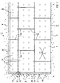
- Figur 1
- einen Innenraum eines Betriebsgebäudes einer kerntechnischen Anlage mit Metallplatten zum Strahlenschutz und
- Figur 2
- im Querschnitt eine Verbindungsstelle zwischen zwei Metallplatten.
- Gleiche Teile sind in beiden Figuren mit den gleichen Bezugszeichen versehen.
- Der Innenraum 1, der in Figur 1 anhand einer seiner Innenwände 2 in Aufsicht und anhand einer seiner Innenwände 2, seiner Raumdecke 4 und seines Bodens 6 im Querschnitt dargestellt ist, ist Teil eines Betriebsgebäudes einer kerntechnischen Anlage. Im Ausführungsbeispiel handelt es sich bei dem Betriebsgebäude um ein Zwischenlager für schwach radioaktive Abfälle, die vor einer Endlagerung einer Zwischenbehandlung zuzuführen sind. Alternativ kann es sich beim Betriebsgebäude aber auch um jedes andere Betriebsgebäude einer kerntechnischen Anlage handeln, wie beispielsweise um eine Abfallbehandlungsanlage oder um eine Anlage zur Brennelementeherstellung.
- Jede Innenwand 2 des Innneraums 1 weist eine Verkleidung 8 zum Strahlenschutz auf. Darüber hinaus ist auch die Decke 4 des Innenraums 1 mit einer Verkleidung 10 zum Strahlenschutz ausgerüstet. Der Fußboden 6 des Innenraums 1 weist an seiner Oberfläche einen dekontaminierenden Anstrich 12 auf.
- Die Verkleidung 8 jeder Innenwand 2 umfaßt eine Anzahl von Metallplatten 14, von denen jede mittels einer Anzahl von Betonankern 16 an der jeweiligen Innenwand 2 befestigt ist. Um eine hohe Abschirmwirkung gegenüber radioaktiver Strahlung zu erzielen, bestehen die Metallplatten 14 aus einem Metall hoher Dichte. Im Ausführungsbeispiel ist als Metall aus fertigungstechnischen Gründen Stahl gewählt, es kann jedoch auch ein beliebiges anderes Material mit hoher Dichte wie beispielsweise Blei sein. Jeweils zwei benachbarte Metallplatten 14 sind über eine Schraubverbindung 20 miteinander verbunden (Figur 2). Die Schraubverbindung 20 ist dabei an der dem Beton der jeweiligen Innenwand 2 zugewandten Seite der Metallplatten 14 angeordnet.
- Zur Abdichtung der Fugen 22 zwischen jeweils zwei Metallplatten 14 ist für jede Fuge 22 ein Fugenblech 24 vorgesehen, das die jeweilige Fuge 22 überdeckt. Die Fugenbleche 24 sind dabei ebenfalls auf der dem Beton der jeweiligen Innenwand 2 zugewandten Seite der jeweiligen Metallplatten 14 angeordnet.
- Zur Errichtung einer derartigen verkleideten Innenwand 2 des Innenraums 1 werden zunächst die Metallplatten 14 über die jeweiligen Schraubverbindungen 20 miteinander verbunden, so daß die vollständige Verkleidung 8 für die jeweilige Innenwand 2 entsteht. Auf diese Weise ist die Verkleidung 8 auch vorfertigbar. Sodann wird die Verkleidung 8 in ihrer endgültigen Lage positioniert, wobei die untersten Metallplatten 14 das Gewicht der Verkleidung 8 tragen. Nach der Errichtung der Verkleidung 8 wird die Innenwand 2 aus Beton gegossen, wobei die Verkleidung 8 als Schalung dient. Beim Gießen des Betons der Innenwand 2 umschließt dieser die an den Metallplatten 14 angeordneten Betonanker 16 derart, daß diese dauerhaft fixiert sind. Somit entsteht eine dauerhafte Kombination oder Verbindung der Verkleidung 8 mit der Innenwand 2.
- Aufgrund der Kombination der Verkleidung 8 mit der Innenwand 2 kann die Innenwand 2 bei hohem Abschirmungseffekt in konventioneller Wandstärke von etwa 0,4 m und somit besonders raumsparend ausgeführt sein. Im Gegensatz zu herkömmlichen Innenwänden eines derartigen Innenraumes, die mit vergrößerter Wandstärke von etwa 0,6 m und in Schwerbeton ausgeführt sein müssen, ist für die Errichtung einer derartigen Innenwand 2 keine Sonderzulassung erforderlich. Aufgrund der einfachen Montierbarkeit der Verkleidung 8 ist zudem eine besonders kurze Bauzeit bei der Errichtung einer derartigen abschirmungswirksamen Innenwand 2 erreichbar. Der Aufbau der Verkleidung 8 aus miteinander verschraubbaren Metallplatten 14 bedingt zudem eine hohe Flexibilität bei der Konzeption der Verkleidung 8. Daher ist eine derartige Verkleidung 8 auch in Kombination mit einer bereits existierenden Innenwand 2 in der Art einer Nachrüstung einsetzbar. In diesem Fall werden als Befestigungselemente beispielsweise Durchsteckanker oder Dübel verwendet.
Claims (6)
- Betriebsgebäude einer kerntechnischen Anlage mit einen Innenraum (1), der an mindestens einer seiner Innenwände (2) eine Verkleidung (8) zum Strahlenschutz aufweist.
- Betriebsgebäude nach Anspruch 1, dessen Innenraum (1) an seiner Decke (4) eine Verkleidung (10) zum Strahlenschutz aufweist.
- Betriebsgebäude nach Anspruch 1 oder 2, dessen Verkleidung (8, 10) eine Anzahl von Metallplatten (14) umfaßt, von denen jede mittels einer Anzahl von Betonankern (16) an einer Innenwand (2) befestigt ist.
- Betriebsgebäude nach Anspruch 3, bei dem eine Fuge (22) zwischen zwei Metallplatten (14) durch ein Fugenblech (24) überdeckt ist.
- Betriebsgebäude nach Anspruch 3 oder 4, bei dem jeweils zwei Metallplatten (14) über eine Schraubverbindung (20) miteinander verbunden sind.
- Metallplatte zur Verkleidung eines Innenraumes (1) eines Betriebsgebäudes einer kerntechnischen Anlage, die über eine Anzahl von Betonankern (16) an einer Innenwand (2) des Innenraumes (1) anbringbar ist.
Applications Claiming Priority (2)
| Application Number | Priority Date | Filing Date | Title |
|---|---|---|---|
| DE19619723 | 1996-05-15 | ||
| DE19619723 | 1996-05-15 |
Publications (2)
| Publication Number | Publication Date |
|---|---|
| EP0807937A1 true EP0807937A1 (de) | 1997-11-19 |
| EP0807937B1 EP0807937B1 (de) | 2010-10-06 |
Family
ID=7794462
Family Applications (1)
| Application Number | Title | Priority Date | Filing Date |
|---|---|---|---|
| EP97107948A Expired - Lifetime EP0807937B1 (de) | 1996-05-15 | 1997-05-15 | Betriebsgebäude einer kerntechnischen Anlage mit Innenraumverkleidung |
Country Status (3)
| Country | Link |
|---|---|
| EP (1) | EP0807937B1 (de) |
| DE (1) | DE59713045D1 (de) |
| ES (1) | ES2351683T3 (de) |
Citations (4)
| Publication number | Priority date | Publication date | Assignee | Title |
|---|---|---|---|---|
| CH543161A (de) * | 1972-02-28 | 1973-10-15 | Kowol Gmbh | Bauelement, insbesondere für strahlengefährdete Räume und Gegenstände |
| EP0257016A2 (de) * | 1986-07-24 | 1988-02-24 | Hermann Stöger | Abschirmvorrichtung zum Schutz vor Strahlung, Giftgasen od.dgl. |
| JPS6444896A (en) * | 1987-08-13 | 1989-02-17 | Tokuji Oshio | Wall panel |
| WO1993020561A1 (de) * | 1992-04-03 | 1993-10-14 | Siemens Aktiengesellschaft | Gasdichte schutzwand |
-
1997
- 1997-05-15 DE DE59713045T patent/DE59713045D1/de not_active Expired - Lifetime
- 1997-05-15 EP EP97107948A patent/EP0807937B1/de not_active Expired - Lifetime
- 1997-05-15 ES ES97107948T patent/ES2351683T3/es not_active Expired - Lifetime
Patent Citations (4)
| Publication number | Priority date | Publication date | Assignee | Title |
|---|---|---|---|---|
| CH543161A (de) * | 1972-02-28 | 1973-10-15 | Kowol Gmbh | Bauelement, insbesondere für strahlengefährdete Räume und Gegenstände |
| EP0257016A2 (de) * | 1986-07-24 | 1988-02-24 | Hermann Stöger | Abschirmvorrichtung zum Schutz vor Strahlung, Giftgasen od.dgl. |
| JPS6444896A (en) * | 1987-08-13 | 1989-02-17 | Tokuji Oshio | Wall panel |
| WO1993020561A1 (de) * | 1992-04-03 | 1993-10-14 | Siemens Aktiengesellschaft | Gasdichte schutzwand |
Non-Patent Citations (1)
| Title |
|---|
| PATENT ABSTRACTS OF JAPAN vol. 013, no. 242 (P - 880) 7 June 1989 (1989-06-07) * |
Also Published As
| Publication number | Publication date |
|---|---|
| EP0807937B1 (de) | 2010-10-06 |
| DE59713045D1 (de) | 2010-11-18 |
| ES2351683T3 (es) | 2011-02-09 |
Similar Documents
| Publication | Publication Date | Title |
|---|---|---|
| DE10327466B4 (de) | Baukörper für Strahlenschutzbauwerke | |
| DE2716388A1 (de) | Verbindung von platten | |
| DE3403537A1 (de) | Balkonfertig-bauelement fuer gebaeude | |
| DE29916463U1 (de) | Zweischalige Fertigteile zur Erstellung von Decken | |
| EP0807937B1 (de) | Betriebsgebäude einer kerntechnischen Anlage mit Innenraumverkleidung | |
| EP1890001A1 (de) | Sondertübbing für den Tunnelausbau | |
| DE2728544A1 (de) | Fertigbauteil in form eines in sich geschlossenen kastens mit rasterabmessungen | |
| DE2825375A1 (de) | Geschraubter grossraumsilo | |
| DE3302075A1 (de) | Spannbeton- oder stahlbetonbiegetraeger | |
| CH666076A5 (en) | Nuclear weapon survival shelter using concrete shell - having casing of prefabricated steel plates with continuous repeating profile and flat in transverse direction | |
| DE1659007A1 (de) | Vorrichtung zum Anschliessen von Stahlbetonbauteilen an in Wanderschalung hergestellte wandartige Stahlbetonbauteile | |
| DE2912131C2 (de) | Garage | |
| DE3326585A1 (de) | Rotationssymmetrischer sicherheitsbehaelter | |
| EP0064572A2 (de) | Silobau, insbesondere aus vorgefertigten Stahlbetonfertigteilen | |
| DE959761C (de) | Bauweise mit vereinheitlichten, vorgefertigten und raumhohen Wandteilen | |
| DE1658930A1 (de) | Anordnung zum Anschluss von vorgefertigten Stahlbetondeckenplatten an tragende Waende und aneinander | |
| DE3407346C2 (de) | Anordnung zur Nachrüstung von Tresoren gegen die Einwirkung von Sprengladungen | |
| AT16064U1 (de) | Wandkonstruktion | |
| DE3222943A1 (de) | Kernreaktoranlage | |
| EP0331642A2 (de) | Vorgefertigtes Eisenbeton-Bauelement | |
| DD240090A1 (de) | Wand- und/oder deckenkonstruktion fuer strahlengefaehrdete/strahlenbelastete raeume | |
| EP0659952A1 (de) | Rohrspindeltreppe sowie Anordnung aus mehreren Rohrspindeltreppen | |
| DE7810496U1 (de) | Fertigbauteil für eine Lärmschutzwand | |
| DE2127752A1 (en) | Radiation proofed building - for use in nuclear power stations | |
| DD208837B1 (de) | Montageverfahren zur herstellung hochbeanspruchter waende |
Legal Events
| Date | Code | Title | Description |
|---|---|---|---|
| PUAI | Public reference made under article 153(3) epc to a published international application that has entered the european phase |
Free format text: ORIGINAL CODE: 0009012 |
|
| AK | Designated contracting states |
Kind code of ref document: A1 Designated state(s): CH DE ES FR GB LI SE |
|
| 17P | Request for examination filed |
Effective date: 19971218 |
|
| RAP1 | Party data changed (applicant data changed or rights of an application transferred) |
Owner name: FRAMATOME ANP GMBH |
|
| RAP1 | Party data changed (applicant data changed or rights of an application transferred) |
Owner name: AREVA NP GMBH |
|
| RAP1 | Party data changed (applicant data changed or rights of an application transferred) |
Owner name: AREVA NP GMBH |
|
| GRAP | Despatch of communication of intention to grant a patent |
Free format text: ORIGINAL CODE: EPIDOSNIGR1 |
|
| RTI1 | Title (correction) |
Free format text: NUCLEAR UTILITY BUILDING COMPRISING AN INTERIOR LINED ROOM |
|
| GRAS | Grant fee paid |
Free format text: ORIGINAL CODE: EPIDOSNIGR3 |
|
| GRAA | (expected) grant |
Free format text: ORIGINAL CODE: 0009210 |
|
| AK | Designated contracting states |
Kind code of ref document: B1 Designated state(s): CH DE ES FR GB LI SE |
|
| REG | Reference to a national code |
Ref country code: GB Ref legal event code: FG4D Free format text: NOT ENGLISH |
|
| REG | Reference to a national code |
Ref country code: CH Ref legal event code: EP |
|
| REF | Corresponds to: |
Ref document number: 59713045 Country of ref document: DE Date of ref document: 20101118 Kind code of ref document: P |
|
| REG | Reference to a national code |
Ref country code: CH Ref legal event code: NV Representative=s name: E. BLUM & CO. AG PATENT- UND MARKENANWAELTE VSP |
|
| REG | Reference to a national code |
Ref country code: SE Ref legal event code: TRGR |
|
| REG | Reference to a national code |
Ref country code: ES Ref legal event code: FG2A Effective date: 20110128 |
|
| PLBE | No opposition filed within time limit |
Free format text: ORIGINAL CODE: 0009261 |
|
| STAA | Information on the status of an ep patent application or granted ep patent |
Free format text: STATUS: NO OPPOSITION FILED WITHIN TIME LIMIT |
|
| 26N | No opposition filed |
Effective date: 20110707 |
|
| REG | Reference to a national code |
Ref country code: DE Ref legal event code: R097 Ref document number: 59713045 Country of ref document: DE Effective date: 20110707 |
|
| REG | Reference to a national code |
Ref country code: DE Ref legal event code: R082 Ref document number: 59713045 Country of ref document: DE Representative=s name: TERGAU & WALKENHORST PATENTANWAELTE - RECHTSAN, DE |
|
| REG | Reference to a national code |
Ref country code: DE Ref legal event code: R082 Ref document number: 59713045 Country of ref document: DE Representative=s name: TERGAU & WALKENHORST PATENTANWAELTE PARTGMBB, DE Effective date: 20130618 Ref country code: DE Ref legal event code: R082 Ref document number: 59713045 Country of ref document: DE Representative=s name: TERGAU & WALKENHORST PATENTANWAELTE - RECHTSAN, DE Effective date: 20130618 Ref country code: DE Ref legal event code: R081 Ref document number: 59713045 Country of ref document: DE Owner name: AREVA GMBH, DE Free format text: FORMER OWNER: AREVA NP GMBH, 91052 ERLANGEN, DE Effective date: 20130618 |
|
| PGFP | Annual fee paid to national office [announced via postgrant information from national office to epo] |
Ref country code: GB Payment date: 20140520 Year of fee payment: 18 |
|
| PGFP | Annual fee paid to national office [announced via postgrant information from national office to epo] |
Ref country code: FR Payment date: 20140516 Year of fee payment: 18 Ref country code: ES Payment date: 20140521 Year of fee payment: 18 Ref country code: DE Payment date: 20140522 Year of fee payment: 18 Ref country code: CH Payment date: 20140522 Year of fee payment: 18 Ref country code: SE Payment date: 20140520 Year of fee payment: 18 |
|
| REG | Reference to a national code |
Ref country code: DE Ref legal event code: R119 Ref document number: 59713045 Country of ref document: DE |
|
| REG | Reference to a national code |
Ref country code: CH Ref legal event code: PL |
|
| GBPC | Gb: european patent ceased through non-payment of renewal fee |
Effective date: 20150515 |
|
| PG25 | Lapsed in a contracting state [announced via postgrant information from national office to epo] |
Ref country code: CH Free format text: LAPSE BECAUSE OF NON-PAYMENT OF DUE FEES Effective date: 20150531 Ref country code: LI Free format text: LAPSE BECAUSE OF NON-PAYMENT OF DUE FEES Effective date: 20150531 |
|
| REG | Reference to a national code |
Ref country code: FR Ref legal event code: ST Effective date: 20160129 |
|
| PG25 | Lapsed in a contracting state [announced via postgrant information from national office to epo] |
Ref country code: SE Free format text: LAPSE BECAUSE OF NON-PAYMENT OF DUE FEES Effective date: 20150516 |
|
| PG25 | Lapsed in a contracting state [announced via postgrant information from national office to epo] |
Ref country code: GB Free format text: LAPSE BECAUSE OF NON-PAYMENT OF DUE FEES Effective date: 20150515 Ref country code: DE Free format text: LAPSE BECAUSE OF NON-PAYMENT OF DUE FEES Effective date: 20151201 |
|
| PG25 | Lapsed in a contracting state [announced via postgrant information from national office to epo] |
Ref country code: FR Free format text: LAPSE BECAUSE OF NON-PAYMENT OF DUE FEES Effective date: 20150601 |
|
| REG | Reference to a national code |
Ref country code: ES Ref legal event code: FD2A Effective date: 20160628 |
|
| PG25 | Lapsed in a contracting state [announced via postgrant information from national office to epo] |
Ref country code: ES Free format text: LAPSE BECAUSE OF NON-PAYMENT OF DUE FEES Effective date: 20150516 |