EP0807756B2 - Conduit à carburant - Google Patents
Conduit à carburant Download PDFInfo
- Publication number
- EP0807756B2 EP0807756B2 EP97104608A EP97104608A EP0807756B2 EP 0807756 B2 EP0807756 B2 EP 0807756B2 EP 97104608 A EP97104608 A EP 97104608A EP 97104608 A EP97104608 A EP 97104608A EP 0807756 B2 EP0807756 B2 EP 0807756B2
- Authority
- EP
- European Patent Office
- Prior art keywords
- fuel
- pipe
- heat
- line
- enlarged surface
- Prior art date
- Legal status (The legal status is an assumption and is not a legal conclusion. Google has not performed a legal analysis and makes no representation as to the accuracy of the status listed.)
- Expired - Lifetime
Links
- 239000000446 fuel Substances 0.000 title claims description 39
- 238000001816 cooling Methods 0.000 claims description 9
- 239000002828 fuel tank Substances 0.000 claims description 8
- 239000002184 metal Substances 0.000 claims description 3
- 238000001125 extrusion Methods 0.000 description 3
- 230000015572 biosynthetic process Effects 0.000 description 2
- 241000446313 Lamella Species 0.000 description 1
- 239000000498 cooling water Substances 0.000 description 1
- 230000001419 dependent effect Effects 0.000 description 1
- 230000000694 effects Effects 0.000 description 1
- 229920001971 elastomer Polymers 0.000 description 1
- 239000000806 elastomer Substances 0.000 description 1
- 238000009434 installation Methods 0.000 description 1
- 238000000034 method Methods 0.000 description 1
- 210000002105 tongue Anatomy 0.000 description 1
Images
Classifications
-
- F—MECHANICAL ENGINEERING; LIGHTING; HEATING; WEAPONS; BLASTING
- F28—HEAT EXCHANGE IN GENERAL
- F28D—HEAT-EXCHANGE APPARATUS, NOT PROVIDED FOR IN ANOTHER SUBCLASS, IN WHICH THE HEAT-EXCHANGE MEDIA DO NOT COME INTO DIRECT CONTACT
- F28D7/00—Heat-exchange apparatus having stationary tubular conduit assemblies for both heat-exchange media, the media being in contact with different sides of a conduit wall
-
- F—MECHANICAL ENGINEERING; LIGHTING; HEATING; WEAPONS; BLASTING
- F02—COMBUSTION ENGINES; HOT-GAS OR COMBUSTION-PRODUCT ENGINE PLANTS
- F02M—SUPPLYING COMBUSTION ENGINES IN GENERAL WITH COMBUSTIBLE MIXTURES OR CONSTITUENTS THEREOF
- F02M31/00—Apparatus for thermally treating combustion-air, fuel, or fuel-air mixture
- F02M31/20—Apparatus for thermally treating combustion-air, fuel, or fuel-air mixture for cooling
-
- F—MECHANICAL ENGINEERING; LIGHTING; HEATING; WEAPONS; BLASTING
- F28—HEAT EXCHANGE IN GENERAL
- F28D—HEAT-EXCHANGE APPARATUS, NOT PROVIDED FOR IN ANOTHER SUBCLASS, IN WHICH THE HEAT-EXCHANGE MEDIA DO NOT COME INTO DIRECT CONTACT
- F28D1/00—Heat-exchange apparatus having stationary conduit assemblies for one heat-exchange medium only, the media being in contact with different sides of the conduit wall, in which the other heat-exchange medium is a large body of fluid, e.g. domestic or motor car radiators
- F28D1/02—Heat-exchange apparatus having stationary conduit assemblies for one heat-exchange medium only, the media being in contact with different sides of the conduit wall, in which the other heat-exchange medium is a large body of fluid, e.g. domestic or motor car radiators with heat-exchange conduits immersed in the body of fluid
- F28D1/04—Heat-exchange apparatus having stationary conduit assemblies for one heat-exchange medium only, the media being in contact with different sides of the conduit wall, in which the other heat-exchange medium is a large body of fluid, e.g. domestic or motor car radiators with heat-exchange conduits immersed in the body of fluid with tubular conduits
- F28D1/053—Heat-exchange apparatus having stationary conduit assemblies for one heat-exchange medium only, the media being in contact with different sides of the conduit wall, in which the other heat-exchange medium is a large body of fluid, e.g. domestic or motor car radiators with heat-exchange conduits immersed in the body of fluid with tubular conduits the conduits being straight
-
- F—MECHANICAL ENGINEERING; LIGHTING; HEATING; WEAPONS; BLASTING
- F28—HEAT EXCHANGE IN GENERAL
- F28F—DETAILS OF HEAT-EXCHANGE AND HEAT-TRANSFER APPARATUS, OF GENERAL APPLICATION
- F28F1/00—Tubular elements; Assemblies of tubular elements
- F28F1/10—Tubular elements and assemblies thereof with means for increasing heat-transfer area, e.g. with fins, with projections, with recesses
- F28F1/12—Tubular elements and assemblies thereof with means for increasing heat-transfer area, e.g. with fins, with projections, with recesses the means being only outside the tubular element
- F28F1/14—Tubular elements and assemblies thereof with means for increasing heat-transfer area, e.g. with fins, with projections, with recesses the means being only outside the tubular element and extending longitudinally
- F28F1/22—Tubular elements and assemblies thereof with means for increasing heat-transfer area, e.g. with fins, with projections, with recesses the means being only outside the tubular element and extending longitudinally the means having portions engaging further tubular elements
-
- F—MECHANICAL ENGINEERING; LIGHTING; HEATING; WEAPONS; BLASTING
- F28—HEAT EXCHANGE IN GENERAL
- F28D—HEAT-EXCHANGE APPARATUS, NOT PROVIDED FOR IN ANOTHER SUBCLASS, IN WHICH THE HEAT-EXCHANGE MEDIA DO NOT COME INTO DIRECT CONTACT
- F28D21/00—Heat-exchange apparatus not covered by any of the groups F28D1/00 - F28D20/00
- F28D2021/0019—Other heat exchangers for particular applications; Heat exchange systems not otherwise provided for
- F28D2021/008—Other heat exchangers for particular applications; Heat exchange systems not otherwise provided for for vehicles
- F28D2021/0087—Fuel coolers
-
- Y—GENERAL TAGGING OF NEW TECHNOLOGICAL DEVELOPMENTS; GENERAL TAGGING OF CROSS-SECTIONAL TECHNOLOGIES SPANNING OVER SEVERAL SECTIONS OF THE IPC; TECHNICAL SUBJECTS COVERED BY FORMER USPC CROSS-REFERENCE ART COLLECTIONS [XRACs] AND DIGESTS
- Y02—TECHNOLOGIES OR APPLICATIONS FOR MITIGATION OR ADAPTATION AGAINST CLIMATE CHANGE
- Y02T—CLIMATE CHANGE MITIGATION TECHNOLOGIES RELATED TO TRANSPORTATION
- Y02T10/00—Road transport of goods or passengers
- Y02T10/10—Internal combustion engine [ICE] based vehicles
- Y02T10/12—Improving ICE efficiencies
Definitions
- the invention relates to a motor vehicle according to the preamble of claim 1.
- WO-A-94/23257 is already a motor vehicle with an engine and a fuel tank known in which between the engine and the fuel tank arranged a fuel line system is.
- the fuel line system has a flow and a return line on.
- a section of the known Fuel line system is with at least one section a thermally conductive surface enlargement for cooling the air flowing in the fuel lines Fuel provided.
- the known thermally conductive Surface enlargement consists of cooling fins, which are made of a light metal.
- Extruded profile tube known for heat exchangers, composed of at least two profile halves is dense along two outer longitudinal edges connected to each other.
- the extruded profile tube can be inside and / or outside with the heat exchange surface be provided magnifying elements.
- These Elements can be z. B. from longitudinal ribs or preferably in longitudinal rows successive individual Tongues, wings or protrusions exist, by cuts in longitudinal ribs and by turning, Turning or the like can be formed.
- the extruded profile tube is primarily for heat exchangers, z. B. for radiators of motor vehicles determined. In these heat exchangers, the cooling water of the engine by the airstream and / or by a Fan cooled.
- the object of the invention is a motor vehicle to provide, in a simple way, a fuel cooling is possible.
- An air cooling takes place in the fuel lines located fuel in that as a common surface enlargement for the flow line and the return line a plantetblech or a profile formed as an extrusion cross-sectional increase the line is provided, which only partially is trained.
- the thermally conductive surface enlargement is on the outer surface of the body of a motor vehicle, in particular on the floor panel, arranged.
- the surface enlargement takes place in one Embodiment by the formation of additional surfaces, d. H. of components such as ribs coming from the fuel line stand out and / or of varnishleitblechen, which are connected to the fuel line.
- additional surfaces d. H. of components such as ribs coming from the fuel line stand out and / or of varnishleitblechen, which are connected to the fuel line.
- the surface enlargement take place in that the fuel line a larger Cross section has. Further embodiments arise by combinations of the aforementioned Options.
- the surface enlargement according to the invention is sized so that the temperature of the above Return line returning fuel so far is cooled, that the permissible continuous operating temperature of the fuel tank and / or its installation units is not exceeded.
- the fuel line system by a corresponding Mounting type acoustic from the body of the motor vehicle decoupled.
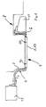
- the fuel line system 1 shows a fuel line system 1, that of at least one supply line 2 and at least a return line 3 consists.
- the fuel line system 1 is in the embodiment shown in FIG divided into three sections 4, 5, 6. Of the Front and rear section 4 and 6 is usually formed as a tube, for example, a Elastomer hose may be.
- the middle section 5 is used in particular for cooling in the return line 3 contained fuel.
- the middle section 5 is at the bottom or bottom plate 7 of the body 8 of a motor vehicle, for example via Clips 9 and 10 attached acoustically decoupled.
- the Fuel line system 1 promotes the fuel from a Fuel tank 11 via the flow line 2 to an engine 12.
- the engine 12 is not consumed Fuel is very hot and gets over the return line 3 returned to the fuel tank 11.
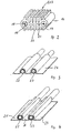
- the middle one Section 5 is with a thermally conductive surface enlargement 13 provided. embodiments Such surface enlargement 13 are in the Fig. 2 to 5 shown.
- Fig. 2 is a perspective sectional view a surface enlargement 13 is shown, which is designed as an extruded tube profile 16.
- the Extrusion tube profile 16 has two lines 17 and 18th on, in which the fuel forward or backward.
- the Return line 18 is a second line 19 with a smaller cross section in contact with the surface enlargement 13 arranged.
- the Surface enlargement 13 of Fig. 3 consists of Longitudinal ribs 20, which are integral to a transverse web 21st are formed.
- the pros and Return lines 17, 18, 19 are considered a common profile produced. From Fig. 2 is with respect to the Leads 18 and 19 also show that the surface enlargement 13 by a cross-sectional increase of Normal line 19 with respect to the enlarged line 18 can take place. In addition to the surface enlargement 13 has the cross-sectional increase the further effect that the fuel in the fuel line at a larger cross section slower through the pipe flows, so that the residence time of the fuel in the cooling section 5 is increased and thus more Heat can be radiated to the environment.
- the Connections from the extruded tube 16 to the profile Front and rear sections 4 and 5 are over Pressed or screwed nozzles.
- FIGS. 3 and 4 show an embodiment of the cooling section 5, in which the heat-conductive lines 22 and 23 are surrounded by a heat-conducting plate 24 or a plurality of heat-conducting plates 25, 26, 27.
- the nickelleitbleche 24; 25, 26, 27 are simultaneously used as c w value coverage of the underside 7 of the body 8 of a motor vehicle.
- the heat conducting plates 24; 25, 26, 27 and arranged therein lines 22, 23 acoustically decoupled fixed to the body 8.
Landscapes
- Engineering & Computer Science (AREA)
- Physics & Mathematics (AREA)
- Mechanical Engineering (AREA)
- General Engineering & Computer Science (AREA)
- Thermal Sciences (AREA)
- Geometry (AREA)
- Chemical & Material Sciences (AREA)
- Combustion & Propulsion (AREA)
- Cooling, Air Intake And Gas Exhaust, And Fuel Tank Arrangements In Propulsion Units (AREA)
Claims (3)
- Véhicule automobile équipé d'un système de conduites de carburant (1) ayant au moins une conduite d'alimentation et une conduite de retour (2, 3) respectivement installées entre le moteur (12) et le réservoir de carburant (11) du véhicule, à la surface extérieure de la carrosserie (8), notamment contre la tôle de plancher (7) en étant désaccouplées acoustiquement,
le système de conduite de carburant (1) ayant au moins un segment (5) avec une surface agrandie (13) thermoconductrice pour refroidir le carburant par l'air,
l'augmentation de surface (13) étant dimensionnée suivant les valeurs spécifiques du véhicule pour que le carburant de retour au réservoir (11) soit refroidi à une température de fonctionnement autorisée, alors que
l'augmentation de surface thermoconductrice (13) est composée d'éléments (20, 21) en saillie de la conduite (17, 18, 19), et fabriqués en métal léger,
caractérisé en ce que
l'augmentation de surface commune (13) de la conduite d'alimentation et de la conduite de retour (2, 3) est constituée par une tôle thermoconductrice (24, 25, 26, 27) ou par une augmentation de section de la conduite en forme de profilé extrudé à la presse (16). - Système de conduite de carburant selon la revendication 1,
caractérisé en ce que
la conduite (18) assurant l'augmentation de surface (13) peut être coupée ou branchée en fonction de la température. - Système de conduite de carburant selon l'une des revendications 1 ou 2,
caractérisé en ce que
la tôle thermoconductrice (24, 25, 26, 27) est constituée d'une ou plusieurs tôles.
Applications Claiming Priority (2)
| Application Number | Priority Date | Filing Date | Title |
|---|---|---|---|
| DE19619934A DE19619934A1 (de) | 1996-05-17 | 1996-05-17 | Kraftstoffleitungssystem |
| DE19619934 | 1996-05-17 |
Publications (4)
| Publication Number | Publication Date |
|---|---|
| EP0807756A2 EP0807756A2 (fr) | 1997-11-19 |
| EP0807756A3 EP0807756A3 (fr) | 1998-04-01 |
| EP0807756B1 EP0807756B1 (fr) | 2000-07-05 |
| EP0807756B2 true EP0807756B2 (fr) | 2005-03-16 |
Family
ID=7794584
Family Applications (1)
| Application Number | Title | Priority Date | Filing Date |
|---|---|---|---|
| EP97104608A Expired - Lifetime EP0807756B2 (fr) | 1996-05-17 | 1997-03-18 | Conduit à carburant |
Country Status (2)
| Country | Link |
|---|---|
| EP (1) | EP0807756B2 (fr) |
| DE (2) | DE19619934A1 (fr) |
Families Citing this family (15)
| Publication number | Priority date | Publication date | Assignee | Title |
|---|---|---|---|---|
| DE19729857A1 (de) * | 1997-07-11 | 1999-01-14 | Volkswagen Ag | Kraftfahrzeug mit Unterbodenwärmetauscher |
| FR2774462B1 (fr) * | 1998-01-30 | 2000-04-14 | Peugeot | Echangeur refroidisseur de fluide |
| FR2774463A1 (fr) * | 1998-01-30 | 1999-08-06 | Peugeot | Module echangeur refroidisseur de fluide et utilisation du module echangeur refroidisseur |
| FR2774635B1 (fr) * | 1998-02-09 | 2000-04-21 | Valeo Thermique Moteur Sa | Dispositif de refroidissement du carburant d'un moteur de vehicule automobile |
| DE19815167B4 (de) * | 1998-04-04 | 2006-11-23 | Adam Opel Ag | Kraftstoffleitungssystem |
| DK79298A (da) | 1998-06-08 | 1999-12-09 | Norsk Hydro As | Profil for køling af brændstof, en brændstofledning samt en fremgangsmåde til fremstilling heraf |
| DE19916530A1 (de) * | 1999-04-13 | 2000-10-19 | Mannesmann Vdo Ag | Einrichtung zur Versorgung einer Brennkraftmaschine eines Kraftfahrzeuges mit Kraftstoff |
| SE9901437L (sv) * | 1999-04-22 | 2000-05-08 | Scania Cv Ab | Bränsletank |
| US7011142B2 (en) | 2000-12-21 | 2006-03-14 | Dana Canada Corporation | Finned plate heat exchanger |
| CA2329408C (fr) | 2000-12-21 | 2007-12-04 | Long Manufacturing Ltd. | Echangeur de chaleur a plaques a ailettes |
| BR0211048A (pt) | 2001-05-01 | 2004-07-20 | Julian Romero-Beltran | Trocador de calor do tipo de tubos e placas |
| CA2392610C (fr) | 2002-07-05 | 2010-11-02 | Long Manufacturing Ltd. | Echangeur de chaleur refroidi par parois cloisonnees |
| CA2425233C (fr) | 2003-04-11 | 2011-11-15 | Dana Canada Corporation | Echangeur thermique a plaques a ailettes a refroidissement sur surface froide |
| US7182125B2 (en) | 2003-11-28 | 2007-02-27 | Dana Canada Corporation | Low profile heat exchanger with notched turbulizer |
| DE102016123323B3 (de) * | 2016-12-02 | 2018-03-01 | Eberspächer Climate Control Systems GmbH & Co. KG | Fahrzeug |
Family Cites Families (17)
| Publication number | Priority date | Publication date | Assignee | Title |
|---|---|---|---|---|
| US3294148A (en) * | 1966-12-27 | Fuel feeding system for internal combustion engines | ||
| US2969110A (en) * | 1959-03-12 | 1961-01-24 | Exxon Research Engineering Co | Fuel delivery system for automotive vehicles |
| FR1479486A (fr) * | 1966-03-14 | 1967-05-05 | Tube à profil spécial pour la constitution d'échangeurs thermiques | |
| CH606958A5 (en) * | 1976-12-02 | 1978-11-30 | Pierre Chuard | Tube and plate heat exchanger unit |
| IT1156963B (it) * | 1978-04-17 | 1987-02-04 | Fiat Veicoli Ind | Sistema per l'alimentazione del combustibile ad un motore a combustione interna |
| EP0038710A1 (fr) * | 1980-04-23 | 1981-10-28 | Barry William Wilder | Dispositif de refroidissement de l'essence pour moteurs à combustion interne |
| DE3153101C2 (de) * | 1981-01-02 | 1985-09-26 | Daimler-Benz Ag, 7000 Stuttgart | Kraftstoffkühler |
| JPS59155564A (ja) * | 1983-02-24 | 1984-09-04 | Toyota Motor Corp | 燃料噴射式エンジンの燃料分配管 |
| DE3704215C2 (de) * | 1987-02-11 | 1995-11-30 | Laengerer & Reich Kuehler | Strangpreßprofilrohr für Wärmeaustauscher |
| DE3735915A1 (de) * | 1987-10-23 | 1989-05-03 | Wieland Werke Ag | Waermeaustauscher |
| DE3740811A1 (de) * | 1987-12-02 | 1989-06-15 | Zdenek Struhovsky | Kraftstoffkuehler fuer eine brennkraftmaschine |
| DE3800296A1 (de) * | 1988-01-08 | 1989-07-20 | Porsche Ag | Kuehlvorrichtung an einem kraftfahrzeug |
| DE3912534C2 (de) * | 1989-04-17 | 1994-07-14 | Hansa Metallwerke Ag | Benzinkühler |
| JPH0343653A (ja) * | 1989-07-08 | 1991-02-25 | Nippondenso Co Ltd | 燃料冷却装置 |
| JPH04132446U (ja) * | 1991-05-29 | 1992-12-08 | 本田技研工業株式会社 | 自動車のガソリン冷却装置 |
| DE4141689C2 (de) * | 1991-12-18 | 1997-01-30 | Audi Ag | Vorrichtung zur Halterung einer Leitung an einer Wand eines Kraftfahrzeuges |
| WO1994023257A1 (fr) * | 1993-03-29 | 1994-10-13 | Melanesia International Trust Company Limited | Ensemble echangeur de chaleur |
-
1996
- 1996-05-17 DE DE19619934A patent/DE19619934A1/de not_active Withdrawn
-
1997
- 1997-03-18 DE DE59701962T patent/DE59701962D1/de not_active Expired - Lifetime
- 1997-03-18 EP EP97104608A patent/EP0807756B2/fr not_active Expired - Lifetime
Also Published As
| Publication number | Publication date |
|---|---|
| DE19619934A1 (de) | 1997-11-20 |
| EP0807756A2 (fr) | 1997-11-19 |
| EP0807756A3 (fr) | 1998-04-01 |
| EP0807756B1 (fr) | 2000-07-05 |
| DE59701962D1 (de) | 2000-08-10 |
Similar Documents
| Publication | Publication Date | Title |
|---|---|---|
| EP0807756B2 (fr) | Conduit à carburant | |
| DE69720347T3 (de) | Kombinierter Wärmetauscher | |
| EP0818663B1 (fr) | Echangeur de chaleur, en particulier radiateur | |
| DE19755095A1 (de) | Kraftfahrzeug | |
| DE102019205575A1 (de) | Vorrichtung zur Kühlung einer Fahrzeugbatterie | |
| EP0582835A1 (fr) | Echangeur de chaleur | |
| EP0890810B1 (fr) | Véhicule automobile comprenant un échangeur de chaleur sous le plancher | |
| EP0214517B1 (fr) | Circuit de chauffage à accumulateur de chaleur pour véhicules à moteurs | |
| DE69905862T2 (de) | Wärmetauscher mit biegsamen rohren | |
| DE4431107C1 (de) | Wärmetauscheranordnung zur Beheizung der Kabine von Kraftfahrzeugen mit der Abwärme des Antriebsmotors | |
| DE2606507A1 (de) | Klimaanlage | |
| DE69317086T2 (de) | Fahrzeugkühler | |
| EP1083072B1 (fr) | Dispositif de refroidissement pour un moteur à combustion | |
| EP1492990A2 (fr) | Echangeur de chaleur et systeme de refroidissement | |
| DE10328458A1 (de) | Niedrigtemperatur-Kühler für ein Kraftfahrzeug zur Kühlung mehrerer Bauteile | |
| DE102007008884A1 (de) | Heizkörper | |
| DE1655069A1 (de) | Waermeaustauscher fuer die Heizung und Kuehlung von Fahrzeugen | |
| DE102007027250B4 (de) | Kraftfahrzeug | |
| DE3611713C1 (en) | Radiator fan system in a motor vehicle | |
| DE102004049670B4 (de) | Kraftstoffkühler, Kraftfahrzeug mit einem derartigen Kraftstoffkühler | |
| AT397859B (de) | Wärmetauscher | |
| DE20304501U1 (de) | Fussbodenheizung für Wohnwagen oder Reisemobile | |
| DE102007024038A1 (de) | Wärmetauscher | |
| DE60309828T2 (de) | Heizanlage | |
| DE10142512B4 (de) | Elektrische Heizvorrichtung für Kraftfahrzeuge |
Legal Events
| Date | Code | Title | Description |
|---|---|---|---|
| PUAI | Public reference made under article 153(3) epc to a published international application that has entered the european phase |
Free format text: ORIGINAL CODE: 0009012 |
|
| AK | Designated contracting states |
Kind code of ref document: A2 Designated state(s): DE FR GB IT |
|
| PUAL | Search report despatched |
Free format text: ORIGINAL CODE: 0009013 |
|
| AK | Designated contracting states |
Kind code of ref document: A3 Designated state(s): DE FR GB IT |
|
| 17P | Request for examination filed |
Effective date: 19980915 |
|
| 17Q | First examination report despatched |
Effective date: 19990120 |
|
| GRAG | Despatch of communication of intention to grant |
Free format text: ORIGINAL CODE: EPIDOS AGRA |
|
| GRAG | Despatch of communication of intention to grant |
Free format text: ORIGINAL CODE: EPIDOS AGRA |
|
| GRAH | Despatch of communication of intention to grant a patent |
Free format text: ORIGINAL CODE: EPIDOS IGRA |
|
| RTI1 | Title (correction) |
Free format text: FUEL CONDUIT |
|
| 17Q | First examination report despatched |
Effective date: 19990120 |
|
| RIN1 | Information on inventor provided before grant (corrected) |
Inventor name: CHRISTIAN, TREML Inventor name: GUENTHER, TUSCHL |
|
| GRAH | Despatch of communication of intention to grant a patent |
Free format text: ORIGINAL CODE: EPIDOS IGRA |
|
| GRAA | (expected) grant |
Free format text: ORIGINAL CODE: 0009210 |
|
| AK | Designated contracting states |
Kind code of ref document: B1 Designated state(s): DE FR GB IT |
|
| GBT | Gb: translation of ep patent filed (gb section 77(6)(a)/1977) |
Effective date: 20000705 |
|
| REF | Corresponds to: |
Ref document number: 59701962 Country of ref document: DE Date of ref document: 20000810 |
|
| ET | Fr: translation filed | ||
| ITF | It: translation for a ep patent filed | ||
| PLBQ | Unpublished change to opponent data |
Free format text: ORIGINAL CODE: EPIDOS OPPO |
|
| PLBI | Opposition filed |
Free format text: ORIGINAL CODE: 0009260 |
|
| 26 | Opposition filed |
Opponent name: NORSK HYDRO ASA Effective date: 20010402 Opponent name: AUDI AG Effective date: 20010331 |
|
| PLBF | Reply of patent proprietor to notice(s) of opposition |
Free format text: ORIGINAL CODE: EPIDOS OBSO |
|
| PLBF | Reply of patent proprietor to notice(s) of opposition |
Free format text: ORIGINAL CODE: EPIDOS OBSO |
|
| REG | Reference to a national code |
Ref country code: GB Ref legal event code: IF02 |
|
| PLBC | Reply to examination report in opposition received |
Free format text: ORIGINAL CODE: EPIDOSNORE3 |
|
| PUAH | Patent maintained in amended form |
Free format text: ORIGINAL CODE: 0009272 |
|
| STAA | Information on the status of an ep patent application or granted ep patent |
Free format text: STATUS: PATENT MAINTAINED AS AMENDED |
|
| 27A | Patent maintained in amended form |
Effective date: 20050316 |
|
| AK | Designated contracting states |
Kind code of ref document: B2 Designated state(s): DE FR GB IT |
|
| GBTA | Gb: translation of amended ep patent filed (gb section 77(6)(b)/1977) | ||
| ET3 | Fr: translation filed ** decision concerning opposition | ||
| PLAB | Opposition data, opponent's data or that of the opponent's representative modified |
Free format text: ORIGINAL CODE: 0009299OPPO |
|
| PGFP | Annual fee paid to national office [announced via postgrant information from national office to epo] |
Ref country code: DE Payment date: 20140319 Year of fee payment: 18 |
|
| PGFP | Annual fee paid to national office [announced via postgrant information from national office to epo] |
Ref country code: IT Payment date: 20140327 Year of fee payment: 18 |
|
| PGFP | Annual fee paid to national office [announced via postgrant information from national office to epo] |
Ref country code: GB Payment date: 20140327 Year of fee payment: 18 |
|
| PGFP | Annual fee paid to national office [announced via postgrant information from national office to epo] |
Ref country code: FR Payment date: 20140327 Year of fee payment: 18 |
|
| REG | Reference to a national code |
Ref country code: DE Ref legal event code: R119 Ref document number: 59701962 Country of ref document: DE |
|
| GBPC | Gb: european patent ceased through non-payment of renewal fee |
Effective date: 20150318 |
|
| PG25 | Lapsed in a contracting state [announced via postgrant information from national office to epo] |
Ref country code: IT Free format text: LAPSE BECAUSE OF NON-PAYMENT OF DUE FEES Effective date: 20150318 |
|
| REG | Reference to a national code |
Ref country code: FR Ref legal event code: ST Effective date: 20151130 |
|
| PG25 | Lapsed in a contracting state [announced via postgrant information from national office to epo] |
Ref country code: GB Free format text: LAPSE BECAUSE OF NON-PAYMENT OF DUE FEES Effective date: 20150318 Ref country code: DE Free format text: LAPSE BECAUSE OF NON-PAYMENT OF DUE FEES Effective date: 20151001 |
|
| PG25 | Lapsed in a contracting state [announced via postgrant information from national office to epo] |
Ref country code: FR Free format text: LAPSE BECAUSE OF NON-PAYMENT OF DUE FEES Effective date: 20150331 |