EP0807756B2 - Fuel conduit - Google Patents
Fuel conduit Download PDFInfo
- Publication number
- EP0807756B2 EP0807756B2 EP97104608A EP97104608A EP0807756B2 EP 0807756 B2 EP0807756 B2 EP 0807756B2 EP 97104608 A EP97104608 A EP 97104608A EP 97104608 A EP97104608 A EP 97104608A EP 0807756 B2 EP0807756 B2 EP 0807756B2
- Authority
- EP
- European Patent Office
- Prior art keywords
- fuel
- pipe
- heat
- line
- enlarged surface
- Prior art date
- Legal status (The legal status is an assumption and is not a legal conclusion. Google has not performed a legal analysis and makes no representation as to the accuracy of the status listed.)
- Expired - Lifetime
Links
- 239000000446 fuel Substances 0.000 title claims description 39
- 238000001816 cooling Methods 0.000 claims description 9
- 239000002828 fuel tank Substances 0.000 claims description 8
- 239000002184 metal Substances 0.000 claims description 3
- 238000001125 extrusion Methods 0.000 description 3
- 230000015572 biosynthetic process Effects 0.000 description 2
- 241000446313 Lamella Species 0.000 description 1
- 239000000498 cooling water Substances 0.000 description 1
- 230000001419 dependent effect Effects 0.000 description 1
- 230000000694 effects Effects 0.000 description 1
- 229920001971 elastomer Polymers 0.000 description 1
- 239000000806 elastomer Substances 0.000 description 1
- 238000009434 installation Methods 0.000 description 1
- 238000000034 method Methods 0.000 description 1
- 210000002105 tongue Anatomy 0.000 description 1
Images
Classifications
-
- F—MECHANICAL ENGINEERING; LIGHTING; HEATING; WEAPONS; BLASTING
- F28—HEAT EXCHANGE IN GENERAL
- F28D—HEAT-EXCHANGE APPARATUS, NOT PROVIDED FOR IN ANOTHER SUBCLASS, IN WHICH THE HEAT-EXCHANGE MEDIA DO NOT COME INTO DIRECT CONTACT
- F28D7/00—Heat-exchange apparatus having stationary tubular conduit assemblies for both heat-exchange media, the media being in contact with different sides of a conduit wall
-
- F—MECHANICAL ENGINEERING; LIGHTING; HEATING; WEAPONS; BLASTING
- F02—COMBUSTION ENGINES; HOT-GAS OR COMBUSTION-PRODUCT ENGINE PLANTS
- F02M—SUPPLYING COMBUSTION ENGINES IN GENERAL WITH COMBUSTIBLE MIXTURES OR CONSTITUENTS THEREOF
- F02M31/00—Apparatus for thermally treating combustion-air, fuel, or fuel-air mixture
- F02M31/20—Apparatus for thermally treating combustion-air, fuel, or fuel-air mixture for cooling
-
- F—MECHANICAL ENGINEERING; LIGHTING; HEATING; WEAPONS; BLASTING
- F28—HEAT EXCHANGE IN GENERAL
- F28D—HEAT-EXCHANGE APPARATUS, NOT PROVIDED FOR IN ANOTHER SUBCLASS, IN WHICH THE HEAT-EXCHANGE MEDIA DO NOT COME INTO DIRECT CONTACT
- F28D1/00—Heat-exchange apparatus having stationary conduit assemblies for one heat-exchange medium only, the media being in contact with different sides of the conduit wall, in which the other heat-exchange medium is a large body of fluid, e.g. domestic or motor car radiators
- F28D1/02—Heat-exchange apparatus having stationary conduit assemblies for one heat-exchange medium only, the media being in contact with different sides of the conduit wall, in which the other heat-exchange medium is a large body of fluid, e.g. domestic or motor car radiators with heat-exchange conduits immersed in the body of fluid
- F28D1/04—Heat-exchange apparatus having stationary conduit assemblies for one heat-exchange medium only, the media being in contact with different sides of the conduit wall, in which the other heat-exchange medium is a large body of fluid, e.g. domestic or motor car radiators with heat-exchange conduits immersed in the body of fluid with tubular conduits
- F28D1/053—Heat-exchange apparatus having stationary conduit assemblies for one heat-exchange medium only, the media being in contact with different sides of the conduit wall, in which the other heat-exchange medium is a large body of fluid, e.g. domestic or motor car radiators with heat-exchange conduits immersed in the body of fluid with tubular conduits the conduits being straight
-
- F—MECHANICAL ENGINEERING; LIGHTING; HEATING; WEAPONS; BLASTING
- F28—HEAT EXCHANGE IN GENERAL
- F28F—DETAILS OF HEAT-EXCHANGE AND HEAT-TRANSFER APPARATUS, OF GENERAL APPLICATION
- F28F1/00—Tubular elements; Assemblies of tubular elements
- F28F1/10—Tubular elements and assemblies thereof with means for increasing heat-transfer area, e.g. with fins, with projections, with recesses
- F28F1/12—Tubular elements and assemblies thereof with means for increasing heat-transfer area, e.g. with fins, with projections, with recesses the means being only outside the tubular element
- F28F1/14—Tubular elements and assemblies thereof with means for increasing heat-transfer area, e.g. with fins, with projections, with recesses the means being only outside the tubular element and extending longitudinally
- F28F1/22—Tubular elements and assemblies thereof with means for increasing heat-transfer area, e.g. with fins, with projections, with recesses the means being only outside the tubular element and extending longitudinally the means having portions engaging further tubular elements
-
- F—MECHANICAL ENGINEERING; LIGHTING; HEATING; WEAPONS; BLASTING
- F28—HEAT EXCHANGE IN GENERAL
- F28D—HEAT-EXCHANGE APPARATUS, NOT PROVIDED FOR IN ANOTHER SUBCLASS, IN WHICH THE HEAT-EXCHANGE MEDIA DO NOT COME INTO DIRECT CONTACT
- F28D21/00—Heat-exchange apparatus not covered by any of the groups F28D1/00 - F28D20/00
- F28D2021/0019—Other heat exchangers for particular applications; Heat exchange systems not otherwise provided for
- F28D2021/008—Other heat exchangers for particular applications; Heat exchange systems not otherwise provided for for vehicles
- F28D2021/0087—Fuel coolers
-
- Y—GENERAL TAGGING OF NEW TECHNOLOGICAL DEVELOPMENTS; GENERAL TAGGING OF CROSS-SECTIONAL TECHNOLOGIES SPANNING OVER SEVERAL SECTIONS OF THE IPC; TECHNICAL SUBJECTS COVERED BY FORMER USPC CROSS-REFERENCE ART COLLECTIONS [XRACs] AND DIGESTS
- Y02—TECHNOLOGIES OR APPLICATIONS FOR MITIGATION OR ADAPTATION AGAINST CLIMATE CHANGE
- Y02T—CLIMATE CHANGE MITIGATION TECHNOLOGIES RELATED TO TRANSPORTATION
- Y02T10/00—Road transport of goods or passengers
- Y02T10/10—Internal combustion engine [ICE] based vehicles
- Y02T10/12—Improving ICE efficiencies
Definitions
- the invention relates to a motor vehicle according to the preamble of claim 1.
- WO-A-94/23257 is already a motor vehicle with an engine and a fuel tank known in which between the engine and the fuel tank arranged a fuel line system is.
- the fuel line system has a flow and a return line on.
- a section of the known Fuel line system is with at least one section a thermally conductive surface enlargement for cooling the air flowing in the fuel lines Fuel provided.
- the known thermally conductive Surface enlargement consists of cooling fins, which are made of a light metal.
- Extruded profile tube known for heat exchangers, composed of at least two profile halves is dense along two outer longitudinal edges connected to each other.
- the extruded profile tube can be inside and / or outside with the heat exchange surface be provided magnifying elements.
- These Elements can be z. B. from longitudinal ribs or preferably in longitudinal rows successive individual Tongues, wings or protrusions exist, by cuts in longitudinal ribs and by turning, Turning or the like can be formed.
- the extruded profile tube is primarily for heat exchangers, z. B. for radiators of motor vehicles determined. In these heat exchangers, the cooling water of the engine by the airstream and / or by a Fan cooled.
- the object of the invention is a motor vehicle to provide, in a simple way, a fuel cooling is possible.
- An air cooling takes place in the fuel lines located fuel in that as a common surface enlargement for the flow line and the return line a plantetblech or a profile formed as an extrusion cross-sectional increase the line is provided, which only partially is trained.
- the thermally conductive surface enlargement is on the outer surface of the body of a motor vehicle, in particular on the floor panel, arranged.
- the surface enlargement takes place in one Embodiment by the formation of additional surfaces, d. H. of components such as ribs coming from the fuel line stand out and / or of varnishleitblechen, which are connected to the fuel line.
- additional surfaces d. H. of components such as ribs coming from the fuel line stand out and / or of varnishleitblechen, which are connected to the fuel line.
- the surface enlargement take place in that the fuel line a larger Cross section has. Further embodiments arise by combinations of the aforementioned Options.
- the surface enlargement according to the invention is sized so that the temperature of the above Return line returning fuel so far is cooled, that the permissible continuous operating temperature of the fuel tank and / or its installation units is not exceeded.
- the fuel line system by a corresponding Mounting type acoustic from the body of the motor vehicle decoupled.
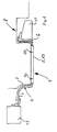
- the fuel line system 1 shows a fuel line system 1, that of at least one supply line 2 and at least a return line 3 consists.
- the fuel line system 1 is in the embodiment shown in FIG divided into three sections 4, 5, 6. Of the Front and rear section 4 and 6 is usually formed as a tube, for example, a Elastomer hose may be.
- the middle section 5 is used in particular for cooling in the return line 3 contained fuel.
- the middle section 5 is at the bottom or bottom plate 7 of the body 8 of a motor vehicle, for example via Clips 9 and 10 attached acoustically decoupled.
- the Fuel line system 1 promotes the fuel from a Fuel tank 11 via the flow line 2 to an engine 12.
- the engine 12 is not consumed Fuel is very hot and gets over the return line 3 returned to the fuel tank 11.
- the middle one Section 5 is with a thermally conductive surface enlargement 13 provided. embodiments Such surface enlargement 13 are in the Fig. 2 to 5 shown.
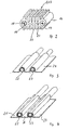
- Fig. 2 is a perspective sectional view a surface enlargement 13 is shown, which is designed as an extruded tube profile 16.
- the Extrusion tube profile 16 has two lines 17 and 18th on, in which the fuel forward or backward.
- the Return line 18 is a second line 19 with a smaller cross section in contact with the surface enlargement 13 arranged.
- the Surface enlargement 13 of Fig. 3 consists of Longitudinal ribs 20, which are integral to a transverse web 21st are formed.
- the pros and Return lines 17, 18, 19 are considered a common profile produced. From Fig. 2 is with respect to the Leads 18 and 19 also show that the surface enlargement 13 by a cross-sectional increase of Normal line 19 with respect to the enlarged line 18 can take place. In addition to the surface enlargement 13 has the cross-sectional increase the further effect that the fuel in the fuel line at a larger cross section slower through the pipe flows, so that the residence time of the fuel in the cooling section 5 is increased and thus more Heat can be radiated to the environment.
- the Connections from the extruded tube 16 to the profile Front and rear sections 4 and 5 are over Pressed or screwed nozzles.
- FIGS. 3 and 4 show an embodiment of the cooling section 5, in which the heat-conductive lines 22 and 23 are surrounded by a heat-conducting plate 24 or a plurality of heat-conducting plates 25, 26, 27.
- the nickelleitbleche 24; 25, 26, 27 are simultaneously used as c w value coverage of the underside 7 of the body 8 of a motor vehicle.
- the heat conducting plates 24; 25, 26, 27 and arranged therein lines 22, 23 acoustically decoupled fixed to the body 8.
Landscapes
- Engineering & Computer Science (AREA)
- Physics & Mathematics (AREA)
- Mechanical Engineering (AREA)
- General Engineering & Computer Science (AREA)
- Thermal Sciences (AREA)
- Geometry (AREA)
- Chemical & Material Sciences (AREA)
- Combustion & Propulsion (AREA)
- Cooling, Air Intake And Gas Exhaust, And Fuel Tank Arrangements In Propulsion Units (AREA)
Description
Die Erfindung betrifft ein Kraftfahrzeug gemäß dem Oberbegriff des Anspruchs 1.The invention relates to a motor vehicle according to the preamble of claim 1.
Aus der WO-A-94/23257 ist bereits ein Kraftfahrzeug mit einem Motor und einem Kraftstoffbehälter bekannt, bei dem zwischen dem Motor und dem Kraftstoffbehälter ein Kraftstoffleitungssystem angeordnet ist. Das Kraftstoffleitungssystem weist eine Vorlauf- und eine Rücklaufleitung auf. Ein Abschnitt des bekannten Kraftstoffleitungssystems ist mit mindestens einem Abschnitt einer wärmeleitfähigen Oberflächenvergrößerung zur Luftkühlung des in den Kraftstoffleitungen strömenden Kraftstoffes versehen. Die bekannte wärmeleitfähige Oberflächenvergrößerung besteht aus Kühlrippen, die aus einem Leichtmetall hergestellt sind.From WO-A-94/23257 is already a motor vehicle with an engine and a fuel tank known in which between the engine and the fuel tank arranged a fuel line system is. The fuel line system has a flow and a return line on. A section of the known Fuel line system is with at least one section a thermally conductive surface enlargement for cooling the air flowing in the fuel lines Fuel provided. The known thermally conductive Surface enlargement consists of cooling fins, which are made of a light metal.
Aus der DE-OS 37 04 215 ist bereits ein Strangpreßprofilrohr für Wärmeaustauscher bekannt, das aus mindestens zwei Profilhälften zusammengesetzt ist, die entlang zweier äußerer Längsränder dicht miteinander verbunden sind. Das Strangpreßprofilrohr kann innen und/oder außen mit die Wärmeaustauschfläche vergrößernden Elementen versehen sein. Diese Elemente können z. B. aus Längsrippen oder aus vorzugsweise in Längsreihen aufeinanderfolgenden einzelnen Zungen, Flügeln oder Vorsprüngen bestehen, die durch Einschnitte in Längsrippen und durch Abbiegen, Drehen oder dergleichen gebildet werden. Ferner können an dem Strangpreßprofilrohr Haltemittel vorgesehen sein, die zur Befestigung von die Wärmeaustauschfläche vergrößernden Elementen, z. B. zickzackförmigen Lamellen, dienen und die gleichzeitig eine gute Wärmeleitung vom Rohr zur Lamelle gewährleisten. Das Strangpreßprofilrohr ist vor allem für Wärmeaustauscher, z. B. für Kühler von Kraftfahrzeugen, bestimmt. Bei diesen Wärmetauschern wird das Kühlwasser des Motors durch den Fahrtwind und/oder durch einen Ventilator abgekühlt.From DE-OS 37 04 215 is already a Extruded profile tube known for heat exchangers, composed of at least two profile halves is dense along two outer longitudinal edges connected to each other. The extruded profile tube can be inside and / or outside with the heat exchange surface be provided magnifying elements. These Elements can be z. B. from longitudinal ribs or preferably in longitudinal rows successive individual Tongues, wings or protrusions exist, by cuts in longitudinal ribs and by turning, Turning or the like can be formed. Further can be provided on the extrusion profile tube holding means be used for fixing the heat exchange surface magnifying elements, z. B. zigzag Slats, serve and at the same time a good Ensure heat conduction from the pipe to the lamella. The extruded profile tube is primarily for heat exchangers, z. B. for radiators of motor vehicles determined. In these heat exchangers, the cooling water of the engine by the airstream and / or by a Fan cooled.
Bei zukünftigen Motoren kann es aufgrund des Einsatzes neuer Techniken zu einer massiven Erhöhung der Kraftstofftemperatur kommen, die beispielsweise 50 % über der bislang maximalen Kraftstofftemperatur liegt. Bei den dann erreichten Kraftstofftemperaturen, die überwiegend oberhalb von 100 °C liegen, kommt es jedoch zu Problemen mit Kraftstoffbehältern aus Kunststoff und/oder den im Kraftstoffbehälter befindlichen Zusatzeinrichtungen, die Kunststoff-Bauteile enthalten. Bisher verwendete Systeme zur Kraftstoffkühlung sind jedoch aufwendig und teuer.For future engines it may be due to the Use of new techniques for a massive increase the fuel temperature come, for example 50% above the maximum fuel temperature so far lies. At the then reached fuel temperatures, which are predominantly above 100 ° C, However, there are problems with fuel tanks made of plastic and / or located in the fuel tank Additional equipment, the plastic components contain. Previously used systems for fuel cooling However, they are expensive and expensive.
Aufgabe der Erfindung ist es, ein Kraftfahrzeug zu schaffen, bei dem in einfacher Weise eine Kraftstoffkühlung möglich ist.The object of the invention is a motor vehicle to provide, in a simple way, a fuel cooling is possible.
Diese Aufgabe wird durch die Merkmale des Anspruchs 1 gelöst.This task is characterized by the characteristics of Claim 1 solved.
Bei dem erfindungsgemäßen Kraftfahrzeug erfolgt eine Luftkühlung des in den Kraftstoffleitungen befindlichen Kraftstoffes dadurch, daß als gemeinsame Oberflächenvergrößerung für die Vorlauf- und die Rücklaufleitung ein Wärmeleitblech oder eine als Strangpress profil ausgebildete Querschnittserhöhung der Leitung vorgesehen ist, die nur abschnittsweise ausgebildet ist. Die wärmeleitfähige Oberflächenvergrößerung ist an der Außenoberfläche der Karosserie eines Kraftfahrzeuges, insbesondere am Bodenblech, angeordnet.In the motor vehicle according to the invention An air cooling takes place in the fuel lines located fuel in that as a common surface enlargement for the flow line and the return line a Wärmeleitblech or a profile formed as an extrusion cross-sectional increase the line is provided, which only partially is trained. The thermally conductive surface enlargement is on the outer surface of the body of a motor vehicle, in particular on the floor panel, arranged.
Die Oberflächenvergrößerung erfolgt in einer Ausführungsform durch die Ausbildung von Zusatzflächen, d. h. von Bauteilen wie Rippen, die von der Kraftstoffleitung abstehen und/oder von Wärmeleitblechen, die mit der Kraftstoffleitung verbunden sind. In einer weiteren Ausführungsform kann die Oberflächenvergrößerung dadurch erfolgen, daß die Kraftstoffleitung einen größeren Querschnitt aufweist. Weitere Ausführungsformen ergeben sich durch Kombinationen der vorgenannten Möglichkeiten.The surface enlargement takes place in one Embodiment by the formation of additional surfaces, d. H. of components such as ribs coming from the fuel line stand out and / or of Wärmeleitblechen, which are connected to the fuel line. In another Embodiment may be the surface enlargement take place in that the fuel line a larger Cross section has. Further embodiments arise by combinations of the aforementioned Options.
Die erfindungsgemäße Oberflächenvergrößerung ist so bemessen, daß die Temperatur des über die Rücklaufleitung zurückfließenden Kraftstoffes so weit abgekühlt ist, daß die zulässige Dauerbetriebstemperatur des Kraftstoffbehälters und/oder dessen Einbaueinheiten nicht überschritten wird.The surface enlargement according to the invention is sized so that the temperature of the above Return line returning fuel so far is cooled, that the permissible continuous operating temperature of the fuel tank and / or its installation units is not exceeded.
Die abschnittsweise Ausbildung einer wärmeleitfähigen Oberflächenvergrößerung in Form von Strangpreßprofilrohren hat den Vorteil, daß kostengünstige Meterware verwendet werden kann. Bei der Verwendung von Wärmeleitblechen ist eine Gestaltung möglich, die zu einer Verbesserung des cw-Wertes führt.The sectional formation of a thermally conductive surface enlargement in the form of extruded profile tubes has the advantage that inexpensive meterware can be used. When using Wärmeleitblechen a design is possible, which leads to an improvement of the c w value.
In einer anderen Ausführungsform ist es möglich, daß innerhalb der Kraftstoffleitung eine Leitung mit einem kleineren Querschnitt ausgebildet ist. Die Umschaltung von der Leitung mit dem größeren Querschnitt auf die Leitung mit dem kleineren Querschnitt und umgekehrt erfolgt beispielsweise über ein Thermostat-Ventil.In another embodiment is it possible for that inside the fuel line a pipe with a smaller cross-section is trained. Switching from the line with the larger cross-section on the pipe with the smaller Cross-section and vice versa, for example via a thermostatic valve.
Aus akustischen Gründen ist erfindungsgemäß das Kraftstoffleitungssystem durch eine entsprechende Befestigungsart akustisch von der Karosserie des Kraftfahrzeuges entkoppelt.For acoustic reasons is according to the invention the fuel line system by a corresponding Mounting type acoustic from the body of the motor vehicle decoupled.
Ausführungsformen der Erfindung werden nachstehend anhand der Zeichnungen beispielshalber beschrieben. Dabei zeigen:
- Fig. 1
- eine Prinzipdarstellung von der Seite eines Kraftstoffleitungssystems, das eine wärmeleitfähige Oberflächenvergrößerung aufweist, die an der Unterseite einer Karosserie eines Kraftfahrzeuges befestigt ist,
- Fig. 2
- eine perspektivische Schnittansicht einer Strangpreßprofitrohneitung mit einer Vorlaufleitung und zwei unterschiedlich großen Rücklaufleitungen,
- Fig. 3
- eine perspektivische Schnittansicht einer Vorlauf- und einer Rücklaufleitung. die in einem Wärmeleitblech befestigt sind und
- Fig. 4
- eine perspektivische Schnittansicht einer Vorlauf- und einer Rücklaufleitung, an denen jeweils Abschnitte eines Wärmeleitbleches angeordnet sind.
- Fig. 1
- a schematic representation of the side of a fuel rail system having a thermally conductive surface enlargement, which is attached to the underside of a body of a motor vehicle,
- Fig. 2
- 3 a perspective sectional view of an extruded-tube line with a feed line and two return lines of different sizes,
- Fig. 3
- a sectional perspective view of a flow and a return line. which are mounted in a Wärmeleitblech and
- Fig. 4
- a perspective sectional view of a flow and a return line to which portions of a Wärmeleitbleches are respectively arranged.
Die Fig. 1 zeigt ein Kraftstoffleitungssystem 1,
das aus mindestens einer Vorlaufleitung 2 und mindestens
einer Rücklaufleitung 3 besteht. Das Kraftstoffleitungssystem
1 ist in der in der Fig. 1 dargestellten Ausführungsform
in drei Abschnitte 4, 5, 6 unterteilt. Der
vordere und hintere Abschnitt 4 und 6 ist in der Regel
als ein Schlauch ausgebildet, der beispielsweise ein
Elastomerschlauch sein kann. Der mittlere Abschnitt 5
dient zur Kühlung insbesondere des in der Rücklaufleitung
3 enthaltenen Kraftstoffes. Der mittlere Abschnitt
5 ist an der Unterseite bzw. dem Bodenblech 7 der Karosserie
8 eines Kraftfahrzeuges beispielsweise über
Klipse 9 und 10 akustisch entkoppelt befestigt. Das
Kraftstoffleitungssystem 1 fördert den Kraftstoff aus einem
Kraftstoffbehälter 11 über die Vorlaufleitung 2 zu
einem Motor 12. Der nicht vom Motor 12 verbrauchte
Kraftstoff ist sehr heiß und wird über die Rücklaufleitung
3 zum Kraftstoffbehälter 11 zurückbefördert. Der mittlere
Abschnitt 5 ist mit einer wärmeleitfähigen Oberflächenvergrößerung
13 versehen. Ausführungsformen
einer solchen Oberflächenvergrößerung 13 sind in den
Fig. 2 bis 5 dargestellt.1 shows a fuel line system 1,
that of at least one supply line 2 and at least
a
In der Fig. 2 ist eine perspektivische Schnittansicht
einer Oberflächenvergrößerung 13 dargestellt,
die als ein Strangpreßrohrprofil 16 ausgebildet ist. Das
Strangpreßrohrprofil 16 weist zwei Leitungen 17 und 18
auf, in denen der Kraftstoff vor- oder zurückläuft. In der
Rücklaufleitung 18 ist eine zweite Leitung 19 mit einem
kleineren Querschnitt in Kontakt mit der Oberflächenvergrößerung
13 angeordnet. Durch die Leitungen 17,
19 strömt zunächst der kalte Kraftstoff, bis der Kraftstoff
seine Betriebstemperatur erreicht hat. Dann wird
über ein temperaturabhängiges
Ventil die Leitung 18 dazugeschaltet, wobei
der Kraftstoff dann durch beide Leitungen 18, 19
oder nur durch die größere Leitung 18 fließen kann. Die
Oberflächenvergrößerung 13 der Fig. 3 besteht aus
Längsrippen 20, die einstückig an einem Quersteg 21
ausgebildet sind.In Fig. 2 is a perspective sectional view
a surface enlargement 13 is shown,
which is designed as an
Die Vor- und
Rücklaufleitungen 17, 18, 19 sind als ein gemeinsames Profil
hergestellt. Aus der Fig. 2 geht in bezug auf die
Leitungen 18 und 19 ferner hervor, daß die Oberflächenvergrößerung
13 durch eine Querschnittserhöhung der
Normalleitung 19 in bezug auf die vergrößerte Leitung
18 erfolgen kann. Neben der Oberflächenvergrößerung
13 hat die Querschnittserhöhung den weiteren Effekt,
daß der in der Kraftstoffleitung befindliche Kraftstoff bei
einem größeren Querschnitt langsamer durch die Leitung
fließt, so daß die Verweildauer des Kraftstoffes in
dem Kühlungsabschnitt 5 erhöht ist und somit mehr
Wärme an die Umgebung abgestrahlt werden kann. Die
Anschlüsse von dem Strangpreßrohrprofil 16 zu den
vorderen und hinteren Abschnitten 4 und 5 erfolgt über
eingepreßte bzw. eingeschraubte Stutzen.The pros and
Die Fig.3 und 4 zeigen eine Ausführungsform
des Kühlungsabschnittes 5, bei dem die wärmeleitfähigen
Leitungen 22 und 23 von einem Wärmeleitblech 24
oder mehreren Wärmeleitblechen 25, 26, 27 umgeben
sind. Die Wärmeleitbleche 24; 25, 26, 27 sind gleichzeitig
als cw-Wert-Abdeckung der Unterseite 7 der Karosserie
8 eines Kraftfahrzeuges einsetzbar. Wie bei dem
Strangpreßrohrprofil 16 sind auch die Wärmeleitbleche
24; 25, 26, 27 sowie die darin angeordneten Leitungen
22, 23 akustisch entkoppelt an der Karosserie 8 befestigt.FIGS. 3 and 4 show an embodiment of the cooling section 5, in which the heat-
Claims (3)
- A motor vehicle comprising a fuel piping system (1) containing at least one flow pipe (2) and at least one return pipe (3), each acoustically uncoupled and disposed on the outer surface of the body (8), especially on the floor panel (7), between an engine (12) and a fuel tank (11) belonging to the vehicle, wherein the fuel piping system (1) has at least one portion (5) comprising a heat-conducting enlarged surface (13) for cooling the fuel in air, wherein the enlarged surface (13) is so dimensioned, depending on values specific to the vehicle, that the fuel flowing back to the tank (11) is cooled to a permissible operating temperature, and wherein the heat-conducting enlarged surface (13) is made up of elements (20, 21) which project from the pipe (17, 18, 19) and are made of light metal, characterised in that a common enlarged surface for the flow pipe (2) and the return pipe (3) is provided in the form of a heat-conducting plate (24; 25, 26, 27) or an increased cross-section of the pipe in the form of an extruded profile (16).
- A fuel piping system according to claim 1,
characterised in that the pipe (18) serving as an enlarged surface (13) can be connected or disconnected in dependence on temperature. - A fuel piping system according to claim 1 or claim 2,
characterised in that the heat-conducting fin (24; 25, 26, 27) is made up of one or more metal plates.
Applications Claiming Priority (2)
| Application Number | Priority Date | Filing Date | Title |
|---|---|---|---|
| DE19619934A DE19619934A1 (en) | 1996-05-17 | 1996-05-17 | Fuel line system |
| DE19619934 | 1996-05-17 |
Publications (4)
| Publication Number | Publication Date |
|---|---|
| EP0807756A2 EP0807756A2 (en) | 1997-11-19 |
| EP0807756A3 EP0807756A3 (en) | 1998-04-01 |
| EP0807756B1 EP0807756B1 (en) | 2000-07-05 |
| EP0807756B2 true EP0807756B2 (en) | 2005-03-16 |
Family
ID=7794584
Family Applications (1)
| Application Number | Title | Priority Date | Filing Date |
|---|---|---|---|
| EP97104608A Expired - Lifetime EP0807756B2 (en) | 1996-05-17 | 1997-03-18 | Fuel conduit |
Country Status (2)
| Country | Link |
|---|---|
| EP (1) | EP0807756B2 (en) |
| DE (2) | DE19619934A1 (en) |
Families Citing this family (15)
| Publication number | Priority date | Publication date | Assignee | Title |
|---|---|---|---|---|
| DE19729857A1 (en) * | 1997-07-11 | 1999-01-14 | Volkswagen Ag | Motor vehicle with underbody heat exchanger |
| FR2774463A1 (en) * | 1998-01-30 | 1999-08-06 | Peugeot | Fuel cooling heat exchanger for motor vehicle internal combustion engine |
| FR2774462B1 (en) * | 1998-01-30 | 2000-04-14 | Peugeot | FLUID COOLER EXCHANGER |
| FR2774635B1 (en) * | 1998-02-09 | 2000-04-21 | Valeo Thermique Moteur Sa | FUEL COOLING DEVICE FOR A MOTOR VEHICLE ENGINE |
| DE19815167B4 (en) * | 1998-04-04 | 2006-11-23 | Adam Opel Ag | Fuel line system |
| DK79298A (en) | 1998-06-08 | 1999-12-09 | Norsk Hydro As | Profile of fuel cooling, a fuel line and a process for making them |
| DE19916530A1 (en) | 1999-04-13 | 2000-10-19 | Mannesmann Vdo Ag | Device for supplying an internal combustion engine of a motor vehicle with fuel |
| SE512730C2 (en) * | 1999-04-22 | 2000-05-08 | Scania Cv Ab | Fuel tank |
| US7011142B2 (en) | 2000-12-21 | 2006-03-14 | Dana Canada Corporation | Finned plate heat exchanger |
| CA2329408C (en) | 2000-12-21 | 2007-12-04 | Long Manufacturing Ltd. | Finned plate heat exchanger |
| ATE352017T1 (en) * | 2001-05-01 | 2007-02-15 | Beltran Julian Romero | PLATE-TUBE HEAT EXCHANGER |
| CA2392610C (en) | 2002-07-05 | 2010-11-02 | Long Manufacturing Ltd. | Baffled surface cooled heat exchanger |
| CA2425233C (en) | 2003-04-11 | 2011-11-15 | Dana Canada Corporation | Surface cooled finned plate heat exchanger |
| US7182125B2 (en) | 2003-11-28 | 2007-02-27 | Dana Canada Corporation | Low profile heat exchanger with notched turbulizer |
| DE102016123323B3 (en) * | 2016-12-02 | 2018-03-01 | Eberspächer Climate Control Systems GmbH & Co. KG | vehicle |
Family Cites Families (17)
| Publication number | Priority date | Publication date | Assignee | Title |
|---|---|---|---|---|
| US3294148A (en) * | 1966-12-27 | Fuel feeding system for internal combustion engines | ||
| US2969110A (en) * | 1959-03-12 | 1961-01-24 | Exxon Research Engineering Co | Fuel delivery system for automotive vehicles |
| FR1479486A (en) * | 1966-03-14 | 1967-05-05 | Special profile tube for the constitution of heat exchangers | |
| CH606958A5 (en) * | 1976-12-02 | 1978-11-30 | Pierre Chuard | Tube and plate heat exchanger unit |
| IT1156963B (en) * | 1978-04-17 | 1987-02-04 | Fiat Veicoli Ind | SYSTEM FOR FUEL SUPPLY TO AN INTERNAL COMBUSTION ENGINE |
| EP0038710A1 (en) * | 1980-04-23 | 1981-10-28 | Barry William Wilder | Petrol cooling arrangement for engines |
| DE3153101C2 (en) * | 1981-01-02 | 1985-09-26 | Daimler-Benz Ag, 7000 Stuttgart | Fuel cooler |
| JPS59155564A (en) * | 1983-02-24 | 1984-09-04 | Toyota Motor Corp | Fuel distributing pipe for fuel injection type engine |
| DE3704215C2 (en) * | 1987-02-11 | 1995-11-30 | Laengerer & Reich Kuehler | Extruded profile tube for heat exchangers |
| DE3735915A1 (en) * | 1987-10-23 | 1989-05-03 | Wieland Werke Ag | Heat exchanger |
| DE3740811A1 (en) * | 1987-12-02 | 1989-06-15 | Zdenek Struhovsky | Fuel cooler for an internal combustion engine |
| DE3800296A1 (en) * | 1988-01-08 | 1989-07-20 | Porsche Ag | COOLING DEVICE ON A MOTOR VEHICLE |
| DE3912534C2 (en) * | 1989-04-17 | 1994-07-14 | Hansa Metallwerke Ag | Gasoline cooler |
| JPH0343653A (en) * | 1989-07-08 | 1991-02-25 | Nippondenso Co Ltd | Fuel cooling device |
| JPH04132446U (en) * | 1991-05-29 | 1992-12-08 | 本田技研工業株式会社 | automotive gasoline cooling system |
| DE4141689C2 (en) * | 1991-12-18 | 1997-01-30 | Audi Ag | Device for holding a line on a wall of a motor vehicle |
| WO1994023257A1 (en) * | 1993-03-29 | 1994-10-13 | Melanesia International Trust Company Limited | Heat exchanger assembly |
-
1996
- 1996-05-17 DE DE19619934A patent/DE19619934A1/en not_active Withdrawn
-
1997
- 1997-03-18 EP EP97104608A patent/EP0807756B2/en not_active Expired - Lifetime
- 1997-03-18 DE DE59701962T patent/DE59701962D1/en not_active Expired - Lifetime
Also Published As
| Publication number | Publication date |
|---|---|
| EP0807756A3 (en) | 1998-04-01 |
| DE19619934A1 (en) | 1997-11-20 |
| EP0807756A2 (en) | 1997-11-19 |
| EP0807756B1 (en) | 2000-07-05 |
| DE59701962D1 (en) | 2000-08-10 |
Similar Documents
| Publication | Publication Date | Title |
|---|---|---|
| EP0807756B2 (en) | Fuel conduit | |
| DE69720347T3 (en) | Combined heat exchanger | |
| EP0818663B1 (en) | Heat exchanger,more particularly radiator | |
| DE19755095A1 (en) | Motor vehicle, especially passenger car | |
| DE102019205575A1 (en) | Device for cooling a vehicle battery | |
| EP0582835A1 (en) | Heat-exchanger | |
| EP0890810B1 (en) | Automotive vehicle with heat exchanger under the floor | |
| EP0214517B1 (en) | Heating circuit with a heat accumulator for motor vehicles | |
| DE69905862T2 (en) | HEAT EXCHANGER WITH BENDING TUBES | |
| DE4431107C1 (en) | Heat exchanger arrangement to heat motor vehicle cab, using engine waste heat | |
| DE4438093C1 (en) | Ventilation device for parts of motor vehicle engines | |
| DE2606507A1 (en) | AIR CONDITIONER | |
| EP1083072B1 (en) | Cooling system for a combustion engine | |
| EP1492990A2 (en) | Heat exchanger and cooling system | |
| DE102007008884A1 (en) | Radiator, particularly for heater or air conditioner for motor vehicles, has collecting tank, which is connected with inlet, outlet and fluid flowing piping system or ribbed system, which is formed at range | |
| DE1655069A1 (en) | Heat exchanger for heating and cooling vehicles | |
| DE102007027250B4 (en) | motor vehicle | |
| DE3611713C1 (en) | Radiator fan system in a motor vehicle | |
| DE102004049670B4 (en) | Fuel cooler, motor vehicle with such a fuel cooler | |
| AT397859B (en) | HEAT EXCHANGER | |
| DE20304501U1 (en) | Floor heating for park home or motor home has rectangular metal tubes between lower wooden barrier layer, metal plate, foam filling gaps, closed fluid circuit heated by radiator, pump | |
| DE102007024038A1 (en) | Heat exchanger has thermoelectric unit having two sides, where fluid line is thermally coupled to one of sides and another fluid line coupled to other side | |
| DE60309828T2 (en) | heating system | |
| DE10142512B4 (en) | Electric heating device for motor vehicles | |
| DE102022122407A1 (en) | Radiator arrangement with at least two heat exchangers and with vertical refrigerant lines in one of the heat exchangers, motor vehicle with radiator arrangement |
Legal Events
| Date | Code | Title | Description |
|---|---|---|---|
| PUAI | Public reference made under article 153(3) epc to a published international application that has entered the european phase |
Free format text: ORIGINAL CODE: 0009012 |
|
| AK | Designated contracting states |
Kind code of ref document: A2 Designated state(s): DE FR GB IT |
|
| PUAL | Search report despatched |
Free format text: ORIGINAL CODE: 0009013 |
|
| AK | Designated contracting states |
Kind code of ref document: A3 Designated state(s): DE FR GB IT |
|
| 17P | Request for examination filed |
Effective date: 19980915 |
|
| 17Q | First examination report despatched |
Effective date: 19990120 |
|
| GRAG | Despatch of communication of intention to grant |
Free format text: ORIGINAL CODE: EPIDOS AGRA |
|
| GRAG | Despatch of communication of intention to grant |
Free format text: ORIGINAL CODE: EPIDOS AGRA |
|
| GRAH | Despatch of communication of intention to grant a patent |
Free format text: ORIGINAL CODE: EPIDOS IGRA |
|
| RTI1 | Title (correction) |
Free format text: FUEL CONDUIT |
|
| 17Q | First examination report despatched |
Effective date: 19990120 |
|
| RIN1 | Information on inventor provided before grant (corrected) |
Inventor name: CHRISTIAN, TREML Inventor name: GUENTHER, TUSCHL |
|
| GRAH | Despatch of communication of intention to grant a patent |
Free format text: ORIGINAL CODE: EPIDOS IGRA |
|
| GRAA | (expected) grant |
Free format text: ORIGINAL CODE: 0009210 |
|
| AK | Designated contracting states |
Kind code of ref document: B1 Designated state(s): DE FR GB IT |
|
| GBT | Gb: translation of ep patent filed (gb section 77(6)(a)/1977) |
Effective date: 20000705 |
|
| REF | Corresponds to: |
Ref document number: 59701962 Country of ref document: DE Date of ref document: 20000810 |
|
| ET | Fr: translation filed | ||
| ITF | It: translation for a ep patent filed | ||
| PLBQ | Unpublished change to opponent data |
Free format text: ORIGINAL CODE: EPIDOS OPPO |
|
| PLBI | Opposition filed |
Free format text: ORIGINAL CODE: 0009260 |
|
| 26 | Opposition filed |
Opponent name: NORSK HYDRO ASA Effective date: 20010402 Opponent name: AUDI AG Effective date: 20010331 |
|
| PLBF | Reply of patent proprietor to notice(s) of opposition |
Free format text: ORIGINAL CODE: EPIDOS OBSO |
|
| PLBF | Reply of patent proprietor to notice(s) of opposition |
Free format text: ORIGINAL CODE: EPIDOS OBSO |
|
| REG | Reference to a national code |
Ref country code: GB Ref legal event code: IF02 |
|
| PLBC | Reply to examination report in opposition received |
Free format text: ORIGINAL CODE: EPIDOSNORE3 |
|
| PUAH | Patent maintained in amended form |
Free format text: ORIGINAL CODE: 0009272 |
|
| STAA | Information on the status of an ep patent application or granted ep patent |
Free format text: STATUS: PATENT MAINTAINED AS AMENDED |
|
| 27A | Patent maintained in amended form |
Effective date: 20050316 |
|
| AK | Designated contracting states |
Kind code of ref document: B2 Designated state(s): DE FR GB IT |
|
| GBTA | Gb: translation of amended ep patent filed (gb section 77(6)(b)/1977) | ||
| ET3 | Fr: translation filed ** decision concerning opposition | ||
| PLAB | Opposition data, opponent's data or that of the opponent's representative modified |
Free format text: ORIGINAL CODE: 0009299OPPO |
|
| PGFP | Annual fee paid to national office [announced via postgrant information from national office to epo] |
Ref country code: DE Payment date: 20140319 Year of fee payment: 18 |
|
| PGFP | Annual fee paid to national office [announced via postgrant information from national office to epo] |
Ref country code: IT Payment date: 20140327 Year of fee payment: 18 |
|
| PGFP | Annual fee paid to national office [announced via postgrant information from national office to epo] |
Ref country code: GB Payment date: 20140327 Year of fee payment: 18 |
|
| PGFP | Annual fee paid to national office [announced via postgrant information from national office to epo] |
Ref country code: FR Payment date: 20140327 Year of fee payment: 18 |
|
| REG | Reference to a national code |
Ref country code: DE Ref legal event code: R119 Ref document number: 59701962 Country of ref document: DE |
|
| GBPC | Gb: european patent ceased through non-payment of renewal fee |
Effective date: 20150318 |
|
| PG25 | Lapsed in a contracting state [announced via postgrant information from national office to epo] |
Ref country code: IT Free format text: LAPSE BECAUSE OF NON-PAYMENT OF DUE FEES Effective date: 20150318 |
|
| REG | Reference to a national code |
Ref country code: FR Ref legal event code: ST Effective date: 20151130 |
|
| PG25 | Lapsed in a contracting state [announced via postgrant information from national office to epo] |
Ref country code: GB Free format text: LAPSE BECAUSE OF NON-PAYMENT OF DUE FEES Effective date: 20150318 Ref country code: DE Free format text: LAPSE BECAUSE OF NON-PAYMENT OF DUE FEES Effective date: 20151001 |
|
| PG25 | Lapsed in a contracting state [announced via postgrant information from national office to epo] |
Ref country code: FR Free format text: LAPSE BECAUSE OF NON-PAYMENT OF DUE FEES Effective date: 20150331 |