EP0807749A2 - Dispositif d'échappement pour véhicules automobiles, ainsi que un véhicule automobile - Google Patents
Dispositif d'échappement pour véhicules automobiles, ainsi que un véhicule automobile Download PDFInfo
- Publication number
- EP0807749A2 EP0807749A2 EP97810288A EP97810288A EP0807749A2 EP 0807749 A2 EP0807749 A2 EP 0807749A2 EP 97810288 A EP97810288 A EP 97810288A EP 97810288 A EP97810288 A EP 97810288A EP 0807749 A2 EP0807749 A2 EP 0807749A2
- Authority
- EP
- European Patent Office
- Prior art keywords
- exhaust
- housing
- exhaust system
- line element
- vehicle body
- Prior art date
- Legal status (The legal status is an assumption and is not a legal conclusion. Google has not performed a legal analysis and makes no representation as to the accuracy of the status listed.)
- Granted
Links
Images


Classifications
-
- F—MECHANICAL ENGINEERING; LIGHTING; HEATING; WEAPONS; BLASTING
- F01—MACHINES OR ENGINES IN GENERAL; ENGINE PLANTS IN GENERAL; STEAM ENGINES
- F01N—GAS-FLOW SILENCERS OR EXHAUST APPARATUS FOR MACHINES OR ENGINES IN GENERAL; GAS-FLOW SILENCERS OR EXHAUST APPARATUS FOR INTERNAL-COMBUSTION ENGINES
- F01N13/00—Exhaust or silencing apparatus characterised by constructional features
- F01N13/18—Construction facilitating manufacture, assembly, or disassembly
- F01N13/1805—Fixing exhaust manifolds, exhaust pipes or pipe sections to each other, to engine or to vehicle body
- F01N13/1811—Fixing exhaust manifolds, exhaust pipes or pipe sections to each other, to engine or to vehicle body with means permitting relative movement, e.g. compensation of thermal expansion or vibration
- F01N13/1822—Fixing exhaust manifolds, exhaust pipes or pipe sections to each other, to engine or to vehicle body with means permitting relative movement, e.g. compensation of thermal expansion or vibration for fixing exhaust pipes or devices to vehicle body
-
- F—MECHANICAL ENGINEERING; LIGHTING; HEATING; WEAPONS; BLASTING
- F01—MACHINES OR ENGINES IN GENERAL; ENGINE PLANTS IN GENERAL; STEAM ENGINES
- F01N—GAS-FLOW SILENCERS OR EXHAUST APPARATUS FOR MACHINES OR ENGINES IN GENERAL; GAS-FLOW SILENCERS OR EXHAUST APPARATUS FOR INTERNAL-COMBUSTION ENGINES
- F01N13/00—Exhaust or silencing apparatus characterised by constructional features
- F01N13/007—Apparatus used as intake or exhaust silencer
-
- B—PERFORMING OPERATIONS; TRANSPORTING
- B60—VEHICLES IN GENERAL
- B60K—ARRANGEMENT OR MOUNTING OF PROPULSION UNITS OR OF TRANSMISSIONS IN VEHICLES; ARRANGEMENT OR MOUNTING OF PLURAL DIVERSE PRIME-MOVERS IN VEHICLES; AUXILIARY DRIVES FOR VEHICLES; INSTRUMENTATION OR DASHBOARDS FOR VEHICLES; ARRANGEMENTS IN CONNECTION WITH COOLING, AIR INTAKE, GAS EXHAUST OR FUEL SUPPLY OF PROPULSION UNITS IN VEHICLES
- B60K13/00—Arrangement in connection with combustion air intake or gas exhaust of propulsion units
- B60K13/04—Arrangement in connection with combustion air intake or gas exhaust of propulsion units concerning exhaust
-
- F—MECHANICAL ENGINEERING; LIGHTING; HEATING; WEAPONS; BLASTING
- F01—MACHINES OR ENGINES IN GENERAL; ENGINE PLANTS IN GENERAL; STEAM ENGINES
- F01N—GAS-FLOW SILENCERS OR EXHAUST APPARATUS FOR MACHINES OR ENGINES IN GENERAL; GAS-FLOW SILENCERS OR EXHAUST APPARATUS FOR INTERNAL-COMBUSTION ENGINES
- F01N13/00—Exhaust or silencing apparatus characterised by constructional features
- F01N13/009—Exhaust or silencing apparatus characterised by constructional features having two or more separate purifying devices arranged in series
-
- F—MECHANICAL ENGINEERING; LIGHTING; HEATING; WEAPONS; BLASTING
- F01—MACHINES OR ENGINES IN GENERAL; ENGINE PLANTS IN GENERAL; STEAM ENGINES
- F01N—GAS-FLOW SILENCERS OR EXHAUST APPARATUS FOR MACHINES OR ENGINES IN GENERAL; GAS-FLOW SILENCERS OR EXHAUST APPARATUS FOR INTERNAL-COMBUSTION ENGINES
- F01N13/00—Exhaust or silencing apparatus characterised by constructional features
- F01N13/18—Construction facilitating manufacture, assembly, or disassembly
- F01N13/1805—Fixing exhaust manifolds, exhaust pipes or pipe sections to each other, to engine or to vehicle body
- F01N13/1811—Fixing exhaust manifolds, exhaust pipes or pipe sections to each other, to engine or to vehicle body with means permitting relative movement, e.g. compensation of thermal expansion or vibration
- F01N13/1816—Fixing exhaust manifolds, exhaust pipes or pipe sections to each other, to engine or to vehicle body with means permitting relative movement, e.g. compensation of thermal expansion or vibration the pipe sections being joined together by flexible tubular elements only, e.g. using bellows or strip-wound pipes
-
- F—MECHANICAL ENGINEERING; LIGHTING; HEATING; WEAPONS; BLASTING
- F01—MACHINES OR ENGINES IN GENERAL; ENGINE PLANTS IN GENERAL; STEAM ENGINES
- F01N—GAS-FLOW SILENCERS OR EXHAUST APPARATUS FOR MACHINES OR ENGINES IN GENERAL; GAS-FLOW SILENCERS OR EXHAUST APPARATUS FOR INTERNAL-COMBUSTION ENGINES
- F01N3/00—Exhaust or silencing apparatus having means for purifying, rendering innocuous, or otherwise treating exhaust
- F01N3/08—Exhaust or silencing apparatus having means for purifying, rendering innocuous, or otherwise treating exhaust for rendering innocuous
- F01N3/10—Exhaust or silencing apparatus having means for purifying, rendering innocuous, or otherwise treating exhaust for rendering innocuous by thermal or catalytic conversion of noxious components of exhaust
- F01N3/24—Exhaust or silencing apparatus having means for purifying, rendering innocuous, or otherwise treating exhaust for rendering innocuous by thermal or catalytic conversion of noxious components of exhaust characterised by constructional aspects of converting apparatus
- F01N3/28—Construction of catalytic reactors
- F01N3/2882—Catalytic reactors combined or associated with other devices, e.g. exhaust silencers or other exhaust purification devices
- F01N3/2885—Catalytic reactors combined or associated with other devices, e.g. exhaust silencers or other exhaust purification devices with exhaust silencers in a single housing
-
- F—MECHANICAL ENGINEERING; LIGHTING; HEATING; WEAPONS; BLASTING
- F01—MACHINES OR ENGINES IN GENERAL; ENGINE PLANTS IN GENERAL; STEAM ENGINES
- F01N—GAS-FLOW SILENCERS OR EXHAUST APPARATUS FOR MACHINES OR ENGINES IN GENERAL; GAS-FLOW SILENCERS OR EXHAUST APPARATUS FOR INTERNAL-COMBUSTION ENGINES
- F01N1/00—Silencing apparatus characterised by method of silencing
- F01N1/24—Silencing apparatus characterised by method of silencing by using sound-absorbing materials
-
- F—MECHANICAL ENGINEERING; LIGHTING; HEATING; WEAPONS; BLASTING
- F01—MACHINES OR ENGINES IN GENERAL; ENGINE PLANTS IN GENERAL; STEAM ENGINES
- F01N—GAS-FLOW SILENCERS OR EXHAUST APPARATUS FOR MACHINES OR ENGINES IN GENERAL; GAS-FLOW SILENCERS OR EXHAUST APPARATUS FOR INTERNAL-COMBUSTION ENGINES
- F01N13/00—Exhaust or silencing apparatus characterised by constructional features
- F01N13/02—Exhaust or silencing apparatus characterised by constructional features having two or more separate silencers in series
-
- F—MECHANICAL ENGINEERING; LIGHTING; HEATING; WEAPONS; BLASTING
- F01—MACHINES OR ENGINES IN GENERAL; ENGINE PLANTS IN GENERAL; STEAM ENGINES
- F01N—GAS-FLOW SILENCERS OR EXHAUST APPARATUS FOR MACHINES OR ENGINES IN GENERAL; GAS-FLOW SILENCERS OR EXHAUST APPARATUS FOR INTERNAL-COMBUSTION ENGINES
- F01N13/00—Exhaust or silencing apparatus characterised by constructional features
- F01N13/14—Exhaust or silencing apparatus characterised by constructional features having thermal insulation
-
- F—MECHANICAL ENGINEERING; LIGHTING; HEATING; WEAPONS; BLASTING
- F01—MACHINES OR ENGINES IN GENERAL; ENGINE PLANTS IN GENERAL; STEAM ENGINES
- F01N—GAS-FLOW SILENCERS OR EXHAUST APPARATUS FOR MACHINES OR ENGINES IN GENERAL; GAS-FLOW SILENCERS OR EXHAUST APPARATUS FOR INTERNAL-COMBUSTION ENGINES
- F01N2230/00—Combination of silencers and other devices
-
- F—MECHANICAL ENGINEERING; LIGHTING; HEATING; WEAPONS; BLASTING
- F01—MACHINES OR ENGINES IN GENERAL; ENGINE PLANTS IN GENERAL; STEAM ENGINES
- F01N—GAS-FLOW SILENCERS OR EXHAUST APPARATUS FOR MACHINES OR ENGINES IN GENERAL; GAS-FLOW SILENCERS OR EXHAUST APPARATUS FOR INTERNAL-COMBUSTION ENGINES
- F01N2250/00—Combinations of different methods of purification
- F01N2250/02—Combinations of different methods of purification filtering and catalytic conversion
-
- F—MECHANICAL ENGINEERING; LIGHTING; HEATING; WEAPONS; BLASTING
- F01—MACHINES OR ENGINES IN GENERAL; ENGINE PLANTS IN GENERAL; STEAM ENGINES
- F01N—GAS-FLOW SILENCERS OR EXHAUST APPARATUS FOR MACHINES OR ENGINES IN GENERAL; GAS-FLOW SILENCERS OR EXHAUST APPARATUS FOR INTERNAL-COMBUSTION ENGINES
- F01N2260/00—Exhaust treating devices having provisions not otherwise provided for
- F01N2260/20—Exhaust treating devices having provisions not otherwise provided for for heat or sound protection, e.g. using a shield or specially shaped outer surface of exhaust device
-
- F—MECHANICAL ENGINEERING; LIGHTING; HEATING; WEAPONS; BLASTING
- F01—MACHINES OR ENGINES IN GENERAL; ENGINE PLANTS IN GENERAL; STEAM ENGINES
- F01N—GAS-FLOW SILENCERS OR EXHAUST APPARATUS FOR MACHINES OR ENGINES IN GENERAL; GAS-FLOW SILENCERS OR EXHAUST APPARATUS FOR INTERNAL-COMBUSTION ENGINES
- F01N2310/00—Selection of sound absorbing or insulating material
- F01N2310/02—Mineral wool, e.g. glass wool, rock wool, asbestos or the like
-
- F—MECHANICAL ENGINEERING; LIGHTING; HEATING; WEAPONS; BLASTING
- F01—MACHINES OR ENGINES IN GENERAL; ENGINE PLANTS IN GENERAL; STEAM ENGINES
- F01N—GAS-FLOW SILENCERS OR EXHAUST APPARATUS FOR MACHINES OR ENGINES IN GENERAL; GAS-FLOW SILENCERS OR EXHAUST APPARATUS FOR INTERNAL-COMBUSTION ENGINES
- F01N2340/00—Dimensional characteristics of the exhaust system, e.g. length, diameter or volume of the exhaust apparatus; Spatial arrangements of exhaust apparatuses
-
- F—MECHANICAL ENGINEERING; LIGHTING; HEATING; WEAPONS; BLASTING
- F01—MACHINES OR ENGINES IN GENERAL; ENGINE PLANTS IN GENERAL; STEAM ENGINES
- F01N—GAS-FLOW SILENCERS OR EXHAUST APPARATUS FOR MACHINES OR ENGINES IN GENERAL; GAS-FLOW SILENCERS OR EXHAUST APPARATUS FOR INTERNAL-COMBUSTION ENGINES
- F01N2530/00—Selection of materials for tubes, chambers or housings
- F01N2530/22—Flexible elastomeric material
-
- Y—GENERAL TAGGING OF NEW TECHNOLOGICAL DEVELOPMENTS; GENERAL TAGGING OF CROSS-SECTIONAL TECHNOLOGIES SPANNING OVER SEVERAL SECTIONS OF THE IPC; TECHNICAL SUBJECTS COVERED BY FORMER USPC CROSS-REFERENCE ART COLLECTIONS [XRACs] AND DIGESTS
- Y02—TECHNOLOGIES OR APPLICATIONS FOR MITIGATION OR ADAPTATION AGAINST CLIMATE CHANGE
- Y02A—TECHNOLOGIES FOR ADAPTATION TO CLIMATE CHANGE
- Y02A50/00—TECHNOLOGIES FOR ADAPTATION TO CLIMATE CHANGE in human health protection, e.g. against extreme weather
- Y02A50/20—Air quality improvement or preservation, e.g. vehicle emission control or emission reduction by using catalytic converters
Definitions
- the invention relates to an exhaust system for a motor vehicle having a vehicle body and an internal combustion engine, with an exhaust which can be connected to the internal combustion engine and which has at least one deformable line element, at least one pipe arranged downstream thereof and at least one muffler arranged downstream of said line element, and with holding means for holding the exhaust on the vehicle body.
- the exhaust system is provided, for example, for a passenger car whose vehicle body has a frame and a vehicle floor. However, the exhaust system can possibly also be used for another motor vehicle - for example a truck or bus.
- the internal combustion engine can consist of a gasoline or diesel engine.
- vibrations ie vibrations
- the engine pulsates exhaust gas to the exhaust, which can also excite vibrations of the exhaust. Vibrations with different vibration modes can occur in the exhaust.
- the vibrations of the exhaust cause periodically and relatively quickly changing accelerations of the vibrating parts of the exhaust. Driving over holes and other bumps, cornering and accelerating and braking the vehicle also cause the exhaust to accelerate. These accelerations caused by driving usually change much more slowly than the accelerations caused by the vibrations.
- the exhaust is also heated by the exhaust gas during engine operation, with the exhaust gas temperature decreasing away from the engine along the flow path.
- the heating causes a temporary extension of the exhaust due to the thermal expansion of the rigid parts of the exhaust.
- the lengths of the exhausts are, for example, approximately 4 m and the changes in length caused by temperature changes, for example, approximately 0.5% to 1%, ie approximately 2 cm to 4 cm.
- the holding means also have elastic elements and allow a fairly free, limited movement of the exhaust at least in different directions.
- a deformable conduit element which has, for example, a bellows or a rubber ring.
- the known deformable line elements primarily serve as decoupling elements in order to decouple the muffler and other exhaust parts arranged downstream from them in terms of vibrations from the engine. Since the known exhausts and in particular their parts arranged downstream of the deformable line elements can move quite freely within certain limits, transverse vibrations with large amplitudes are frequently generated in the exhausts despite the deformable line elements. This is particularly the case if the exhausts have resonances in the area of the fundamental vibrations generated by the engine. The vibrations and other accelerations and forces acting on the exhaust exert a heavy load on the pipes, muffler housings and deformable pipe elements belonging to the exhaust. The pipes of an exhaust pipe therefore have a wall thickness of at least 1.5 mm in passenger cars.
- the silencers usually have housings with jackets and end walls, the wall thickness of which is also more than 1 mm and often at least 1.5 mm in passenger cars.
- the exhaust pipes and muffler housings of trucks usually have even greater wall thicknesses.
- the exhaust of the known exhaust systems is therefore heavy.
- a heat protection shield that increases the weight often has to be arranged between the or each silencer and the vehicle floor.
- the high weight of the known exhaust systems requires a lot of material for their manufacture, for example a lot of relatively expensive, stainless steel, and above all increases the fuel consumption when driving. Furthermore, despite the large wall thicknesses, breaks in the exhaust occur quite frequently.
- the mufflers of the known exhausts are normally deflected transversely to the general longitudinal direction of the exhaust, starting from their central and / or rest position, in various transverse directions up to at least 1 cm and often up to 2 cm or even more, they are additionally stressed in addition to the space they occupy, space for their transverse movements. This often has the disadvantage that the silencers cannot be dimensioned as large as would be desirable for good sound insulation.
- the invention has for its object to avoid disadvantages of the known exhaust systems and in particular to create an exhaust system that has a low weight in relation to the flow rate of the exhaust gas to be discharged through the exhaust system and in relation to the length and the characteristic cross-sectional dimensions of the exhaust is permanent.
- the invention further relates to a motor vehicle which, according to the invention, has the features of claim 23.
- the weight of an exhaust system according to the invention can be considerably reduced compared to the weight of known exhaust systems with similar passage cross-sectional areas, cross-sectional dimensions and lengths of the various exhaust parts.
- the weight of the exhaust part arranged downstream of the first elastically deformable line element in the exhaust gas flow direction can, for example, be reduced by approximately or more than 50% with otherwise approximately the same dimensioning.
- a layer of sound-absorbing and heat-insulating insulation material is present in the housing of the or each silencer between the casing of the housing and a hollow interior. Furthermore, sound-absorbing and heat-insulating material is preferably also present between each end wall and the hollow interior of the or each silencer.
- the exhaust has a catalytic converter arranged downstream of the first elastically deformable line element and / or below the vehicle floor, its housing can likewise have sound-absorbing and heat-insulating materials arranged in an analog manner.
- These insulation materials preferably consist of mineral fibers, for example basalt wool and / or other rock wool and / or possibly glass wool. Such a material has a high temperature resistance and a relatively low density.
- Such thermal insulation of the or at least one or each housing arranged under the vehicle floor makes it possible to keep the heat transfer to the vehicle floor low despite the thin-walled housing and to dispense with the attachment of a metallic heat shield to the vehicle floor, thereby additionally saving weight.
- the holding means are designed to hold the or at least the (first) housing following the exhaust in the exhaust gas flow direction after the first elastically deformable line element on the vehicle body such that this or each housing is held by the Vibrations generated by the internal combustion engine and by the accelerations and forces otherwise acting on the exhaust are deflected at most little at least in all directions approximately perpendicular to the longitudinal direction of the vehicle.
- Such a relatively rigid attachment results in at least resonances of Transversal vibration modes of the (first) housing arranged downstream of the (first) elastically deformable line element and thus practically all of the exhaust part arranged downstream of said line element are largely suppressed.
- the vibration amplitudes and other movements of the exhaust part mentioned caused by driving are greatly reduced.
- This in turn enables the pipes and housings arranged downstream of the (first) elastically deformable line element to be made thin-walled and light and still achieve a long service life for the exhaust.
- the reduction in the transverse deflection also enables the diameter or other cross-sectional dimensions of a silencer housing to be increased without the latter striking the vehicle floor or other parts of the vehicle body as a result of vibrations or other accelerations.
- Such an enlargement of a silencer housing in turn enables an improvement in sound absorption.
- the holding means preferably have at least one holder for the or each housing which is arranged downstream of at least the (first) elastically deformable line element and is connected directly to the housing. It is then not necessary to hold the pipes themselves directly on the vehicle body. Since a muffler and / or catalytic converter with a housing normally has a larger mass and a greater weight per unit length than a pipe, holding means which engage directly on the or each housing contribute to stable fastening and low mechanical stress on the various parts of the exhaust .
- the motor vehicle 1 shown schematically in FIG. 1 consists of a passenger car and has a vehicle body 2. This has a self-supporting body 3, a vehicle floor 4 and a frame 5.
- the vehicle body 2 holds an internal combustion engine 6, front wheels 7, rear wheels 8 and an exhaust system designated as a whole by 11.
- the internal combustion engine 6 has a vibration-damping motor housing 6a fastened to the frame 5 with a plurality of exhaust gas outlets, each of which is assigned to a cylinder of the engine is.
- the main component of the exhaust system 11 is an exhaust pipe 12.
- This has an intake and collection device 13, a catalytic converter 14, a short pipe 15, a first elastically deformable line element 16, a longer, straight pipe 17, in the flow direction of the exhaust gas.
- the internal combustion engine 6 is located at the front end of the motor vehicle 1.
- the exhaust 12 generally runs approximately parallel to the longitudinal and driving direction of the motor vehicle 1 from the internal combustion engine 5 to the rear of the vehicle and is largely located below the vehicle floor 4 also holding means 27. These have four holders 28, 29, 30, 31 which connect the two silencers 19 and 23 near their ends to a rigid part of the vehicle body 2, namely to the vehicle floor 4.
- the intake and collection device 13 has an exhaust manifold which has a curved intake pipe for each exhaust gas outlet of the engine, the input of which is connected to one of the exhaust gas outlets of the engine housing.
- the device 13 furthermore has the common connection means connecting the outlets of the inlet pipes and an outlet 13a common to all inlet pipes.
- the inlet and collecting device 13 is, for example, completely rigid, but may possibly have at least one elastically deformable decoupling element with a bellows or the like, which connects one of the inlet pipes to the common outlet 13a.
- the common output 13a should be rigidly connected to at least one of the input pipes and to the motor housing 6a by the collective connection means.
- the catalytic converter 14 has a rigid housing with an inlet, which is rigidly connected to the common outlet 13a of the inlet and collection device 13.
- the tubes 15, 17, 20, 22, 24 are rigid.
- the inlet and collecting device 13, the housing of the catalytic converter 14 and the pipes 15, 17, 20, 22 and 24 consist of metallic materials, for example stainless steel.
- the device 13, the housing of the catalyst 14 and the tube 15 are tightly connected to one another, namely welded.
- the three elastically deformable line elements 16, 18, 21 are only shown schematically in FIG. 1 and have, for example, a metallic, namely made of stainless steel, flexible, bendable, extendable and shortenable bellows, the ends of which are tight and firm with the preceding ones and subsequent exhaust parts are connected, for example indirectly or directly welded.
- the line elements 16, 18, 21 can also have additional parts.
- the second elastically deformable line element 18 is designed, for example, according to FIG. 2 and has as its main components a bellows 33, an inner sleeve 34 located within it, an outer sleeve 35 surrounding the bellows in cross section and serving as a protective jacket, and a connecting piece 36.
- the line element 18 also has an approximately U-shaped ring 37 in cross-section with a groove open to the outside and a deformable damping element 38 held therein. This is formed by a multilayer wire mesh formed into a ring with a full cross-section and protrudes on the outside out of the groove of ring 37.
- the aforementioned parts of the line element 18 consist of metallic materials, for example stainless steel.
- the bellows 33 has a cylindrical end section at both ends and is rigidly and tightly connected at its end on the left in FIG. 2 to the ends of the two sleeves 34, 35, namely welded. These ends of the bellows 33 and the Sleeves together form the first connection 39 - namely the input - of the line element 18. The end of the bellows located on the right in FIG.
- the line element 18 is generally rotationally symmetrical with respect to an axis 41.
- the first and third elastically deformable line elements 16 and 21 are, for example, of the same or similar design as the second elastically deformable line element 18.
- the line elements 16, 18, 21 can also be dimensioned and / or designed differently and changed in different ways.
- the inner sleeve 34 can be omitted, for example, to increase the flexibility of the bellows.
- the outer sleeve 35, the ring 37 and the damping member 37 can be replaced, for example, in particular in the case of the first line element 16 or in all line elements 16, 18, 21 by a flexible, stretchable and shortenable jacket formed from wires or metal strips.
- the first elastically deformable line element 16 serves in particular as a vibration damper and a decoupling element and is intended to decouple the parts of the exhaust 12 located downstream of the line element 16 with respect to the exhaust gas flow direction in terms of vibrations from the engine and, as far as possible, to prevent vibrations or vibrations generated by the engine during operation from the engine housing onto the exhaust parts located downstream of the line element 16 be transmitted.
- the second and third line elements 18 and 21 also serve for vibration decoupling.
- the first and the second line elements 16 and 18 are also intended to decouple the exhaust parts located downstream of them from the motor housing in relation to other movements, ie movements not caused by vibrations, in particular tilting movements.
- the bellows of the three line elements 16, 18, 21 and, in particular, of the second and third line elements 18 and 21 can furthermore change their lengths under elastic deformations and, in particular, be shortened along their axes, starting from their idle states.
- the two sleeves 34, 35 are then shifted to the right against the connection 40, for example, starting from the illustrated idle state, which is assumed when the engine is not running.
- the distance between the two connections 39, 40 measured parallel to the axis 41 of the line element 18, ie the length of the line element can preferably be changed by at least 5 mm and for example up to approximately 10 mm or even somewhat more, ie reduced and / or starting from an idle state be enlarged.
- the first and the third line element 16 or 21 can preferably also change their length at least 5 mm and for example up to about 10 mm or even more, that is to say reduce and / or enlarge starting from a state of rest.
- the two conduit elements 16 and 18 can compensate for changes in length caused by temperature changes in the pipes 15 and 17 and other solid exhaust parts located upstream of the first silencer 19.
- the two line elements 16, 18 can together compensate for their axes and / or the longitudinal direction of the motor vehicle and / or the axis of the first silencer 19 parallel length and other dimensional changes that are up to at least 5 mm or at least 10 mm or even up to approximately or more than 20 mm.
- the third conduit element 21 can compensate for changes in length of the pipes 20, 22 located between the two silencers 19, 23.
- the third conduit element 21 can compensate for changes in length and / or other changes in dimension in the direction parallel to its axis and / or to the longitudinal direction of the motor vehicle and / or to the axes of the first muffler 19 and / or second muffler, which are up to at least 5 mm and for example up to at least 10 mm.
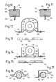
- the first muffler 19, which can be seen separately in FIGS. 3 and 4, has an elongated, sealed housing 45 which is generally rotationally symmetrical to a straight axis 46.
- the wall of the housing 45 has an essentially cylindrical casing 47 and two end walls 48 and 49 which face away from one another and are tightly and firmly connected to the casing.
- the two end walls are, for example, at least partially conical or curved to stiffen the housing.
- the housing 45 contains two gas permeable partitions 50, 51, each of which is near one of the end walls 48, 49 and consists of a substantially flat, annular, disc.
- the two intermediate walls 50, 51 are perforated at least in places and preferably also have at least one compact, unperforated area in order to achieve good rigidity.
- the silencer 19 has two tubes 53 coaxial with the axis 46 and 54.
- the tube 53 penetrates the end wall 48 and intermediate wall 50 located at the left end of the muffler.
- the other tube 54 penetrates the end wall 49 and the intermediate wall 51.
- the tubes 53, 54 are rigid and tight with the end wall 48 and 49, respectively connected.
- the intermediate walls 50, 51 are fixed and more or less tightly connected to the casing 47 and / or to the tube 53 or 54 and have, for example, flanges attached to the casing by spot welding connections.
- the outer end of the tube 53 forms the input connection of the silencer 19 and is connected to the line element 18.
- the outer end of the tube 54 forms the output connection of the silencer 19 and is connected to the line element 21 via the tube 20.
- Each tube 53, 54 has a gas permeable perforated portion 53a and 54a near its inner end, respectively. Between its perforated section 54a and its end serving as an outlet connection, the tube 54 also has a constriction serving as a throttle 54b.
- the inner ends of the two tubes 53, 54 are separated from one another in the axial direction by a space.
- the inner end of the tube 53 is more or less tightly closed or possibly open by being squeezed together.
- the inner end of the tube 54 is squeezed together and more or less sealed.
- the housing 45 contains a generally cylindrical inner jacket 55 between the two intermediate walls 50 and 51. This consists of two sleeve-shaped inner jacket parts, each of which is attached at one end to one of the intermediate walls 50, 51.
- the other end sections of the two inner jacket parts facing away from the intermediate walls enclose one another with at most little play and can be displaced relative to one another parallel to the axis 46.
- the two-part inner jacket 55 is gas-permeable and perforated for most of its length, but in the vicinity of its left-hand end it has a compact, ie hole-free section 55a, which encloses the axis 46, approximately over the length range of the perforated Pipe section 53a extends and protrudes a little beyond the latter at both ends, for example.
- the section of the tube 54 which is located inside the housing 45 is longer than half the length of the housing and is supported on its inner end by a few rod-shaped supports 56 on the inner jacket 55.
- the housing 45, the partition walls 50, 51, the two tubes 53, 54, the inner jacket 55 and the supports 56 are made of metallic materials, for example stainless steel.
- the annular spaces present between the end wall 48 and the intermediate wall 50 and between the end wall 49 and the intermediate wall 51 and enclosing the tube 53 or 54 are filled with a layer or filling of heat-insulating and sound-absorbing material 57 or 58.
- the intermediate space, which is annular in cross section and is located between the two intermediate walls 50, 51 and between the casing 47 of the housing and the inner casing 55, is also filled with a layer of heat-insulating and sound-absorbing material 59.
- the materials 57, 58, 59 consist, for example, of fibers of the type mentioned in the introduction.
- the second muffler 23, shown separately in FIGS. 5 and 6, has a housing 65 with a straight axis 66.
- the housing has a cylindrical jacket 67 and two end walls 68, 69.
- the housing contains two disk-shaped, at least partially gas-permeable, perforated intermediate walls 70 , 71.
- the silencer 23 has two tubes 73 and 74.
- the tube 73 penetrates the end wall 68 and the intermediate wall 70.
- the tube 74 penetrates the end wall 69 and the intermediate wall 71.
- the housing 65 of the second silencer 23 is shorter than the housing 45 of the first silencer 19, but has a larger diameter than the housing 45.
- the tubes 73, 74 are arranged parallel to the axis 66, but on different sides of it.
- the two tubes 73, 74 have sections located next to one another in the same longitudinal region of the housing 65.
- the outer end of the pipe 73 forms the input connection of the second silencer 23 and is connected to the pipe 22.
- the tube 73 is crimped together at its end located in the housing 65 and is more or less tightly closed or open and has a gas-permeable, perforated section 73a near this end.
- the tube 74 is open at its inner end and has no perforated section.
- the outer end of the tube 74 forms the output connection of the second silencer 23 and is connected to and / or forms the outlet tube 24.
- the second muffler 23 has an inner jacket 75 which, like the first muffler, consists of two inner jacket parts which project into one another and can be displaced relative to one another.
- the inner jacket 75 is largely gas-permeable and perforated, but has a compact, hole-free section 75a. This extends over a somewhat longer longitudinal region than the perforated section 73a of the tube 73, but does not completely enclose the axis 66, but only occupies a peripheral region of the inner jacket located in the vicinity of the tube 73.
- the two interstices present between the end walls 68, 69 and one of the gas-permeable intermediate walls 70 and 71 contain a material 77 and 78, respectively.
- the intermediate space existing between the housing jacket 67 and the inner jacket 75 contains a material 79.
- the materials 77, 78 , 79 are in turn heat-insulating and sound-absorbing and consist of mineral fibers.
- the interior 80 between the two partition walls 70 and 71, which is enclosed in cross section by the inner jacket 75, is apart from that Tubes 73, 74 hollow and free.
- the second silencer 23 is configured similarly to the first silencer 19.
- the holders 28, 29, 30, 31 shown schematically in FIG. 1 for fastening the two mufflers 19 and 23 can - depending on the design of the vehicle floor 3 - be differently designed and dimensioned or all the same.
- the two brackets 28, 29 used to fasten the first muffler 19 are, for example, of identical or similar design, are spaced apart from one another along the muffler axis 46 and are close to the two ends of the muffler 19, namely at its intermediate walls 50 or 51 attached to its coat.
- the holder 28 is designed, for example, according to FIGS. 7 and 8.
- a section of the vehicle floor 4 can also be seen in FIGS. 7 and 8. For example, this is generally more or less flat, but has an upward bulge.
- the holder 28 has a holding member 85 which acts directly on the housing 45 of the first muffler 19, and two connecting members 87 which connect the latter to the vehicle floor 4.
- the holding member 85 consists of a metallic material, for example stainless steel.
- the holding member 85 is rigid, elongated and at right angles to the muffler 19 and essentially consists of a U-shaped bar with a web 85a and two legs 85b.
- the U-profile bar is reinforced at the ends by end elements which are welded to the legs and either also welded to the web or are connected to it.
- the middle one Section of the holding member 85 is bent parallel to the jacket 47 of the muffler housing 45, lies with the outer, top surface of the web 85a on the lower side of the muffler housing 45 on the jacket 47 and is, for example, by some spot welds or other welded connections attached to the jacket 47.
- Each connecting member 87 is at least partially elastically deformable and consists, for example, of a one-piece, rubber-elastic body made of synthetic and / or natural rubber.
- Each connecting member is essentially rotationally symmetrical with respect to an axis and has a generally cylindrical main section 87a, which is slightly indented in the central section in the axial section. This has a full cross-section over its entire axial dimension and therefore contains no free cavities or gaps or holes.
- the main section 87a has flat, ring-shaped support and / or end faces at its two ends and is connected in the central region of each end to an approximately mushroom-shaped extension projecting axially therefrom, the fastening and / or connecting means 87b and 87c forms.
- the two connecting members 87 belonging to the same holder 28 and 29 are offset from one another along the holding member 85 of the holder in question and are arranged in the vicinity of the ends of the holding member.
- Each connecting member lies with the flat support and / or end faces of its main section 87a on the upper surface of the web 85a of the holding member or on a section of the lower surface of the vehicle floor 4.
- the mushroom-shaped fastening and / or connecting means 87b, 87c are inserted during the assembly of the exhaust under a temporary elastic deformation through holes in the web 85a or vehicle floor 4 and snap in so that the heads of the fastening and / or connecting means Reach behind web 85a and vehicle floor 4. Connect the connecting members 87 the holding members 85 and the first muffler 19 welded thereto are then detachably connected to the vehicle floor 4.
- the first silencer 19 is thus held in the assembled state by four connecting elements 87 on the vehicle floor 4 of the vehicle body 2.
- the four connecting elements 87 together form a 4-point suspension.
- the center points of the four connecting elements 87 holding the first muffler define a square, for example a rectangle, in a vertical projection onto a horizontal plane on which the motor vehicle 1 is standing.
- the second muffler 23 is arranged, for example, in the vicinity of the rear end of the motor vehicle 1 behind its rear axle under a more or less flat section of the vehicle floor 4.
- the front holder 30 for holding the second muffler on the vehicle floor 4 can be seen particularly clearly in FIG. 9 and has a rigid, elongated, metallic holding member 95 and two at least partially elastically deformable connecting members 97.
- the holding member 95 is similar to the holding members 85 formed, but rests with the central portion of its web on the upper side of the muffler 23 on the casing 67 of the housing 65 thereof.
- the connecting members 97 of the holder 30 are of the same or similar design as the connecting members 87, but protrude from above into the groove of the holding member 95 and lie against the inner surface of its web.
- the rear holder 31 of the second muffler is, for example, of the same or similar design as the front holder 30. Unless otherwise stated above, the holders 30, 31 are of the same or similar design and are fastened to the muffler and to the vehicle floor like the holders 28, 29.
- the part of the exhaust 12 located downstream of the catalytic converter 14 is generally approximately parallel to the longitudinal and main directions of travel of the motor vehicle 1.
- the axes of the elastically deformable line elements 16, 18 and 21 are straight in the idle state and, for example, approximately parallel to the longitudinal and main directions of travel Motor vehicle.
- the axes of the silencers are, for example, at least approximately parallel to the longitudinal and driving directions of the motor vehicle.
- the catalytic converter 14 and the pipe 15 are rigidly connected to the engine housing 6a by the intake and collection device 13.
- the rubber-elastic connecting members 87, 97 of the holders 28, 29, 30, 31 enable small deflections of the muffler housings 45 and 65 from the rest positions of these housings due to their elastic deformability.
- the connecting members consisting of compact rubber bodies produce counteracting restoring forces even with very small, arbitrarily directed deflections, which increase with increasing deflection within a certain range, continuously, monotonously and, for example, more or less linearly to the deflection.
- the connecting members 87, 97 thus allow certain, but only relatively small movements of the muffler housing.
- the connecting members also result in a vibration-damping connection of the muffler housing to the vehicle body.
- the connecting members 87, 97 of the holders 28, 29, 30, 31 are preferably designed such that each muffler housing 45, 65 when the exhaust is assembled by a constant, steady acceleration of 10 m / acting on one or each housing 45, 65 / s 2 and for example also 20 m / s 2 or even 50 m / s 2 or a constant, stationary force of 100 N with any direction with respect to the vehicle body at most 5 mm and preferably at most 2 mm from the middle and / or rest position of the relevant housing is deflected.
- the housings 45, 65 are then, when the exhaust is assembled, in particular also by accelerations or forces which have the sizes mentioned and any direction and are, for example, approximately parallel to the longitudinal and main directions of travel of the motor vehicle and approximately parallel to the axes 46, 66 of the housing 45, 65 or, for example, any have a direction approximately perpendicular to the longitudinal direction of the motor vehicle and to the axes 46, 66, at most 5 mm and preferably at most 2 mm deflected or displaced from a central and / or rest position.
- the holders can, for example, be designed in such a way that the deflections of the two muffler housings in the abovementioned accelerations or forces are also within the abovementioned ranges when the housings 45, 65 are separated from the remaining exhaust parts and from one another.
- the exhaust is heated by the exhaust gas supplied by the internal combustion engine.
- the exhaust manifold is heated by the exhaust gas, for example, to a temperature of at least 1000 ° C.
- the front tubes 15, 17 are heated, for example, to temperatures in the range from 500 ° C. to 800 ° C. and the rear tubes 20, 22, 24 to temperatures of approximately 200 ° C. to 500 ° C.
- the heated parts of the exhaust temporarily expand, so that in particular the pipes 15, 17, 20, 22 become longer.
- the tubes and housings are made of steel, for example, with a coefficient of linear expansion of approximately 1.2 . 10 -5 / ° C.
- the tubes 15, 17 are then extended, for example, by approximately 0.6% to 1% and the tubes 20, 22, 24 by approximately 0.2% to 0.6%.
- the pipes 53, 54, 73, 74 in the mufflers are also heated by the exhaust gas and also lengthened. Since these pipes are only attached to the housing of the muffler in question at one end and are free at the other end they extend unhindered without creating tension.
- the exhaust gas also heats the inner shells 55 and 75 of the silencers. Since each inner jacket consists of two parts, one end of which is attached and the other end of which is slidable, the changes in length of the inner jacket parts also do not generate any stresses.
- the fiber materials 57, 58, 59, 77, 78, 79 present in the housings of the mufflers thermally isolate the jackets 47, 67 from the exhaust gas, so that these jackets are at least relatively slightly at temperatures of, for example, about 100 by the exhaust gas ° C to 300 ° C are heated. This also prevents the rubber bodies of the holders from being damaged by heating. Since the jackets 47, 67 are at most little heated by the hot exhaust gas, the high temperature of the exhaust gas also causes at most small extensions of the jackets 47, 67. This reduces the overall lengthening of the exhaust compared to a conventional exhaust with housings without thermal insulation. The possible extension of the housing can be absorbed by a deformation of the rubber-elastic connecting members of the holder. The thermal insulation at least largely prevents the hot exhaust gas from generating tensions in the casings, even though these are connected to the vehicle floor at both ends almost immovably.
- the intermediate spaces of the silencers containing the materials 57, 58, 59, 77, 78, 79 are through the perforation holes in the intermediate walls 50, 51, 70, 71 and inner shells 55, 75 with the hollow, free interior spaces 60 or through which the exhaust gas flows. 80 connected.
- the sound-absorbing materials made of fibers therefore also result in a significant improvement in sound absorption.
- the thermally caused changes in length of the pipes 15, 16, 20 and the changes in length of the muffler housings are at least largely compensated for by the elastically deformable line elements 16, 18, 21. Therefore, at most small tensions and forces caused by temperature changes act on the pipes and silencers.
- the silencers are displaced by the thermally caused changes in length of the pipes and the resulting residual forces and not compensated by the deformable line elements 16, 18, 21, at most little, for example at most 2 mm, against the restoring forces generated by the deformable connecting members 87, 97, such any displacements of the silencers are approximately parallel to their axes.
- vibrations of the various exhaust parts can be excited when the motor vehicle is used and the vibrations of the engine housing and the pulsating exhaust gas, and accelerations acting on the exhaust parts can also be caused by driving.
- the silencers have the greatest mass per unit length of the exhaust parts arranged downstream of the first elastically deformable line element 16.
- the somewhat flexible, resilient and vibration-damping, but nevertheless rather rigid connections of the muffler to the vehicle body 2 prevent strong vibration resonances, vibrations with large amplitudes and other major movements of the muffler.
- the pipes 15, 17, 20, 22 and in particular the two silencers 19, 23 are at most 5 mm, preferably at most 2 mm and normally at most 1, in all directions due to the vibrations generated by the internal combustion engine during normal operation and the vibrations which are possibly excited by the pulsating exhaust gas mm or even deflected at most 0.5 mm from their central positions, which they reach after reaching the operating temperatures due to the thermal Take dimensional changes.
- the deflections from the above-mentioned central positions caused by bumps in the ground, bends, acceleration and braking processes and acting on the exhaust during normal driving of the motor vehicle are likewise at most 2 mm and normally at most 0.5 mm in all directions.
- the total muffler deflections which are caused by temperature changes, vibrations and other accelerations, based on the positions of rest assumed when the engine is stopped in the cold state during normal driving in all directions, are at most 5 mm and preferably at most 2 mm.
- the tubes arranged downstream of the catalytic converter 14 and in particular of the first elastically deformable line element 16 do not need to absorb large accelerations and forces caused by the vibrations or driving.
- the tubes 15, 17, 20, 22 therefore essentially only need to bear their own weight and possibly still partially the weight of the elastically deformable line elements 16, 18, 21. It is therefore not necessary to hold the pipes 15, 17, 20, 22, 24 on the vehicle body by holders which act directly on them.
- the tubes 15, 17, 20, 22, 24 and the tubes 53, 54, 73, 74 present in the mufflers can also be made relatively thin-walled and have wall thicknesses which are at least essentially at most 1 mm, better at most 0.8 mm and for example, be about 0.5 mm.
- the pipes may overlap the parts connected to them at the connection points, so that there may be exhaust sections with somewhat thicker walls. These thicker sections, if any, are then relatively short and much shorter than the entire exhaust.
- the walls of the pipes of the exhaust manifold of the intake and collection device 13 may also be somewhat thinner than in conventional, Exhaust systems not according to the invention are dimensioned and possibly have similar thicknesses as the pipes arranged after the catalytic converter 14.
- the jackets 47, 67, end walls 48, 49, 68, 69 and partitions 50, 51, 70, 71 and inner jackets 55, 75 of the two silencers also need only have small wall thicknesses. These wall thicknesses are at most 1 mm, at most 0.8 mm and, for example, about 0.5 mm, at least for the largest parts of these jackets and walls.
- the fiber materials 59 and 79 present between the shells 47, 67 and the inner shells 55 and 75 of the mufflers form layers, the layer thicknesses of which in the cross section measured in the radial direction are at least 10 mm and for example approximately 20 mm.
- the dimensions of the materials 57, 58, 77, 79 present between an end wall and an intermediate wall measured in the axial direction are at least 10 mm, preferably at least 20 mm and for example 25 mm to 80 mm.
- the connecting element 101 shown in FIG. 10 consists of a composite body and is essentially rotationally symmetrical about an axis.
- the connecting member 101 has a substantially cylindrical rubber body 102 made of natural and / or synthetic rubber, which is provided with a recess at each of its two ends.
- Each recess contains a flat plate 103 with a central hole and the head of a fastening and / or connecting means 104 forming screw penetrating the hole of the plate with a threaded part projecting axially from the rubber body 102.
- the two plates 103 as well as the fastening and / or connecting means 104 consist of a metallic material, for example steel, and are solid and inseparable from the rubber by casting on and / or vulcanizing on and / or by gluing or the like Rubber body connected.
- the rubber body has a full cross section between the recesses filled by the plates 103 and fastening and / or connecting means 104.
- the plates 103 and the edges of the rubber body 102 surrounding them together form flat support and / or end surfaces of the connecting member 101.
- the connecting element 111 shown in FIG. 11, like the connecting element 101, consists of a composite body with a rubber body 112, two plates 113 and fastening and / or connecting means 114, 115.
- the one fastening and / or connecting means 114 are like the connecting element 101 helical.
- the other fastening and / or connecting means 115 are formed by a threaded bush or nut protruding from the rubber body into the hole in the plate, the threaded bore of which is closed by a washer at the end of the fastening element which is located deeper in the rubber body.
- connecting members 87, 97 of the holders 28, 29, 30, 31 shown in FIGS. 7 to 9 can be replaced by connecting members 101 and / or 111.
- the or each connecting member 111 can then be connected, for example, by the connecting means 114 to a holding member and by the fastening means 115 to the vehicle floor or vice versa.
- the vehicle floor 4 can then be provided accordingly with welded threaded bushings or threaded bolts or the like.
- features of the connecting members 87, 97, 101, 111 can be combined with one another and, for example, connecting members can be provided which have a mushroom-shaped extension made of rubber at one end and a screw or threaded bush at the other end or threaded bushes at both ends of the rubber body.
- connecting members can be provided which have at least at one end a trained like a sheet metal screw Have threaded part or are designed for riveting or welding.
- the rubber bodies can have at least one end a polygonal end section for engaging with a key, or even have an essentially completely polygonal cross section, for example a hexagon or octagon.
- the axial dimension, measured between the two support and / or end faces, of the main section 87a of the connecting element 87 made entirely of rubber and the rubber body 102, 112 is, for example, approximately 50% to 150% of the maximum diameter of the rubber body in question.
- the maximum diameter in an exhaust system for a passenger car is also preferably about 15 mm to 50 mm.
- the axial dimension mentioned can then be approximately 10 mm to 50 mm.
- the brackets 28, 29 used to fasten the first muffler 19 can be replaced by brackets, one of which is shown in FIG. 12 and partially in FIG. 13 and designated 121.
- the main components of the holder 121 are a holding member 122 which engages directly on the housing 45 of the muffler 19, a support member 123 fastened to the vehicle floor 4 and two connecting members 125 connecting the latter to the holding member 122.
- the holding member and the supporting member consist at least essentially of a metallic material, for example stainless steel, while the connecting members 125 consist at least to a large extent of rubber-elastic material and are constructed in the same or similar manner as one of the previously described connecting members 87, 97, 101, 111 .
- the holding member 122 has a bracket 126 enclosing the jacket 47 of the muffler 19 and a closure 127 arranged at the ends thereof and is detachably attached to the muffler housing 45.
- the support member 123 consists for example of a multi-angled Flat profile bar or U-profile bar.
- the support member 123 is arranged below the muffler 19 and is fastened to the vehicle floor 3 in a releasable or non-releasable manner on fasteners 129 facing away from one another.
- the fastening means 129 have, for example, self-tapping screws or normal metal screws, which are screwed through holes in the support member 123 into the vehicle floor 4 and / or into threaded bushings welded thereto. However, the screws could be replaced by locking elements or rivets or other fasteners.
- Each or at least one of the holders 28 to 31 can, for example, also be designed according to the holder 131 shown in FIG. 14 and in part in FIG. 15.
- a section of the vehicle floor 4 and the silencer 19 are drawn in FIG. 14 analogously to FIGS. 7 and 12.
- the holder 131 has a holding member 132 attached to the muffler, a support member 133 attached to the vehicle floor and two connecting members 135.
- the holding member 132 in turn has a bracket 136 with a closure 137 and in addition two angled tabs 138, one end of which is fastened to the bracket and which protrude from it.
- the support member 133 consists of a straight U-shaped rod, the ends of which are fastened to the vehicle floor 4 with fastening means 135.
- the connecting members 135 having a rubber body are attached at their one upper end to one of the tabs 138 and at their other end to the support member 133.
- the holder 141 shown in FIG. 16 has a holding member 142 and two connecting members 145.
- the holding member 142 has a bracket 146 enclosing the muffler 19 and a multi-angled flat or U-shaped bar 147.
- the middle section of the profiled bar 147 is bulged downwards in accordance with the arrangement of the muffler and is fastened to the bracket on both sides of the bulge.
- the connecting members 145 are arranged in the vicinity of the ends of the profile bar 142 and connect this to the vehicle floor 4.
- the section of the vehicle floor 4 shown in FIG. 17 has a throat and / or an asymmetrical tunnel which is open at the bottom and in which the silencer 19 is at least partially located.
- the holder 151 shown in FIG. 17 has a holding member 152 with a bracket enclosing the muffler and a multi-angled and / or bent rod attached to the latter, the ends of which are connected to the vehicle floor 5 by connecting members 155.
- the holders shown in FIGS. 12 to 17 are designed similarly to the holder 83 described with reference to FIGS. 7 and 8 and have connecting elements which are identical or similar to one of the connecting elements 87, 97, 101, 111 .
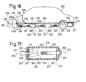
- the motor vehicle 201 shown in FIG. 18 again consists of a passenger car, has a vehicle body 202 with a body 203, a vehicle floor 204 and a frame 205, an internal combustion engine 206 with an engine housing 206a and an exhaust system 211 with an exhaust 212 -
- an intake and collection device 213 with an exhaust manifold and a common outlet 213a a first elastically deformable line element 216, a rigid pipe 217 a second elastically deformable pipe element 218, a catalytic converter 219, a pipe 220, a third elastically deformable pipe element 221, a first silencer 222, a pipe 223, a fourth elastically deformable pipe element 224, a pipe 225, a second silencer 226 and an outlet pipe 227.
- the catalytic converter 219 is therefore arranged downstream of the elastically deformable line elements 216, 218 and is located below the vehicle floor 204.
- the catalytic converter 219 is elongated and has an axis approximately parallel to the longitudinal direction of the motor vehicle and a housing 235 with a jacket 237 and two end walls 238 , 239.
- the jacket 237 has, for example, the shape of a flattened oval or a circle in cross section.
- the end walls 238, 239 are, for example, at least partially conical and / or curved and inclined towards the axis.
- Housing 235 contains catalytic agents for catalytic purification of the exhaust gas.
- the jacket and the end walls of the housing of the catalytic converter 219 can have wall thicknesses similar to those given above for the silencer housing of the exhaust 12.
- the catalytic converter housing 235 can possibly contain sound-absorbing and heat-insulating fiber materials which are arranged analogously to the silencers of the exhaust pipe 12 described first.
- the exhaust system 211 also has holding means 241, which hold the housing of the catalytic converter and the two mufflers on the vehicle floor 204.
- the holding means have two holders 243 for holding the catalytic converter housing 235 and two holders 244, 245 each for holding the housings of the silencers 222 and 226, respectively.
- the brackets 243, 244, 245 are of the same or similar design as the brackets described above and in particular each have two connecting members which consist entirely or partially of a rubber body. Unless otherwise stated, the exhaust system can 211 may be of the same or similar design as the exhaust system 11.
- Device 251 shown in FIG. 19 forms a combined catalytic converter silencer and has an elongated housing 255 with an axis 256, a jacket 257 and two end walls 258, 259.
- the housing 255 contains, for example, similar to the muffler housing of the exhaust 12, two gas-permeable partition walls 260, 261, a gas-permeable inner jacket 265 and heat-insulating and sound-absorbing fiber materials 267, 268, 269.
- the jacket 257, the end walls 258, 259, the partition walls 260, 261 and the inner jacket 265 can be configured similarly and have similar wall thicknesses as in the silencers of the exhaust pipe 12.
- the intermediate walls and the inner jacket delimit a hollow interior 270.
- the housing 255 is provided with an inlet 271 and an outlet 272 at its end walls and contains catalyst means 275. These divide the interior 270 into a first, inner interior region 277 and a second, outer interior region 278.
- the inlet 271 opens into the first interior area 277 at the intermediate wall 260.
- the outlet 272 is formed by a tube which projects into the second interior area 278 and is, for example, of a similar design to the tube 54 of the muffler 19 shown in FIG. 3.
- the catalyst means 275 are used for the catalytic purification of the exhaust gas and have a multiplicity of passages which connect the first to the second interior area.
- the catalyst means 275 can, for example, have two catalyst bodies arranged in a V-shape and can be of a similar design as is known from US Pat. No. 5,593,645 and the corresponding EP 0 676 535 A. The content of these publications is hereby included in this application as long as there are no contradictions.
- the housing 255 is held on the vehicle floor by two holders 291.
- the holders 291 can be designed similarly to the holders of the silencers described above.
- the device 251 which is used both for catalytic exhaust gas purification and for sound damping, can be installed, for example, in place of the first silencer 19 in the exhaust 12 shown in FIG. 1.
- the catalytic converter 14 of the exhaust 12 then only serves as a pre- and / or start catalytic converter and can be dimensioned relatively small.
- Device 251 may also replace catalytic converter 218 and first muffler 222 of exhaust 212 shown in FIG. 18.
- the motor vehicle and its exhaust system can still be changed in various ways.
- a pre- and / or start catalytic converter can be provided, which, like the catalytic converter 14 in FIG. 1, is rigidly connected to the intake and collection device 213 and upstream of the first elastically deformable line element is arranged.
- each exhaust can be connected to a few cylinders of the internal combustion engine of the vehicle and, moreover, can be designed in the manner described. If the engine consists of a diesel engine, the catalyst can be omitted. Furthermore, the exhaust may have only a single silencer.
- one of the two can be made elastic in the exhaust 12 or 212 shown in FIGS. 1 and 18 omit deformable line elements 16 and 18 or 216 and 218.
- the pipes and silencers can have larger diameters than in a passenger car.
- the wall thicknesses of the tubes, the catalytic converter and / or muffler housing arranged downstream of at least one elastically deformable line element and held on the vehicle body, and the intermediate walls and inner sheaths can nevertheless be, for example, only about 0.5 mm or a little more.
- the holders can then possibly be attached at least in part to the frame instead of to the vehicle floor of the motor vehicle.
- each housing can possibly connect to the vehicle body only with three at least partially rubber-elastic connecting members.
- the three connecting elements should then not all lie on the same straight line and should preferably form a triangle in a right-angled projection onto the plane on which the vehicle is standing.
- at least one or each silencer can be connected to the vehicle floor and / or frame using only a single holder.
- a catalyst and / or muffler housing arranged downstream of at least one elastically deformable line element and preferably downstream of two such can be attached more or less rigidly to the vehicle body even without rubber-elastic connecting elements at one connection point or several connection points.
- the silencers or at least one of them can have a housing, the jacket of which is, for example, approximately oval in cross section instead of circular.
Landscapes
- Engineering & Computer Science (AREA)
- Chemical & Material Sciences (AREA)
- Combustion & Propulsion (AREA)
- Mechanical Engineering (AREA)
- General Engineering & Computer Science (AREA)
- Chemical Kinetics & Catalysis (AREA)
- Health & Medical Sciences (AREA)
- Toxicology (AREA)
- Transportation (AREA)
- Exhaust Silencers (AREA)
- Cooling, Air Intake And Gas Exhaust, And Fuel Tank Arrangements In Propulsion Units (AREA)
- Exhaust Gas After Treatment (AREA)
Applications Claiming Priority (3)
| Application Number | Priority Date | Filing Date | Title |
|---|---|---|---|
| CH01223/96A CH691459A5 (de) | 1996-05-13 | 1996-05-13 | Abgasanlage für ein Kraftfahrzeug und Kraftfahrzeug. |
| CH1223/96 | 1996-05-13 | ||
| CH122396 | 1996-05-13 |
Publications (3)
| Publication Number | Publication Date |
|---|---|
| EP0807749A2 true EP0807749A2 (fr) | 1997-11-19 |
| EP0807749A3 EP0807749A3 (fr) | 1998-02-04 |
| EP0807749B1 EP0807749B1 (fr) | 2003-10-08 |
Family
ID=4205376
Family Applications (1)
| Application Number | Title | Priority Date | Filing Date |
|---|---|---|---|
| EP97810288A Expired - Lifetime EP0807749B1 (fr) | 1996-05-13 | 1997-05-07 | Dispositif d'échappement pour un véhicule automobile, ainsi que véhicule automobile |
Country Status (8)
| Country | Link |
|---|---|
| US (1) | US6058702A (fr) |
| EP (1) | EP0807749B1 (fr) |
| JP (1) | JPH1047033A (fr) |
| KR (1) | KR970075238A (fr) |
| BR (1) | BR9703139A (fr) |
| CH (1) | CH691459A5 (fr) |
| DE (1) | DE59710825D1 (fr) |
| ES (1) | ES2208852T3 (fr) |
Cited By (17)
| Publication number | Priority date | Publication date | Assignee | Title |
|---|---|---|---|---|
| EP0925984A1 (fr) | 1997-12-17 | 1999-06-30 | Scambia Industrial Developments Aktiengesellschaft | Système d'échappement pour véhicule automobile ainsi que véhicule automobile et procédé pour la formation d'un système d'échappement |
| EP0945297A1 (fr) * | 1998-03-23 | 1999-09-29 | Volkswagen Aktiengesellschaft | Système d'échappement pour un véhicule automobile |
| EP0950460A1 (fr) | 1998-04-17 | 1999-10-20 | Scambia Industrial Developments Aktiengesellschaft | Méthode de fabrication de l'enceinte d'un silencieux d'échappement, et enceinte fabriquée |
| EP1013905A1 (fr) * | 1998-12-18 | 2000-06-28 | Volkswagen Aktiengesellschaft | Agencement d'un catalyseur à un moteur à combustion interne |
| WO2000061926A1 (fr) * | 1999-04-14 | 2000-10-19 | Llanelli Radiators Limited | Systeme de tuyau d'echappement pour vehicule |
| US6173800B1 (en) | 1997-04-28 | 2001-01-16 | Scambia Industrial Developments Ag | Exhaust system for a motor vehicle and motor vehicle |
| EP1104839A1 (fr) | 1999-12-01 | 2001-06-06 | Scambia Industrial Developments Aktiengesellschaft | Dispositif d'échappement pour un véhicule, véhicule et procédé de fabrication de ce dispositif |
| EP1132675A1 (fr) * | 2000-03-08 | 2001-09-12 | Siemens Canada Limited | Assemblage étanche de tubes, à faible perte de charge avec un soufflet |
| EP1162098A1 (fr) * | 2000-06-08 | 2001-12-12 | Peugeot Citroen Automobiles SA | Véhicule automobile à moteur thermique comportant une ligne d'échappement ayant un système de dépollution placé à l'avant du moteur |
| EP1953023A3 (fr) * | 2007-02-05 | 2009-09-02 | Toyota Jidosha Kabushiki Kaisha | Montage d'un échangeur thermique de système d'échappement sur carrosserie de véhicule |
| DE102009006503A1 (de) | 2009-01-28 | 2010-08-19 | Benteler Automobiltechnik Gmbh | Abgasanlage für ein Kraftfahrzeug |
| DE10023781B4 (de) * | 2000-05-15 | 2012-02-23 | Anvis Deutschland Gmbh | Befestigungsvorrichtung für ein schwingfähiges Bauelement |
| FR2968711A1 (fr) * | 2010-12-14 | 2012-06-15 | Peugeot Citroen Automobiles Sa | Ligne d'echappement pour vehicule automobile et methode d'epuration de gaz d'echappement produits par un moteur thermique equipant ce vehicule |
| DE102014001090B3 (de) * | 2014-01-29 | 2015-06-25 | Audi Ag | Abgasanlage in einem Kraftfahrzeug |
| EP2985167A1 (fr) * | 2014-08-14 | 2016-02-17 | CNH Industrial Italia S.p.A. | Ensemble de montage de silencieux horizontal pour véhicule tout-terrain |
| WO2017216105A1 (fr) * | 2016-06-15 | 2017-12-21 | Jaguar Land Rover Limited | Système d'échappement de véhicule |
| DE102017219721A1 (de) | 2017-11-07 | 2019-05-09 | Bayerische Motoren Werke Aktiengesellschaft | Abgastrakt für eine Verbrennungskraftmaschine eines Kraftfahrzeugs sowie Kraftfahrzeug |
Families Citing this family (36)
| Publication number | Priority date | Publication date | Assignee | Title |
|---|---|---|---|---|
| JP2001123829A (ja) * | 1999-10-25 | 2001-05-08 | Honda Motor Co Ltd | カバー部材取付構造 |
| CN2499728Y (zh) * | 2001-08-10 | 2002-07-10 | 金达塑胶五金制品(深圳)有限公司 | 微波炉用耳把式金属食物加热盘 |
| CN2490934Y (zh) * | 2001-08-10 | 2002-05-15 | 金达塑胶五金制品(深圳)有限公司 | 微波炉用金属食物加热盘 |
| JP4691289B2 (ja) * | 2001-09-27 | 2011-06-01 | 東京濾器株式会社 | 触媒マフラ |
| US6415603B1 (en) * | 2001-10-04 | 2002-07-09 | Ford Global Technologies, Inc. | Flexible connector assembly |
| RU2227831C1 (ru) * | 2002-10-01 | 2004-04-27 | Ооо "Энерготехконтракт" | Нейтрализатор-глушитель |
| JP2004132320A (ja) * | 2002-10-11 | 2004-04-30 | Toyota Motor Corp | 排気管構造 |
| DE10353594B4 (de) * | 2003-11-17 | 2013-08-01 | Friedrich Boysen Gmbh & Co. Kg | Schalldämpfer |
| US20050155816A1 (en) * | 2004-01-16 | 2005-07-21 | Alcini William V. | Dynamic exhaust system for advanced internal combustion engines |
| DE202004000659U1 (de) * | 2004-01-17 | 2004-04-15 | Heinrich Gillet Gmbh | Schalldämpfer für Kraftfahrzeuge mit Verbrennungsmotor |
| US7721537B2 (en) * | 2004-01-27 | 2010-05-25 | Cummins Power Generation Inc. | Exhaust assembly |
| FR2870169B1 (fr) * | 2004-05-17 | 2006-06-23 | Renault Sas | Dispositif de maintien d'un ecran thermique |
| JP2006009753A (ja) * | 2004-06-29 | 2006-01-12 | Nissan Motor Co Ltd | 車両用エンジン排気装置 |
| DE102006029087A1 (de) * | 2006-06-24 | 2008-01-03 | Elringklinger Ag | Strukturbauteil, insbesondere Abschirmteil in Form eines Hitzeschildes |
| DE202007009806U1 (de) * | 2007-06-01 | 2008-07-03 | Bdd Beteiligungs Gmbh | Isoliervorrichtung für ein Maschinenelement, insbesondere Abgasrohr |
| FR2917122B1 (fr) * | 2007-06-08 | 2009-09-04 | Faurecia Sys Echappement | Silencieux pour ligne d'echappement de vehicule automobile |
| JP5001085B2 (ja) * | 2007-08-01 | 2012-08-15 | 日立建機株式会社 | 建設機械 |
| US20100236226A1 (en) * | 2009-03-19 | 2010-09-23 | Goodman Ball, Inc. | Exhaust system and method for an internal combustion engine and a generator set utilizing same |
| ES2386074B1 (es) * | 2010-03-26 | 2013-06-20 | Atein Naval Atenasa Sistemas Ecologicos S.L. | Tubo de escape para automotores con sistema de aislamiento termico y acustico. |
| DE102010047275A1 (de) * | 2010-10-01 | 2012-04-05 | Emitec Gesellschaft Für Emissionstechnologie Mbh | Abgasanlage |
| DE102010062335A1 (de) * | 2010-12-02 | 2012-06-06 | J. Eberspächer GmbH & Co. KG | Fahrzeugbauteil |
| FR2972022B1 (fr) * | 2011-02-25 | 2013-03-15 | Peugeot Citroen Automobiles Sa | Vehicule automobile comportant une ligne d'echappement dont les moyens acoustiques sont disposes en avant du train arriere |
| JP5637064B2 (ja) * | 2011-05-13 | 2014-12-10 | トヨタ自動車株式会社 | 可変圧縮比内燃機関の排気装置 |
| DE102011102099A1 (de) * | 2011-05-20 | 2012-11-22 | GM Global Technology Operations LLC (n. d. Gesetzen des Staates Delaware) | Auspufflagereinrichtung und Kraftfahrzeug |
| DE102011112633B4 (de) * | 2011-09-05 | 2015-06-11 | Faurecia Emissions Control Technologies, Germany Gmbh | Abgasrohrbaugruppe sowie Verfahren zur Befestigung eines Befestigungsblechs an einem Abgasrohr |
| CN102852594A (zh) * | 2012-09-12 | 2013-01-02 | 昆山西马克动力机械有限公司 | 消声器 |
| US8672090B1 (en) | 2012-09-30 | 2014-03-18 | Favrecia Emissions Control Technologies | Exhaust component with vibration isolated pipe |
| US9470134B2 (en) * | 2014-04-17 | 2016-10-18 | Honda Motor Co., Ltd | Muffler mount structure |
| US10240508B2 (en) * | 2014-12-09 | 2019-03-26 | American Boa, Inc. | Decoupler for flexible connection of exhaust pipes |
| GB2539248A (en) * | 2015-06-12 | 2016-12-14 | Jaguar Land Rover Ltd | Vehicle exhaust assembly |
| FR3065488B1 (fr) * | 2017-04-20 | 2019-06-28 | Faurecia Systemes D'echappement | Element de ligne d'echappement et procede de fabrication d'un tel element |
| US11959406B2 (en) * | 2020-12-30 | 2024-04-16 | Ferrari S.P.A. | Car provided with an exhaust system with aerodynamic effect |
| CN112984266B (zh) * | 2021-04-02 | 2023-03-14 | 河北亚大汽车塑料制品有限公司 | 一种用于碳罐电磁阀前的消音元件 |
| DE102022131738A1 (de) * | 2022-11-30 | 2024-06-06 | Hug Engineering Ag | Schalldämpfer für eine Abgasanlage |
| US12480432B2 (en) * | 2023-09-08 | 2025-11-25 | Thermo King Llc | Remote diesel oxidation catalyst for a prime mover of a transport power system |
| DE102023004324B3 (de) | 2023-10-27 | 2025-02-20 | Mercedes-Benz Group AG | Leitungseinrichtung für ein Kraftfahrzeug sowie Verbrennungskraftmaschine für ein Kraftfahrzeug |
Family Cites Families (23)
| Publication number | Priority date | Publication date | Assignee | Title |
|---|---|---|---|---|
| US2081546A (en) * | 1934-03-29 | 1937-05-25 | Hupp Motor Car Corp | Muffler mounting |
| US3490794A (en) * | 1968-06-28 | 1970-01-20 | Caterpillar Tractor Co | Exhaust manifold joints |
| US4060143A (en) * | 1975-02-05 | 1977-11-29 | Kabushiki Kaisha Komatsu Seisakusho | Muffler mounting apparatus in construction machinery |
| DE2620521A1 (de) * | 1976-05-10 | 1977-12-01 | Volkswagenwerk Ag | Schwingungsisolierende aufhaengung fuer eine heisse leitung, insbesondere eine auspuffleitung |
| CH615247A5 (fr) * | 1976-12-30 | 1980-01-15 | Sulzer Ag | |
| JPS594818Y2 (ja) * | 1979-07-16 | 1984-02-13 | 本田技研工業株式会社 | 発熱部の車体への支持装置 |
| JPS5853608B2 (ja) * | 1979-11-14 | 1983-11-30 | 富士重工業株式会社 | 車両用マフラの取付方法 |
| DE3026730C2 (de) * | 1980-07-15 | 1982-09-02 | Adam Opel AG, 6090 Rüsselsheim | Auspuffanlage mit Schalldämpfer und Aufhängung |
| DE3137746A1 (de) * | 1981-09-23 | 1983-06-09 | Volkswagenwerk Ag, 3180 Wolfsburg | "abgasanlage fuer die brennkraftmaschine eines fahrzeugs" |
| JPS5963314A (ja) * | 1982-09-07 | 1984-04-11 | Asahi Kiki Kk | 消音装置 |
| NL8502040A (nl) * | 1985-07-16 | 1987-02-16 | Volvo Car Bv | Werkwijze en gereedschap voor het tot stand brengen van een gasdichte buisverbinding en aldus vervaardigde verbinding. |
| US4867269A (en) * | 1987-06-30 | 1989-09-19 | Titeflex Corporation | Tuned self-damping convoluted conduit |
| JPS6412020A (en) * | 1987-07-06 | 1989-01-17 | Mazda Motor | Exhaust system structure for engine |
| DE3724087A1 (de) * | 1987-07-21 | 1989-02-02 | Leistritz Ag | Abgasschalldaempfer |
| DE8716385U1 (de) * | 1987-12-11 | 1988-02-25 | Wiegand, Frank, 6466 Gründau | Auspuffanlage eines Dieselmotors, insbesondere zur Anwendung bei Kraftfahrzeugen |
| US5195607A (en) * | 1989-11-21 | 1993-03-23 | Mazda Motor Corporation | Exhaust system for automotive engine |
| DE4036002A1 (de) * | 1990-11-12 | 1992-05-14 | Draebing Kg Wegu | Aufhaengeoese fuer eine abgasanlage eines kraftfahrzeugs |
| JP2521192B2 (ja) * | 1991-01-28 | 1996-07-31 | 東海ゴム工業株式会社 | 車両用排気管の支持方法とそれを実施するための構造 |
| US5297517A (en) * | 1991-08-19 | 1994-03-29 | Caterpillar Inc. | Noise suppression enclosure for an engine |
| JP2568751Y2 (ja) * | 1992-02-28 | 1998-04-15 | 三恵技研工業株式会社 | 排気浄化装置 |
| US5331810A (en) * | 1992-05-21 | 1994-07-26 | Arvin Industries, Inc. | Low thermal capacitance exhaust system for an internal combustion engine |
| JP3451706B2 (ja) * | 1993-07-09 | 2003-09-29 | マツダ株式会社 | エンジンの排気装置 |
| JPH0828257A (ja) * | 1994-07-11 | 1996-01-30 | Toyota Motor Corp | 二重排気管 |
-
1996
- 1996-05-13 CH CH01223/96A patent/CH691459A5/de not_active IP Right Cessation
-
1997
- 1997-05-07 EP EP97810288A patent/EP0807749B1/fr not_active Expired - Lifetime
- 1997-05-07 ES ES97810288T patent/ES2208852T3/es not_active Expired - Lifetime
- 1997-05-07 DE DE59710825T patent/DE59710825D1/de not_active Expired - Lifetime
- 1997-05-08 US US08/853,183 patent/US6058702A/en not_active Expired - Lifetime
- 1997-05-12 KR KR1019970018197A patent/KR970075238A/ko not_active Abandoned
- 1997-05-12 JP JP9121247A patent/JPH1047033A/ja active Pending
- 1997-05-13 BR BR9703139A patent/BR9703139A/pt not_active IP Right Cessation
Cited By (23)
| Publication number | Priority date | Publication date | Assignee | Title |
|---|---|---|---|---|
| US6173800B1 (en) | 1997-04-28 | 2001-01-16 | Scambia Industrial Developments Ag | Exhaust system for a motor vehicle and motor vehicle |
| EP0925984A1 (fr) | 1997-12-17 | 1999-06-30 | Scambia Industrial Developments Aktiengesellschaft | Système d'échappement pour véhicule automobile ainsi que véhicule automobile et procédé pour la formation d'un système d'échappement |
| EP0945297A1 (fr) * | 1998-03-23 | 1999-09-29 | Volkswagen Aktiengesellschaft | Système d'échappement pour un véhicule automobile |
| EP0950460A1 (fr) | 1998-04-17 | 1999-10-20 | Scambia Industrial Developments Aktiengesellschaft | Méthode de fabrication de l'enceinte d'un silencieux d'échappement, et enceinte fabriquée |
| EP1013905A1 (fr) * | 1998-12-18 | 2000-06-28 | Volkswagen Aktiengesellschaft | Agencement d'un catalyseur à un moteur à combustion interne |
| WO2000061926A1 (fr) * | 1999-04-14 | 2000-10-19 | Llanelli Radiators Limited | Systeme de tuyau d'echappement pour vehicule |
| EP1104839A1 (fr) | 1999-12-01 | 2001-06-06 | Scambia Industrial Developments Aktiengesellschaft | Dispositif d'échappement pour un véhicule, véhicule et procédé de fabrication de ce dispositif |
| US6390138B2 (en) | 2000-03-08 | 2002-05-21 | Siemens Canada Limited | Low restriction hose and seal assembly |
| EP1132675A1 (fr) * | 2000-03-08 | 2001-09-12 | Siemens Canada Limited | Assemblage étanche de tubes, à faible perte de charge avec un soufflet |
| DE10023781C5 (de) * | 2000-05-15 | 2014-12-31 | Anvis Deutschland Gmbh | Befestigungsvorrichtung für ein schwingfähiges Bauelement |
| DE10023781B4 (de) * | 2000-05-15 | 2012-02-23 | Anvis Deutschland Gmbh | Befestigungsvorrichtung für ein schwingfähiges Bauelement |
| FR2810075A1 (fr) * | 2000-06-08 | 2001-12-14 | Peugeot Citroen Automobiles Sa | Vehicule automobile a moteur thermique comportant une ligne d'echappement ayant un systeme de depollution place a l'avant du moteur |
| EP1162098A1 (fr) * | 2000-06-08 | 2001-12-12 | Peugeot Citroen Automobiles SA | Véhicule automobile à moteur thermique comportant une ligne d'échappement ayant un système de dépollution placé à l'avant du moteur |
| EP1953023A3 (fr) * | 2007-02-05 | 2009-09-02 | Toyota Jidosha Kabushiki Kaisha | Montage d'un échangeur thermique de système d'échappement sur carrosserie de véhicule |
| US8074762B2 (en) | 2007-02-05 | 2011-12-13 | Toyota Jidosha Kabushiki Kaisha | Vehicle body mounting configuration including exhaust system heat exchanger |
| DE102009006503A1 (de) | 2009-01-28 | 2010-08-19 | Benteler Automobiltechnik Gmbh | Abgasanlage für ein Kraftfahrzeug |
| EP2466084A1 (fr) * | 2010-12-14 | 2012-06-20 | Peugeot Citroën Automobiles SA | Ligne d'échappement pour véhicule automobile et méthode d'épuration de gaz d'échappement produits par un moteur thermique équipant ce véhicule |
| FR2968711A1 (fr) * | 2010-12-14 | 2012-06-15 | Peugeot Citroen Automobiles Sa | Ligne d'echappement pour vehicule automobile et methode d'epuration de gaz d'echappement produits par un moteur thermique equipant ce vehicule |
| DE102014001090B3 (de) * | 2014-01-29 | 2015-06-25 | Audi Ag | Abgasanlage in einem Kraftfahrzeug |
| EP2985167A1 (fr) * | 2014-08-14 | 2016-02-17 | CNH Industrial Italia S.p.A. | Ensemble de montage de silencieux horizontal pour véhicule tout-terrain |
| US9869229B2 (en) | 2014-08-14 | 2018-01-16 | Cnh Industrial America Llc | Horizontal muffler mounting assembly for an off-road vehicle |
| WO2017216105A1 (fr) * | 2016-06-15 | 2017-12-21 | Jaguar Land Rover Limited | Système d'échappement de véhicule |
| DE102017219721A1 (de) | 2017-11-07 | 2019-05-09 | Bayerische Motoren Werke Aktiengesellschaft | Abgastrakt für eine Verbrennungskraftmaschine eines Kraftfahrzeugs sowie Kraftfahrzeug |
Also Published As
| Publication number | Publication date |
|---|---|
| US6058702A (en) | 2000-05-09 |
| JPH1047033A (ja) | 1998-02-17 |
| EP0807749B1 (fr) | 2003-10-08 |
| CH691459A5 (de) | 2001-07-31 |
| ES2208852T3 (es) | 2004-06-16 |
| DE59710825D1 (de) | 2003-11-13 |
| BR9703139A (pt) | 1998-09-08 |
| EP0807749A3 (fr) | 1998-02-04 |
| KR970075238A (ko) | 1997-12-10 |
Similar Documents
| Publication | Publication Date | Title |
|---|---|---|
| EP0807749B1 (fr) | Dispositif d'échappement pour un véhicule automobile, ainsi que véhicule automobile | |
| EP0875410B1 (fr) | Dispositif d'échappement pour véhicules automobiles, ainsi que pour un véhicule automobile | |
| EP1104839B1 (fr) | Dispositif d'échappement pour un véhicule, véhicule et procédé de fabrication de ce dispositif | |
| EP0875409B1 (fr) | Système d'échappement pour véhicules automobiles et procédé pour la formation d'un système d'échappement | |
| DE4303950C1 (de) | In einem inneren und einem äußeren Mantelrohr gehalterter metallischer Wabenkörper, insbesondere Katalysator-Trägerkörper | |
| DE10307506A1 (de) | Abgasanlage | |
| DE2907320C2 (de) | Schalldämpfer für die Auspuffleitung einer Brennkraftmaschine | |
| EP1213538A2 (fr) | Dispositif pour gaz d'échappement comprenant un résonateur de Helmholtz | |
| DE19504223A1 (de) | Schalldämpfer für den Ansaugkanal einer Brennkraftmaschine | |
| DE1292667B (de) | Schalldaempfer fuer stroemende Gase | |
| DE3326260C2 (fr) | ||
| DE102010052938A1 (de) | Abgaseinrichtung für Quermotor | |
| DE4007724A1 (de) | Russfilter fuer dieselmotoren | |
| DE112011102983B4 (de) | Kompakter Coulomb-Dämpfer | |
| DE19706883C2 (de) | Abgas-Schalldämpfer für Kraftfahrzeuge mit Verbrennungsmotoren | |
| DE10008458B4 (de) | Abgassystem für ein Motorrad | |
| DE202020100885U1 (de) | Aufbau einer Schalldämpfereinheit | |
| DE10038796A1 (de) | Modul für Abgasanlagen von Verbrennungsmotoren | |
| EP0925984B1 (fr) | Système d'échappement pour véhicule automobile ainsi que véhicule automobile avec système d'échappement | |
| DE6608356U (de) | Abgasanlage mit schalldaempfer. | |
| DE3505401A1 (de) | Schalldaempfendes rohr zum uebertragen gasfoermiger medien | |
| DE2505135A1 (de) | Vorrichtung zur verringerung akustischer energie | |
| EP1619364B1 (fr) | Antivibrateur | |
| DE602004002857T2 (de) | Schalldämpfervorrichtung | |
| WO1998019054A1 (fr) | Silencieux |
Legal Events
| Date | Code | Title | Description |
|---|---|---|---|
| PUAI | Public reference made under article 153(3) epc to a published international application that has entered the european phase |
Free format text: ORIGINAL CODE: 0009012 |
|
| AK | Designated contracting states |
Kind code of ref document: A2 Designated state(s): BE DE ES FR GB IT NL SE |
|
| PUAL | Search report despatched |
Free format text: ORIGINAL CODE: 0009013 |
|
| AK | Designated contracting states |
Kind code of ref document: A3 Designated state(s): BE DE ES FR GB IT NL SE |
|
| 17P | Request for examination filed |
Effective date: 19980327 |
|
| 17Q | First examination report despatched |
Effective date: 20010129 |
|
| GRAH | Despatch of communication of intention to grant a patent |
Free format text: ORIGINAL CODE: EPIDOS IGRA |
|
| GRAS | Grant fee paid |
Free format text: ORIGINAL CODE: EPIDOSNIGR3 |
|
| GRAA | (expected) grant |
Free format text: ORIGINAL CODE: 0009210 |
|
| RTI1 | Title (correction) |
Free format text: EXHAUST SYSTEM FOR A MOTOR VEHICLE AS WELL AS MOTOR VEHICLE |
|
| AK | Designated contracting states |
Kind code of ref document: B1 Designated state(s): BE DE ES FR GB IT NL SE |
|
| PG25 | Lapsed in a contracting state [announced via postgrant information from national office to epo] |
Ref country code: NL Free format text: LAPSE BECAUSE OF FAILURE TO SUBMIT A TRANSLATION OF THE DESCRIPTION OR TO PAY THE FEE WITHIN THE PRESCRIBED TIME-LIMIT Effective date: 20031008 |
|
| REG | Reference to a national code |
Ref country code: GB Ref legal event code: FG4D Free format text: NOT ENGLISH |
|
| GBT | Gb: translation of ep patent filed (gb section 77(6)(a)/1977) |
Effective date: 20031008 |
|
| REF | Corresponds to: |
Ref document number: 59710825 Country of ref document: DE Date of ref document: 20031113 Kind code of ref document: P |
|
| PG25 | Lapsed in a contracting state [announced via postgrant information from national office to epo] |
Ref country code: SE Free format text: LAPSE BECAUSE OF FAILURE TO SUBMIT A TRANSLATION OF THE DESCRIPTION OR TO PAY THE FEE WITHIN THE PRESCRIBED TIME-LIMIT Effective date: 20040108 |
|
| NLV1 | Nl: lapsed or annulled due to failure to fulfill the requirements of art. 29p and 29m of the patents act | ||
| REG | Reference to a national code |
Ref country code: ES Ref legal event code: FG2A Ref document number: 2208852 Country of ref document: ES Kind code of ref document: T3 |
|
| ET | Fr: translation filed | ||
| PLBE | No opposition filed within time limit |
Free format text: ORIGINAL CODE: 0009261 |
|
| STAA | Information on the status of an ep patent application or granted ep patent |
Free format text: STATUS: NO OPPOSITION FILED WITHIN TIME LIMIT |
|
| 26N | No opposition filed |
Effective date: 20040709 |
|
| PGFP | Annual fee paid to national office [announced via postgrant information from national office to epo] |
Ref country code: IT Payment date: 20060531 Year of fee payment: 10 |
|
| PGFP | Annual fee paid to national office [announced via postgrant information from national office to epo] |
Ref country code: ES Payment date: 20080619 Year of fee payment: 12 |
|
| PG25 | Lapsed in a contracting state [announced via postgrant information from national office to epo] |
Ref country code: IT Free format text: LAPSE BECAUSE OF NON-PAYMENT OF DUE FEES Effective date: 20070507 |
|
| PGFP | Annual fee paid to national office [announced via postgrant information from national office to epo] |
Ref country code: GB Payment date: 20090506 Year of fee payment: 13 |
|
| REG | Reference to a national code |
Ref country code: ES Ref legal event code: FD2A Effective date: 20090508 |
|
| PG25 | Lapsed in a contracting state [announced via postgrant information from national office to epo] |
Ref country code: ES Free format text: LAPSE BECAUSE OF NON-PAYMENT OF DUE FEES Effective date: 20090508 |
|
| GBPC | Gb: european patent ceased through non-payment of renewal fee |
Effective date: 20100507 |
|
| PG25 | Lapsed in a contracting state [announced via postgrant information from national office to epo] |
Ref country code: GB Free format text: LAPSE BECAUSE OF NON-PAYMENT OF DUE FEES Effective date: 20100507 |
|
| PGFP | Annual fee paid to national office [announced via postgrant information from national office to epo] |
Ref country code: BE Payment date: 20110511 Year of fee payment: 15 |
|
| BERE | Be: lapsed |
Owner name: *SCAMBIA INDUSTRIAL DEVELOPMENTS A.G. Effective date: 20120531 |
|
| PG25 | Lapsed in a contracting state [announced via postgrant information from national office to epo] |
Ref country code: BE Free format text: LAPSE BECAUSE OF NON-PAYMENT OF DUE FEES Effective date: 20120531 |
|
| REG | Reference to a national code |
Ref country code: FR Ref legal event code: PLFP Year of fee payment: 19 |
|
| PGFP | Annual fee paid to national office [announced via postgrant information from national office to epo] |
Ref country code: DE Payment date: 20150521 Year of fee payment: 19 |
|
| PGFP | Annual fee paid to national office [announced via postgrant information from national office to epo] |
Ref country code: FR Payment date: 20150521 Year of fee payment: 19 |
|
| REG | Reference to a national code |
Ref country code: DE Ref legal event code: R082 Ref document number: 59710825 Country of ref document: DE Representative=s name: HABBEL & HABBEL, DE Ref country code: DE Ref legal event code: R081 Ref document number: 59710825 Country of ref document: DE Owner name: SCAMBIA HOLDINGS CYPRUS LTD., CY Free format text: FORMER OWNER: SCAMBIA INDUSTRIAL DEVELOPMENTS AKTIENGESELLSCHAFT, SCHAAN, LI |
|
| REG | Reference to a national code |
Ref country code: FR Ref legal event code: TP Owner name: BOSAL EMISSION CONTROL SYSTEMS NV, BE Effective date: 20150908 |
|
| REG | Reference to a national code |
Ref country code: DE Ref legal event code: R119 Ref document number: 59710825 Country of ref document: DE |
|
| REG | Reference to a national code |
Ref country code: FR Ref legal event code: ST Effective date: 20170131 |
|
| PG25 | Lapsed in a contracting state [announced via postgrant information from national office to epo] |
Ref country code: DE Free format text: LAPSE BECAUSE OF NON-PAYMENT OF DUE FEES Effective date: 20161201 Ref country code: FR Free format text: LAPSE BECAUSE OF NON-PAYMENT OF DUE FEES Effective date: 20160531 |