EP0807728A2 - Coffrage pour la réalisation de colonnes en béton - Google Patents
Coffrage pour la réalisation de colonnes en béton Download PDFInfo
- Publication number
- EP0807728A2 EP0807728A2 EP97106129A EP97106129A EP0807728A2 EP 0807728 A2 EP0807728 A2 EP 0807728A2 EP 97106129 A EP97106129 A EP 97106129A EP 97106129 A EP97106129 A EP 97106129A EP 0807728 A2 EP0807728 A2 EP 0807728A2
- Authority
- EP
- European Patent Office
- Prior art keywords
- formwork
- lugs
- units
- round
- longitudinal direction
- Prior art date
- Legal status (The legal status is an assumption and is not a legal conclusion. Google has not performed a legal analysis and makes no representation as to the accuracy of the status listed.)
- Withdrawn
Links
Images

Classifications
-
- E—FIXED CONSTRUCTIONS
- E04—BUILDING
- E04G—SCAFFOLDING; FORMS; SHUTTERING; BUILDING IMPLEMENTS OR AIDS, OR THEIR USE; HANDLING BUILDING MATERIALS ON THE SITE; REPAIRING, BREAKING-UP OR OTHER WORK ON EXISTING BUILDINGS
- E04G13/00—Falsework, forms, or shutterings for particular parts of buildings, e.g. stairs, steps, cornices, balconies foundations, sills
- E04G13/02—Falsework, forms, or shutterings for particular parts of buildings, e.g. stairs, steps, cornices, balconies foundations, sills for columns or like pillars; Special tying or clamping means therefor
- E04G13/021—Falsework, forms, or shutterings for particular parts of buildings, e.g. stairs, steps, cornices, balconies foundations, sills for columns or like pillars; Special tying or clamping means therefor for circular columns
Definitions
- the invention relates to a formwork for the production of round concrete columns, wherein one or more formwork units are pressed together to form a rigid hollow body and sealed.
- round concrete columns were mostly carried out using wooden formwork consisting of individual slats, which were attached to wreaths and assembled in a complex process and secured against the high pressures.
- Another common process using round formwork parts made of sheet steel elements is for small quantities or uneconomical for special connecting structures.
- the use of one-way formwork for round concrete columns is particularly widespread, for example a sheet metal tube which is folded together from a spirally wound sheet metal strip. After removing the metal strip, an impression remains in the concrete, which can only be removed in a post-treatment by plastering or filling.
- Another common method is the so-called cardboard formwork, the use of which for large quantities is uneconomical and is therefore not responsible, especially from an ecological point of view.
- connection arrangement is described, two adjacent formwork elements, in particular a circular formwork, being connected to one another in such a way that both parts are butted against one another without overlap and without folds, and are held together by the connection elements will.
- the formwork elements With the large pressure development that occurs at the joints of the formwork during concreting, the formwork elements are deformed between the connecting elements, so that joints are created through which the concrete can escape.
- the two formwork elements are not continuously secured against displacement due to the lack of toothing, so that they behave unstably, with the result that the two formwork elements yield in an uneven manner.
- Another disadvantage is. that the connection arrangement can be moved continuously like a hinge to one side and is therefore unstable. As a result, in addition to the joints already mentioned, bumps on the joint also occur.
- the formwork according to the invention has the task of eliminating the aforementioned deficiencies, the formwork units (1) being connected and sealed to one another in a simple manner to form a dimensionally stable hollow body. This object is achieved by the features listed in patent claims 1 and 2.
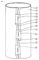
- the essential components are several wedge-shaped lugs (3) that belong together in pairs and are firmly connected to the abutting formwork units (1), which are mirror-symmetrically shaped and complement each other complementary to one another, but to the adjacent lugs (3) that belong together above and below. are horizontally offset.
- the two sides therefore connect to form a firmly connected unit with a predetermined shape based on the formwork diameter.
- the three mutually separate joints (7) consisting of the inner joint (7) of the formwork units (1), the circular surface (6) offset by 90 ° and the outer joint (7), in turn offset by 90 °, between the two approaches ( 3) result in a high degree of tightness in addition to the anchoring, since the connection from the inside to the outside is prevented by changing the direction three times. This is one of the most important criteria of the formwork according to the invention.
- the two wedge-shaped lugs (3) belonging together and arranged in pairs serve as guides (8) for the clamp (2) and are held together by them in pairs.
- the central offset (10) of the clip (2) is of crucial importance. This must be dimensioned and shaped so that the two inner surfaces (4) of the bracket (2) are tangential to the circular line (5) of the formwork unit (1).
- the two subsequent formwork units (1) also connect tangentially and stress-free to both lugs (3) and an exact circular line ( 5) form.
- the two pairs of approaches (3) are not only pressed together by the clip (2), but at the same time they are pressed onto the inner surfaces (4) of the cranked clip (2) and brought into the position assigned to the respective formwork diameter.
- a rod (9) welded onto the crank (10) is used for assembly in order to be able to strike the clamp (2) downwards or upwards.
- the angle (11) of the wedge-shaped bracket (2) is identical to the angle (11) of the wedge-shaped lugs (3), so that when the bracket (2) is moved longitudinally, the entire length of the two legs (13) always lies.
- the angle (11) of the two opposite lugs (3) is dimensioned such that the clamp (2) can be placed or removed in the de-energized state, but receives the guide (8) in the event of longitudinal displacement and is under tension. Since the vertical toothing (15) makes it impossible to move to either side, the paired approaches (3) are always exactly in position as a mirror image of one another. It is thus ensured that the joint (7) of the formwork units (1) is alternately but continuously covered over the entire height of the formwork by the shoulders (3), which causes the formwork to be watertight.
- the formwork according to the invention is assembled in such a way that when the formwork units (1) are joined together, the lugs (3) are necessarily in the correct position, the clamps (2) can be pushed onto the lugs (3), and by longitudinal displacement downwards Tension. When loosening the formwork, the clamps (2) are pushed back upwards and removed so that the formwork can be disassembled without tension.
- a sleeve (18) which is secured against vertical displacement by bases (19), these parts with lugs (3) and brackets (2) or with screws or with another Jig are held together, and can be equipped with tabs for fastening the formwork support.
- a sleeve (18) can be attached at any point on the formwork.
- sheet steel instead of sheet steel, another material, for example fiberglass, wood fiber cardboard, etc., can be used for the formwork units (1).
- Sheet steel can be riveted and glued or welded, whereas if another material is used for the formwork units (1), it is necessary for them to be edged and glued to the joints (7).
- U-rails are provided, on the legs of which the lugs (3) are welded.
- the formwork units (1) are pressed into the U-profile using adhesive. It is advisable to cover the inside of the formwork units (1), since on the one hand the material thickness of the U-rails (14) is compensated for, and on the other hand the concrete does not come into contact with the formwork units (1), especially if it does is an absorbent or rough material such as wood fiber cardboard.
- the formwork can also be used in the same way for the production of conical round columns, conical column bases or conical column heads (coves). Any other use as a silo, round container, round duct or sheet metal cladding is also possible.
Landscapes
- Engineering & Computer Science (AREA)
- Architecture (AREA)
- Mechanical Engineering (AREA)
- Civil Engineering (AREA)
- Structural Engineering (AREA)
- Forms Removed On Construction Sites Or Auxiliary Members Thereof (AREA)
Applications Claiming Priority (2)
| Application Number | Priority Date | Filing Date | Title |
|---|---|---|---|
| DE1996115062 DE19615062C2 (de) | 1996-04-17 | 1996-04-17 | Schalung zur Herstellung von Betonrundsäulen |
| DE19615062 | 1996-04-17 |
Publications (2)
| Publication Number | Publication Date |
|---|---|
| EP0807728A2 true EP0807728A2 (fr) | 1997-11-19 |
| EP0807728A3 EP0807728A3 (fr) | 1998-04-15 |
Family
ID=7791466
Family Applications (1)
| Application Number | Title | Priority Date | Filing Date |
|---|---|---|---|
| EP97106129A Withdrawn EP0807728A3 (fr) | 1996-04-17 | 1997-04-15 | Coffrage pour la réalisation de colonnes en béton |
Country Status (2)
| Country | Link |
|---|---|
| EP (1) | EP0807728A3 (fr) |
| DE (1) | DE19615062C2 (fr) |
Families Citing this family (3)
| Publication number | Priority date | Publication date | Assignee | Title |
|---|---|---|---|---|
| DE102006037677B4 (de) * | 2006-08-11 | 2010-02-25 | Oswald Knauer | Schalung und Verfahren zur Herstellung von Betonrundsäulen |
| WO2018136674A1 (fr) * | 2017-01-18 | 2018-07-26 | Create A Castle, LLC | Systèmes, dispositifs, et procédés servant à mouler des structures |
| US11408187B2 (en) * | 2017-01-18 | 2022-08-09 | Create A Castle, LLC | Mold systems having a separation tool for molding structures |
Family Cites Families (11)
| Publication number | Priority date | Publication date | Assignee | Title |
|---|---|---|---|---|
| US1405934A (en) * | 1919-09-05 | 1922-02-07 | Olson Fridolf | Column mold |
| US1641927A (en) * | 1926-08-19 | 1927-09-06 | Frank J Gremel | Mold fastener |
| US2273109A (en) * | 1939-02-27 | 1942-02-17 | M G Shutte | Form for concrete footing |
| FR1270366A (fr) * | 1960-10-14 | 1961-08-25 | Ouvrage préfabriqué et éléments pour sa construction | |
| FR2274202A7 (fr) * | 1974-05-14 | 1976-01-02 | Abate Robert | Dispositif de liaison pour elements de coffrage |
| DE3013496A1 (de) * | 1980-04-08 | 1981-10-15 | Peri-Werk Artur Schwörer KG, 7912 Weißenhorn | System-betonschaltung |
| AT393704B (de) * | 1982-06-29 | 1991-12-10 | Lehner Landwirtschaftsbau Ges | Verbindungsanordnung |
| FR2624174B1 (fr) * | 1987-12-07 | 1990-05-04 | Mills Echafaudages | Poutre metallique, en particulier en metal leger, notamment destinee a former des panneaux de coffrage |
| DE8902769U1 (de) * | 1989-03-07 | 1989-07-20 | Sundermann, Theodor, 4924 Barntrup | Spannschloß für aneinanderstoßende Platten o.dgl. |
| US5255888A (en) * | 1991-06-07 | 1993-10-26 | Deslauriers, Inc. | Concrete column form |
| DE4326310A1 (de) * | 1993-08-05 | 1995-02-09 | Oswald Knauer | Schalung zur Herstellung von Betonrundsäulen |
-
1996
- 1996-04-17 DE DE1996115062 patent/DE19615062C2/de not_active Expired - Fee Related
-
1997
- 1997-04-15 EP EP97106129A patent/EP0807728A3/fr not_active Withdrawn
Also Published As
| Publication number | Publication date |
|---|---|
| EP0807728A3 (fr) | 1998-04-15 |
| DE19615062C2 (de) | 1999-11-25 |
| DE19615062A1 (de) | 1997-10-23 |
Similar Documents
| Publication | Publication Date | Title |
|---|---|---|
| DE2826838B2 (de) | Verbindungselement, für Gerüste, Gestelle o.dgl. | |
| DE2343172A1 (de) | Baustahlgewebe | |
| EP0807728A2 (fr) | Coffrage pour la réalisation de colonnes en béton | |
| EP1272718B1 (fr) | Module de coffrage circulaire | |
| DE10160441B4 (de) | Säulenschalung | |
| DE3310895A1 (de) | Spannschiene zur befestigung duennwandiger haeute an einer tragenden unterkonstruktion | |
| DE2353231A1 (de) | Aus blech bestehendes langpaneel als bauelement fuer abgehaengte decken oder fassadenverkleidungen | |
| DE2528715B2 (de) | Vorgefertigtes Bauelement aus Stahlbeton zur Herstellung einer Winkelstützmauer od.dgl. | |
| EP0052761B1 (fr) | Dispositif pour serrer des éléments de coffrage | |
| DE2162202C3 (de) | Dichtleiste für Betonschalungen | |
| DE2118419C3 (de) | Treppengeländer | |
| DE9200503U1 (de) | Faltstore mit Kederprofilbefestigung | |
| EP0637661A2 (fr) | Coffrage pour colonnes rondes en béton | |
| DE3231220C2 (de) | Klammer zum Verbinden einander kreuzender Träger | |
| DE102006037677B4 (de) | Schalung und Verfahren zur Herstellung von Betonrundsäulen | |
| DE2814957C3 (de) | Silo, insbesondere zur Lagerung von Backmehl, sowie Verfahren zur Herstellung des Zylindermantels eines derartigen Silos | |
| DE2820725C3 (de) | Spannvorrichtung für im Abstand gegenüberstehende Schalungswände | |
| DE3248068C2 (de) | Behälter, insbesondere Rechteckbehälter mit Kunststoffwandungen | |
| DE8533999U1 (de) | Ausrichtwerkzeug zum Ausrichten derselben von Einzelsegmenten beim Bau von Großbehältern | |
| DE9316924U1 (de) | Rohrförmiger Verschalungs-Abstandhalter | |
| DE3874895T2 (de) | Verfahren zum befestigen einer traverse auf einer seitenstuetze, insbesondere in einem kabelgestell und verbindungsstelle auf diese weise geformt sowie ein profilstab fuer diese verbindung. | |
| DE202005009924U1 (de) | Schalung zum Herstellen eines im Querschnitt runden Betonbauteils | |
| DE2341050C3 (de) | Zweischalige, versetzbare Trennwand mit Fenster- und/oder Türeinbauten | |
| DE19924418A1 (de) | Bauelement zur Schubbewehrung | |
| DE2922915A1 (de) | Eckstuetze fuer zellensilos o.dgl. |
Legal Events
| Date | Code | Title | Description |
|---|---|---|---|
| PUAI | Public reference made under article 153(3) epc to a published international application that has entered the european phase |
Free format text: ORIGINAL CODE: 0009012 |
|
| AK | Designated contracting states |
Kind code of ref document: A2 Designated state(s): AT CH DE ES FR GB IT LI |
|
| PUAL | Search report despatched |
Free format text: ORIGINAL CODE: 0009013 |
|
| AK | Designated contracting states |
Kind code of ref document: A3 Designated state(s): AT CH DE ES FR GB IT LI |
|
| STAA | Information on the status of an ep patent application or granted ep patent |
Free format text: STATUS: THE APPLICATION IS DEEMED TO BE WITHDRAWN |
|
| 18D | Application deemed to be withdrawn |
Effective date: 19981016 |