EP0807569A2 - Dispositif de débrayage pour chaîne de bicyclette - Google Patents
Dispositif de débrayage pour chaîne de bicyclette Download PDFInfo
- Publication number
- EP0807569A2 EP0807569A2 EP97103188A EP97103188A EP0807569A2 EP 0807569 A2 EP0807569 A2 EP 0807569A2 EP 97103188 A EP97103188 A EP 97103188A EP 97103188 A EP97103188 A EP 97103188A EP 0807569 A2 EP0807569 A2 EP 0807569A2
- Authority
- EP
- European Patent Office
- Prior art keywords
- chain
- support
- swivel
- pivot
- profiles
- Prior art date
- Legal status (The legal status is an assumption and is not a legal conclusion. Google has not performed a legal analysis and makes no representation as to the accuracy of the status listed.)
- Granted
Links
Images

Classifications
-
- B—PERFORMING OPERATIONS; TRANSPORTING
- B62—LAND VEHICLES FOR TRAVELLING OTHERWISE THAN ON RAILS
- B62M—RIDER PROPULSION OF WHEELED VEHICLES OR SLEDGES; POWERED PROPULSION OF SLEDGES OR SINGLE-TRACK CYCLES; TRANSMISSIONS SPECIALLY ADAPTED FOR SUCH VEHICLES
- B62M9/00—Transmissions characterised by use of an endless chain, belt, or the like
- B62M9/16—Tensioning or adjusting equipment for chains, belts or the like
-
- F—MECHANICAL ENGINEERING; LIGHTING; HEATING; WEAPONS; BLASTING
- F16—ENGINEERING ELEMENTS AND UNITS; GENERAL MEASURES FOR PRODUCING AND MAINTAINING EFFECTIVE FUNCTIONING OF MACHINES OR INSTALLATIONS; THERMAL INSULATION IN GENERAL
- F16H—GEARING
- F16H7/00—Gearings for conveying rotary motion by endless flexible members
- F16H7/24—Equipment for mounting belts, ropes, or chains
Definitions
- the invention relates to a device for disengaging a bicycle chain and transferring it from a sprocket of the rear wheel to a guide connected to the bicycle frame for supporting the chain in the extended position for the purpose of disassembling the rear wheel.
- a sickle-shaped guide edge can be changed in the axial direction by means of a lever between two positions.
- the leading edge is pushed against the outer sprocket, after which the chain is placed over the sprocket against which the leading edge rests by appropriate actuation of the chain changer of the gear shift of the bicycle.
- the rear wheel can then be removed.
- the chain remains on the leading edge, being tensioned between the leading edge and the front sprocket by the chain changer.
- the bicycle chain can be placed on the leading edge from a rear sprocket without the chain having to be manipulated.
- the prerequisite is that the bicycle is equipped with a sprocket gear shift.
- the invention has for its object to improve a device of the type mentioned in such a way that it does not require additional axial space and that it can also be used in bicycles without sprocket gear shift, ie in bicycles with hub gear shift or in bicycles without gear shift is usable.
- the guide comprises a support element which can be pivoted in the chain plane and which can be pivoted from a starting position removed from the chain into a support position which engages the chain from the inside.
- a fixed nor an axially displaceable support element is therefore provided; instead, the support element is pivoted in the plane spanned by the upper and the lower chain center until it grips the chain from the inside and, as it were, lifts it off the sprocket.
- a support element which has at least one arched support edge in the direction of the chain, which in the support position rests on the webs of the chain links. The support edge is pivoted in the chain direction until it lifts the chain out of the toothing and, as it swings in, takes over its position to a certain extent.
- Support element for bicycles with hub gears or without gears, where there is very little free chain length, namely only according to the sag of the chain, that shows Support element according to another proposal according to the invention at least one support surface which is curved in the direction of the chain and which, in the support position, rests on the tension members of one side of the chain.
- the support element can also have two support surfaces for the opposing tension members of the chain, the support surfaces being expediently designed as webs directed against the ring gear of a U-shaped swivel profile enclosing the chain from three sides.
- the chain is lifted in a radial direction as a result of the pivoting movement of the support surface or both support surfaces, each of which engages in the chain from the side, a very small stroke being sufficient.
- the wheel Under the chain retained by the support surfaces, the wheel can emerge from the bearing slot after loosening the wheel nuts on both sides.
- the chain is supported in the same plane after the transfer and that the supporting edge or supporting surfaces of the supporting elements are pivoted in the radial direction within the chain plane, the plane spanned by the upper and lower chain center being the chain plane is understood.
- manually operable levers are provided, which are expediently pivoted after the rear wheel has been released, the chain being taken over by the support element during the increasing pivoting while the rear wheel exits the bearing slot. Without having to touch the chain with your hands, it is stretched between the support elements and the front sprocket after the rear wheel has been removed.
- the invention thus facilitates the transportation of the bicycle frame when the wheels are removed.
- the rear wheel can also be easily installed by pushing it into the bearing slots until the associated sprocket engages the chain again, at the same time pivoting the support elements out of engagement.
- the support element is articulated adjacent to the rear wheel axle on the frame part forming its bearing slot, in such a way that it can be pivoted about the articulation point from its front starting position into its rear support position.
- This embodiment is suitable is particularly suitable for a support element with an arched support edge.
- the support edge can have at least one tooth which projects radially outwards and engages in the chain links; by means of one or more such teeth, the support element can also be transported with the aid of the chain, in that the chain is driven by turning the pedals when the bicycle is unloaded.
- the drive direction depends on whether the support element is pivoted with its support edge around its respective articulation point from the inside of the chain against its upper or lower run.
- Another advantageous embodiment consists in that the support edge is formed on a segment sheet which is bent axially inwards on its circumference and has a radially outwardly bent edge in the form of the support edge on its inner edge.
- the segment sheet is advantageously articulated via a swivel bearing to a fastening tab attached to the inside of the frame part adjacent to the outermost sprocket.
- An axially outwardly projecting finger lever is provided on the segment plate for pivoting it. The user therefore only operates this finger lever; his hands touch when handing over the chain to the support element not the chain itself. The same applies to the reassembly of the rear wheel.
- the pivoting profile is arcuate and at one end can be pivoted about a frame-fixed pivot point located behind the chain in the middle of the chainring, such that the Support areas in the area of the other end of the swivel profile support the chain inwards.
- a particularly advantageous embodiment provides that two swivel profiles are arranged approximately symmetrically to the horizontal through the average height of the chain link, which can be actuated by a common swivel drive.
- the pivot drive expediently comprises a pivot cam which can be actuated by means of a pivot lever and which cooperates with projections on the mutually facing ends of the pivot profiles in such a way that the pivot profiles with their opposite ends are spread apart from the inside against the chain.
- Characterized in that the pivot cam is substantially elongated, it increases the distance between the projections accordingly with a rotation of 90 ° with the result that the outer ends of the Swivel cams can be spread from the inside against the chain.
- a position of the pivot points favoring the lever effect for pivoting the pivot profiles is achieved in that the frame part forming the bearing slot is extended to the rear by means of a frame plate receiving the pivot points for the pivot profiles.
- the swivel profiles are articulated so eccentrically at the swivel points of the frame plate that the mutually facing ends of the swivel profiles move towards the chain when they are spread. This movement allows the chain to yield inwards, with the previously released rear wheel emerging from the bearing slots simultaneously with the pivoting of the pivoting profiles.
- a suitable pivot lever for actuating the pivot cam is bent from below around the associated stub shaft, which forms the upper stop position corresponding to the starting position.
- the swivel lever can additionally have an upwardly directed mandrel just behind the axle stub for disengaging the axle stub from the bearing slot. So while pivoting the pivot lever the pivot profiles are increasingly spread apart, the mandrel ensures the disengaged rear wheel at the same time.
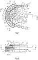
- FIG. 1 to 6 show a first embodiment of the device according to the invention.
- this embodiment is suitable for bicycles with hub gear shift or without gear shift, in which the sag of chain 1 is limited. This is the reason why the chain can only be lifted off the sprocket to a limited extent for the purpose of transferring it from a sprocket to a support element.
- This lifting is provided by the two pivot profiles 2, 3, which can be pivoted radially outward with their non-articulated ends by rotating a pivot cam 4 according to the arrows P1, P2.
- the two pivot profiles 2, 3 can each be pivoted with their ends oriented towards the center of the chain link about pivot points 5 of a frame plate 6, in which short eccentric levers 7 are connected, which are connected to the pivot profiles in a rotationally fixed manner.
- the ends of the swivel profiles 2, 3 oriented towards the center of the chain arch migrate inward when they are spread out, as shown in FIG. 3, so that after the chain is released by the gearwheel, more chain length is available for spreading the chain.
- the frame plate 6 has, as can be seen in Fig. 2, an angled mounting flange 8 which comprises the end of the frame part 10 containing the bearing slot 9 for the rear wheel and by means of a through screw 11 with the latter connected is.
- the two swivel profiles 2, 3 are held in their starting position by means of tension springs 12, which are anchored to the frame plate 6, so that they do not inadvertently come into engagement with the chain 1.
- the pivot cam 4 is seated on a pin 13 pivotably mounted in the frame part 10, at the other end of which a pivot lever 14 is fastened. With a corresponding bend, the pivot lever 14 engages under the side stub axle 15 of the rear wheel, the hub 16 of which is only indicated by an outline.
- the swivel lever 14 has on the rear side of the stub axle 15 an upwardly projecting mandrel 18 which, when the swivel lever 14 is actuated in the direction of arrow P3, moves against the stub axle 15 and consequently disengages it from the bearing slot 9.
- the pivot cam 4 is rotated from its horizontal position according to FIG. 1 into its vertical spread position according to FIG. 3, the rotational position of which is shown in FIG. 6 at a pivot angle of approximately 45 °.
- the rear wheel already released before the pivot lever 14 is actuated is first pushed with the aid of the mandrel 18 during pivoting of the pivot lever 14 then casually travels forward through the sloping bearing slot 9 until it comes out of engagement with the chain links.
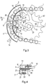
- the chain 1 is held on the inward-facing support surfaces 19 of the swivel profiles, as shown in FIGS. 3 and 6 and enlarged in FIG. 4.
- the two support profiles 2, 3 include the sprocket 17 in the area of the chain 1 in an approximately U-shaped manner, as is illustrated in FIG. There you can also see the pivot point 5 of the support profile 2 in the frame plate 6.
- the pivot cam 4 interacts with this, on both sides, inwardly projecting projections 20 of the support profiles 2, 3. Their flanks adjacent to the swivel cam 4 are always held in contact by means of the tension springs 12 and are correspondingly moved apart when the swivel cam 4 is swiveled until the maximum swivel position shown in FIG. 3 is reached.
- FIG. 6 shows a simplified illustration in that the frame plate 6 is omitted for clarity.
- FIG. 4 shows - after the gear 17 has been disengaged - a chain link abutting against the two support surfaces 19 with the lateral tension links 21, the tension links 21 of which are connected to one another via a web 22.
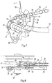
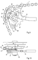
- FIG. 7 to 10 show a further embodiment of the invention, wherein the frame part 10 with the longitudinal slot 9 for receiving the wheel axle 23 of the rear wheel has at its lower end a bearing eye 33 for articulating a lever for tightening the chain in a chain gear shift. Since in this embodiment there is sufficient chain length for the transfer of the chain 1 to a support element designed as a segment plate 24, its simple swivel mounting around an articulation point 25 on the frame 10 is sufficient.
- the segment plate 24 has a support edge 26 on its circumference with a radially projecting tooth 27 at the top.
- the articulation point 25 of the segment plate 24 is mounted in a fastening tab 31 which comprises the frame part 10 in its rear area and which is fastened in the frame part 10 by means of two screws 32.
- the tooth 27 of the support edge 26 facilitates the pivoting of the segment plate 24 in the direction of the arrow P4 in that the chain 1 is moved to the left according to the arrow P5 after the tooth 27 engages in it.
- the segment plate 24 is automatically carried along by the tooth 27 until the tooth 27 has reached its end position shown in FIG. 9, in which it is supported with its rounded flank against a chain web 22.
- the segment sheet 24 is first bent along its circumference by 90 ° axially inwards, then again by 90 ° radially outwards, so that the support edge 26 thus formed is exactly in the plane of the outer ring gear 17 Chain connection between these and the chain engages, so that ultimately the support edge 26 engages approximately centrally on the inside of the chain stays 22.
Landscapes
- Engineering & Computer Science (AREA)
- Mechanical Engineering (AREA)
- General Engineering & Computer Science (AREA)
- Chemical & Material Sciences (AREA)
- Combustion & Propulsion (AREA)
- Transportation (AREA)
- Devices For Conveying Motion By Means Of Endless Flexible Members (AREA)
- Transmissions By Endless Flexible Members (AREA)
- Hand Tools For Fitting Together And Separating, Or Other Hand Tools (AREA)
- Steering Devices For Bicycles And Motorcycles (AREA)
Applications Claiming Priority (2)
| Application Number | Priority Date | Filing Date | Title |
|---|---|---|---|
| DE19620026A DE19620026C1 (de) | 1996-05-17 | 1996-05-17 | Vorrichtung zum Auskuppeln einer Fahrradkette |
| DE19620026 | 1996-05-17 |
Publications (3)
| Publication Number | Publication Date |
|---|---|
| EP0807569A2 true EP0807569A2 (fr) | 1997-11-19 |
| EP0807569A3 EP0807569A3 (fr) | 1998-12-09 |
| EP0807569B1 EP0807569B1 (fr) | 2003-08-20 |
Family
ID=7794639
Family Applications (1)
| Application Number | Title | Priority Date | Filing Date |
|---|---|---|---|
| EP97103188A Expired - Lifetime EP0807569B1 (fr) | 1996-05-17 | 1997-02-27 | Dispositif de débrayage pour chaíne de bicyclette |
Country Status (3)
| Country | Link |
|---|---|
| EP (1) | EP0807569B1 (fr) |
| AT (1) | ATE247577T1 (fr) |
| DE (2) | DE19620026C1 (fr) |
Cited By (1)
| Publication number | Priority date | Publication date | Assignee | Title |
|---|---|---|---|---|
| US20230079035A1 (en) * | 2021-09-15 | 2023-03-16 | TILT Industries LLC | Chain separator for manual bike training |
Families Citing this family (1)
| Publication number | Priority date | Publication date | Assignee | Title |
|---|---|---|---|---|
| DE102005006682B3 (de) * | 2005-02-15 | 2006-08-17 | Ulrich Rombach | Vorrichtung zum Abstützen der Antriebskette bei Fahrrädern |
Family Cites Families (7)
| Publication number | Priority date | Publication date | Assignee | Title |
|---|---|---|---|---|
| DE1118560B (de) * | 1958-05-16 | 1961-11-30 | Winkelhofer & Soehne Joh | Kettenraedergetriebe mit einer Kettenfuehrung |
| FR2172610A5 (fr) * | 1972-02-17 | 1973-09-28 | Micmo | |
| CH569204A5 (fr) * | 1972-09-15 | 1975-11-14 | Kropf Walter | |
| US3862487A (en) * | 1973-04-30 | 1975-01-28 | Gundy Kenneth Warren Van | Chain positioner for 10-speed bicycle |
| CH607823A5 (en) * | 1975-11-07 | 1978-11-15 | Tullio Campagnolo | Device enabling the bicycle transmission chain to be disengaged from the sprocket wheels of the free wheel |
| US4167125A (en) * | 1977-04-20 | 1979-09-11 | Eberhard Hedrich | Rear-wheel mounting for bicycle |
| FR2451855A1 (fr) * | 1979-03-20 | 1980-10-17 | Soulisse Jean | Repose chaine |
-
1996
- 1996-05-17 DE DE19620026A patent/DE19620026C1/de not_active Expired - Fee Related
-
1997
- 1997-02-27 DE DE59710598T patent/DE59710598D1/de not_active Expired - Fee Related
- 1997-02-27 EP EP97103188A patent/EP0807569B1/fr not_active Expired - Lifetime
- 1997-02-27 AT AT97103188T patent/ATE247577T1/de not_active IP Right Cessation
Cited By (3)
| Publication number | Priority date | Publication date | Assignee | Title |
|---|---|---|---|---|
| US20230079035A1 (en) * | 2021-09-15 | 2023-03-16 | TILT Industries LLC | Chain separator for manual bike training |
| GB2612188A (en) * | 2021-09-15 | 2023-04-26 | Tilt Ind Llc | Chain separator systems and methods |
| GB2612188B (en) * | 2021-09-15 | 2025-05-28 | Tilt Ind Llc | Chain separator systems and methods |
Also Published As
| Publication number | Publication date |
|---|---|
| DE59710598D1 (de) | 2003-09-25 |
| ATE247577T1 (de) | 2003-09-15 |
| DE19620026C1 (de) | 1997-07-24 |
| EP0807569A3 (fr) | 1998-12-09 |
| EP0807569B1 (fr) | 2003-08-20 |
Similar Documents
| Publication | Publication Date | Title |
|---|---|---|
| DE3308538C2 (fr) | ||
| DE2844122C2 (de) | Frontkettenschaltung für ein Fahrrad | |
| DE69731523T2 (de) | Zweirad-Radnaben-Montagevorrichtung | |
| DE69016320T2 (de) | Kettenradsatz für Fahrrad. | |
| DE20206816U1 (de) | Roller | |
| EP0341425A2 (fr) | Dispositif pour collationner des produits imprimés pliés | |
| DE3202382C2 (de) | Reversierbare Stauförderbahn | |
| EP0800977A2 (fr) | Dispositif de transport comprenant des moyens motorisés pour grimper des escaliers | |
| DE3123810C2 (de) | Förder- und Haltevorrichtung für einen gezähnten, bogenförmig geführten Anfahrstrang einer Stranggießmaschine | |
| DE19607837A1 (de) | Vorrichtung zum Dekorieren von einzelnen Objekten | |
| DE2933362C2 (fr) | ||
| DE10156992A1 (de) | Trittelementbefestigung für Personenbeförderer | |
| EP0807569B1 (fr) | Dispositif de débrayage pour chaíne de bicyclette | |
| EP0129089B1 (fr) | Appareil pour le transport des pots de ruban de fibres | |
| DE69610140T2 (de) | Aufhängevorrichtung für Fahrräder | |
| EP0512391B1 (fr) | Dispositif de déplacement de plaques-filtres dans un filtre-presse | |
| DE3130314C2 (fr) | ||
| DE1761754A1 (de) | Druckpresse | |
| DE3013854A1 (de) | Kettenschaltung mit automatischer seillaengenkompensation | |
| DE19642130A1 (de) | Einrichtung zur Übergabe von Druckprodukten | |
| DE920132C (de) | Vorrichtung zur passgerechten Bogenuebergabe mittels Greiferketten bei Druckmaschinen | |
| EP0970599B1 (fr) | Presse à balles rondes | |
| EP0732294B1 (fr) | Machine à faire des poches pliées | |
| DE4101882C2 (de) | Verstellbeschlag für Fahrzeugsitze, insbesondere Kraftfahrzeugsitze | |
| DE3507074A1 (de) | Endlosbahnanordnung |
Legal Events
| Date | Code | Title | Description |
|---|---|---|---|
| PUAI | Public reference made under article 153(3) epc to a published international application that has entered the european phase |
Free format text: ORIGINAL CODE: 0009012 |
|
| AK | Designated contracting states |
Kind code of ref document: A2 Designated state(s): AT BE CH DE DK ES FI FR GB IE IT LI MC NL SE |
|
| PUAL | Search report despatched |
Free format text: ORIGINAL CODE: 0009013 |
|
| AK | Designated contracting states |
Kind code of ref document: A3 Designated state(s): AT BE CH DE DK ES FI FR GB IE IT LI MC NL SE |
|
| 17P | Request for examination filed |
Effective date: 19990312 |
|
| 17Q | First examination report despatched |
Effective date: 20020906 |
|
| GRAH | Despatch of communication of intention to grant a patent |
Free format text: ORIGINAL CODE: EPIDOS IGRA |
|
| GRAS | Grant fee paid |
Free format text: ORIGINAL CODE: EPIDOSNIGR3 |
|
| GRAA | (expected) grant |
Free format text: ORIGINAL CODE: 0009210 |
|
| AK | Designated contracting states |
Designated state(s): AT BE CH DE DK ES FI FR GB IE IT LI MC NL SE |
|
| PG25 | Lapsed in a contracting state [announced via postgrant information from national office to epo] |
Ref country code: NL Free format text: LAPSE BECAUSE OF FAILURE TO SUBMIT A TRANSLATION OF THE DESCRIPTION OR TO PAY THE FEE WITHIN THE PRESCRIBED TIME-LIMIT Effective date: 20030820 Ref country code: IT Free format text: LAPSE BECAUSE OF FAILURE TO SUBMIT A TRANSLATION OF THE DESCRIPTION OR TO PAY THE FEE WITHIN THE PRESCRIBED TIME-LIMIT;WARNING: LAPSES OF ITALIAN PATENTS WITH EFFECTIVE DATE BEFORE 2007 MAY HAVE OCCURRED AT ANY TIME BEFORE 2007. THE CORRECT EFFECTIVE DATE MAY BE DIFFERENT FROM THE ONE RECORDED. Effective date: 20030820 Ref country code: IE Free format text: LAPSE BECAUSE OF FAILURE TO SUBMIT A TRANSLATION OF THE DESCRIPTION OR TO PAY THE FEE WITHIN THE PRESCRIBED TIME-LIMIT Effective date: 20030820 Ref country code: GB Free format text: LAPSE BECAUSE OF FAILURE TO SUBMIT A TRANSLATION OF THE DESCRIPTION OR TO PAY THE FEE WITHIN THE PRESCRIBED TIME-LIMIT Effective date: 20030820 Ref country code: FR Free format text: LAPSE BECAUSE OF FAILURE TO SUBMIT A TRANSLATION OF THE DESCRIPTION OR TO PAY THE FEE WITHIN THE PRESCRIBED TIME-LIMIT Effective date: 20030820 Ref country code: FI Free format text: LAPSE BECAUSE OF FAILURE TO SUBMIT A TRANSLATION OF THE DESCRIPTION OR TO PAY THE FEE WITHIN THE PRESCRIBED TIME-LIMIT Effective date: 20030820 |
|
| REG | Reference to a national code |
Ref country code: GB Ref legal event code: FG4D Free format text: NOT ENGLISH |
|
| REG | Reference to a national code |
Ref country code: CH Ref legal event code: EP |
|
| REG | Reference to a national code |
Ref country code: IE Ref legal event code: FG4D Free format text: GERMAN |
|
| REF | Corresponds to: |
Ref document number: 59710598 Country of ref document: DE Date of ref document: 20030925 Kind code of ref document: P |
|
| PG25 | Lapsed in a contracting state [announced via postgrant information from national office to epo] |
Ref country code: SE Free format text: LAPSE BECAUSE OF FAILURE TO SUBMIT A TRANSLATION OF THE DESCRIPTION OR TO PAY THE FEE WITHIN THE PRESCRIBED TIME-LIMIT Effective date: 20031120 Ref country code: DK Free format text: LAPSE BECAUSE OF FAILURE TO SUBMIT A TRANSLATION OF THE DESCRIPTION OR TO PAY THE FEE WITHIN THE PRESCRIBED TIME-LIMIT Effective date: 20031120 |
|
| PG25 | Lapsed in a contracting state [announced via postgrant information from national office to epo] |
Ref country code: ES Free format text: LAPSE BECAUSE OF FAILURE TO SUBMIT A TRANSLATION OF THE DESCRIPTION OR TO PAY THE FEE WITHIN THE PRESCRIBED TIME-LIMIT Effective date: 20031201 |
|
| NLV1 | Nl: lapsed or annulled due to failure to fulfill the requirements of art. 29p and 29m of the patents act | ||
| GBV | Gb: ep patent (uk) treated as always having been void in accordance with gb section 77(7)/1977 [no translation filed] |
Effective date: 20030820 |
|
| PG25 | Lapsed in a contracting state [announced via postgrant information from national office to epo] |
Ref country code: AT Free format text: LAPSE BECAUSE OF NON-PAYMENT OF DUE FEES Effective date: 20040227 |
|
| PG25 | Lapsed in a contracting state [announced via postgrant information from national office to epo] |
Ref country code: MC Free format text: LAPSE BECAUSE OF NON-PAYMENT OF DUE FEES Effective date: 20040228 Ref country code: BE Free format text: LAPSE BECAUSE OF NON-PAYMENT OF DUE FEES Effective date: 20040228 |
|
| PG25 | Lapsed in a contracting state [announced via postgrant information from national office to epo] |
Ref country code: LI Free format text: LAPSE BECAUSE OF NON-PAYMENT OF DUE FEES Effective date: 20040229 Ref country code: CH Free format text: LAPSE BECAUSE OF NON-PAYMENT OF DUE FEES Effective date: 20040229 |
|
| REG | Reference to a national code |
Ref country code: IE Ref legal event code: FD4D |
|
| PGFP | Annual fee paid to national office [announced via postgrant information from national office to epo] |
Ref country code: DE Payment date: 20040427 Year of fee payment: 8 |
|
| PLBE | No opposition filed within time limit |
Free format text: ORIGINAL CODE: 0009261 |
|
| STAA | Information on the status of an ep patent application or granted ep patent |
Free format text: STATUS: NO OPPOSITION FILED WITHIN TIME LIMIT |
|
| 26N | No opposition filed |
Effective date: 20040524 |
|
| BERE | Be: lapsed |
Owner name: MARKETING & PROMOTION WUNDERLICH G.M.B.H. *MP Effective date: 20040228 |
|
| EN | Fr: translation not filed | ||
| REG | Reference to a national code |
Ref country code: CH Ref legal event code: PL |
|
| PG25 | Lapsed in a contracting state [announced via postgrant information from national office to epo] |
Ref country code: DE Free format text: LAPSE BECAUSE OF NON-PAYMENT OF DUE FEES Effective date: 20050901 |