EP0341425A2 - Dispositif pour collationner des produits imprimés pliés - Google Patents
Dispositif pour collationner des produits imprimés pliés Download PDFInfo
- Publication number
- EP0341425A2 EP0341425A2 EP89106113A EP89106113A EP0341425A2 EP 0341425 A2 EP0341425 A2 EP 0341425A2 EP 89106113 A EP89106113 A EP 89106113A EP 89106113 A EP89106113 A EP 89106113A EP 0341425 A2 EP0341425 A2 EP 0341425A2
- Authority
- EP
- European Patent Office
- Prior art keywords
- printed sheets
- clamping
- supports
- carriages
- rail
- Prior art date
- Legal status (The legal status is an assumption and is not a legal conclusion. Google has not performed a legal analysis and makes no representation as to the accuracy of the status listed.)
- Granted
Links
Images

Classifications
-
- B—PERFORMING OPERATIONS; TRANSPORTING
- B65—CONVEYING; PACKING; STORING; HANDLING THIN OR FILAMENTARY MATERIAL
- B65H—HANDLING THIN OR FILAMENTARY MATERIAL, e.g. SHEETS, WEBS, CABLES
- B65H29/00—Delivering or advancing articles from machines; Advancing articles to or into piles
- B65H29/26—Delivering or advancing articles from machines; Advancing articles to or into piles by dropping the articles
- B65H29/28—Delivering or advancing articles from machines; Advancing articles to or into piles by dropping the articles from mechanical grippers
-
- B—PERFORMING OPERATIONS; TRANSPORTING
- B65—CONVEYING; PACKING; STORING; HANDLING THIN OR FILAMENTARY MATERIAL
- B65H—HANDLING THIN OR FILAMENTARY MATERIAL, e.g. SHEETS, WEBS, CABLES
- B65H39/00—Associating, collating, or gathering articles or webs
- B65H39/02—Associating,collating or gathering articles from several sources
- B65H39/06—Associating,collating or gathering articles from several sources from delivery streams
- B65H39/065—Associating,collating or gathering articles from several sources from delivery streams by collecting in rotary carriers
-
- B—PERFORMING OPERATIONS; TRANSPORTING
- B65—CONVEYING; PACKING; STORING; HANDLING THIN OR FILAMENTARY MATERIAL
- B65H—HANDLING THIN OR FILAMENTARY MATERIAL, e.g. SHEETS, WEBS, CABLES
- B65H2301/00—Handling processes for sheets or webs
- B65H2301/40—Type of handling process
- B65H2301/43—Gathering; Associating; Assembling
- B65H2301/436—Gathering; Associating; Assembling on saddles
- B65H2301/4361—Gathering; Associating; Assembling on saddles on a rotary carrier rotating around an axis parallel to the saddles
-
- B—PERFORMING OPERATIONS; TRANSPORTING
- B65—CONVEYING; PACKING; STORING; HANDLING THIN OR FILAMENTARY MATERIAL
- B65H—HANDLING THIN OR FILAMENTARY MATERIAL, e.g. SHEETS, WEBS, CABLES
- B65H2301/00—Handling processes for sheets or webs
- B65H2301/40—Type of handling process
- B65H2301/44—Moving, forwarding, guiding material
- B65H2301/447—Moving, forwarding, guiding material transferring material between transport devices
- B65H2301/4471—Grippers, e.g. moved in paths enclosing an area
- B65H2301/44712—Grippers, e.g. moved in paths enclosing an area carried by chains or bands
Definitions
- the present invention relates to a device for collecting folded printed sheets according to the preamble of claim 1.
- Such a device is known for example from DE-OS 36 16 566.
- This has three saddle-shaped supports arranged parallel to a common axis of rotation and driven around it. In the direction of the axis of rotation, two feeders are successively provided for depositing printed sheets on the supports and a stapler for stapling the superimposed printed sheets.
- the printed sheets thus gathered and stapled slide onto a conveyor belt for transport away.
- an endless, revolving chain with drivers is provided, which act on the printed sheets deposited on the print runs and transport them from one feeder to another or to the stapler in the course of a rotation of the runs around the common rotation axis.
- Guide plates are provided on both sides of each support, which prevent the printed sheets from spreading open.
- a cylindrical jacket half is provided, on which the printed sheets slide with their fold during the lower half of the rotary movement.
- the printed sheets can be damaged, especially in the area of their fold. Since there must be a gap between the jacket half and the drivers, it is also possible that the printed sheets from the Effective area of the driver can reach, and thus no longer transported and damaged. Furthermore, the placement of the printed sheets on the pads is difficult because, in the case of continuously circulating pads, the printed sheets must be inserted into the gaps between the pads and the guide plates.
- the object of the present invention is to provide a device for collecting folded printed sheets according to the preamble of claim 1 which, with a simple structure, enables the printed sheets to be held reliably on the supports and thereby avoids damage to the printed sheets.
- the printed sheets are held by clamping arrangements, which circulate with the pads, so that a damage supply of the printed sheets, as a result of relative movements between the printed sheets and the device for holding the same, is avoided.
- the clamping arrangements guarantee a defined position of the printed sheets so that they always rest on the supports.
- the clamping arrangements are displaceable in the longitudinal direction of the supports.
- the printed sheets held by the clamping arrangements are also moved with them and therefore cannot stand out from them even during transport along the supports.
- the clamping arrangements thus also serve as feed means for the printed sheets.
- the device in which the clamps of the clamping arrangements can be controlled independently of the position and movement of the clamping arrangements, the device can be easily adapted to the most varied of needs.
- each clip acts on two printed sheets.
- An embodiment according to claim 8 allows a high processing speed, since the car only has to perform a limited stroke.
- the carriages arranged on either side of every second support are coupled to one another in order to carry out the conveying and return stroke together and synchronously.
- a particularly simple control device for opening and closing the clips is specified in claim 12.
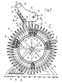
- FIG. 1 shows a collecting drum 12 which is rotatably mounted on a frame 10 and can be driven in rotation with a plurality of supports 14 which extend in the longitudinal direction of the collecting drum 12 and which together rotate in the direction of the arrow U around the axis of rotation 16.
- a plurality of supports 14 which extend in the longitudinal direction of the collecting drum 12 and which together rotate in the direction of the arrow U around the axis of rotation 16.
- ten schematically illustrated feed conveyors 18 are provided, spaced apart from one another in the direction of the axis of rotation 16, which can be driven synchronously by means of a common drive shaft 20.
- a conveyor 22 In one end region of the collecting drum 12 (at the end in the direction of the arrow F) there is a conveyor 22 which is also only shown schematically.
- the structure and mode of operation of such infeed and outfeed conveyors 18, 22 are generally known and are described, for example, in DE-OS 36 20 945 and the corresponding US Pat. No. 4,684,116.
- the feed conveyors 18 transport folded printed sheets 24 to the collecting drum 12, where they are opened by means of an opening device 26, also indicated only schematically, and placed by the feed conveyors 18 on the supports 14 of the collecting drum 12 or on the printed sheets 24 located thereon.
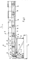
- the collecting drum 12 is shown in a vertical section.
- the collecting drum 12 has spoke wheels 28, only one of which is indicated by dashed lines in this figure.
- These spoke wheels 28 are rotatably mounted on a hollow axis 30 which is held by the frame 10 and whose longitudinal axis coincides with the circumferential axis 16 (FIG. 1).
- Arranged on the rings 32 of the spoke wheels 28 are C-shaped rails 34 which run in the axial direction and are spaced apart from one another in the circumferential direction. Seen in the radial direction, a saddle-shaped support 14 is attached to the outside of each rail 34.
- Carriages 36 are guided in each rail 34, only some of these carriages 36 being shown in FIG. 2. These cars 36 are described in more detail below. For the moment, it is sufficient to know that each of these carriages has clamping tongues 38, which can be moved from an open position into a closed position and vice versa by means of a control device 40.
- each bracket 42 In each case two carriages 36 running in adjacent rails 34 are coupled to one another in pairs by means of a bracket 42.
- a driver 44 Arranged on each bracket 42, seen in the radial direction, is a driver 44 protruding towards the inside, which is guided in a control link 46, which is provided on the lateral surface of a control cylinder 48, spaced from the rails 34 in the radial direction, from the rails 34.
- the control cylinder 48 is arranged in a rotationally fixed manner on the normally stationary hollow axis 30.
- a sprocket 49 is fastened to the spoke wheel 28, which is extremely provided against the direction of the arrow F (see FIG. 1), and is operatively connected to a gear 50 fastened to the frame 10 by means of a chain drive 52 indicated by dash-dotted lines.
- the transmission 50 is driven by a drive motor 54, which is also fastened to the frame 10, by means of a further chain drive 56, also indicated by dash-dotted lines.
- the feed conveyor 18 has an endless, dash-dotted drawing element 60 guided in guides 58, on which individually controllable grippers 62 are provided at fixed intervals.
- the traction element 60 is guided around a drive pulley 64 fastened to the drive shaft 20, by means of which the traction element 60 can be driven in the direction of the arrow Z.
- Each gripper 62 guided to the collecting drum 12 holds a printed sheet 24 at its fold 66.
- the ends 68 of the printed sheets 24, which are opposite to the fold 66 and hang freely downward, run onto a guide plate 70 of the opening device 26, so that the ends 68 lead to the fold 66.
- a rotatable, driven opening roller 72 with controllable clamps 74 is provided at the end of the guide plate 70.
- the end 68 of the printed sheet half 76 which slides on the guide plate 70 is gripped by a clamp 74 and bent against the outer surface of the opening roller 72 so that the two printed sheet halves 76 separate from one another at least in the region of the ends 68 and thus the printed sheet 24 is opened.
- a support 14 is inserted into an open printed sheet 24, the respective clamp 74 releases the end 68 of the printed sheet half 76 held by it, so that each printed sheet half 76 on each side of the support 14 comes to rest.
- the clamping tongues 38 located in the upper area of the collecting drum 12 are in the open position, as indicated in the area labeled A.
- the clamping tongues 38 are moved into their clamping position by means of the control device 40, which remains in place when the lower half C of the orbit is passed through.
- the clamping tongues 38 are then brought back into their open position.
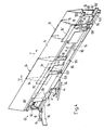
- FIG. 3 shows part of the collecting drum 12 in a section along the line III-III of FIG. 2.
- the one spoked wheel 28 visible in FIG. 3 is rotatably mounted on the hollow shaft 30, and the sprocket 49 of the chain drive 52 sits on its hub 78 in a rotationally fixed manner (see FIG. 2).
- the cross-sectionally C-shaped rail 34 on which the support 14 is seated, is fastened to the ring 32.
- Three carriages 36 visible in this figure and connected to one another by means of coupling members 82, are guided in the rail 34.
- Each carriage 36 has three or two pairs of guide rollers 84 which are rotatably mounted on it and which run in the rail 34.
- two clamping tongues 38 are pivotably mounted, which can be transferred from their open position to the closed position and back by means of rail pieces 86 of the control device 40 (see FIG. 2) which are coupled to one another.
- each rail piece 86 is mounted on two pivot levers 88, which in turn are pivotably mounted on the rail 34 and are aligned parallel to one another.
- 3 at the left end of the collecting drum 12 and designated 88 'pivoting lever is designed as an angle lever and is connected via a connecting rod 90 with one arm of a pivotally mounted on the collar 32, two-armed control lever 92, on the other arm a follower roller 94 is rotatably mounted, which in turn rolls on a guide surface of a fixed link 96.
- One at one end attached to the rail 34 and the other on the pivot lever 88 'acting compression spring 98 presses the follower 94 against the guide surface of the link 96 and at the same time pretensions the clamping tongues 38 against the open position.
- Folded printed sheets 24, fed by the feed conveyors 18 (see FIG. 1) and held by the clamping tongues 38, are indicated by dash-dotted lines, with a single printed sheet 24 opening at the first clamping tongue 38 as seen in the conveying direction F, starting from the left the support 14 rests, with the second clamping tongue 38 there are two congruent printing sheets 24 lying one above the other, with the third clamping tongue 38 there are three etc.
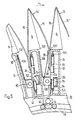
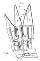
- FIG. 4 shows part of the left half of FIG. 3 in perspective and on an enlarged scale, the carriage 36 being shown partially cut away.
- the same parts are given the same reference numerals as in FIG. 3. It is only dealt with to the extent necessary for the understanding of FIG. 4 is.
- the opposite ends of the C-shaped rail 34 each carry a guide profile 100, for example made of plastic.
- the rollers of the guide roller pairs 84, which are rotatably mounted on the carriage 36, are concave, so that they partially encompass the guide profile 100 and give the carriage 36 a secure hold in a direction perpendicular to the rail 34.
- the pivot levers 88, 88 ' are pivotally mounted, the free ends of which are pivotally connected to the rail section 86.
- the rail piece 86 is also C-shaped in cross section, the upper flank 86 'being excluded in the region of the pivot lever 88. With 102 a connection piece is designated, which connects the rail piece 86 with the next following rail piece 86 seen in direction F (see FIG. 3).
- the rail piece 86 makes a movement like the coupling of a parallel crank mechanism and thus also a lifting movement in the direction of arrow H (in the radial direction towards the outside).
- This movement of the rail piece 86 is controlled by the follower roller 94 sliding on the link 96, the movement of which is transmitted by means of the control lever 92 and the connecting rod 90 to the pivot lever 88 'designed as an angle lever.
- the carriage 36 has a flat wall element 104 on which the pairs of guide rollers 84 are mounted.
- an upwardly angled guide element 106 which forms a pocket with a bottom and which is cut out in the region of the clamping tongues 38.
- the clamp tongues 38 which are preferably made of spring steel, are fastened to a shaft 110 which runs in the longitudinal direction of the rail 34 and is pivotably mounted on the wall element 104 by means of bearing elements 108 and which runs below the bottom of the guide element 106.
- the free ends of the clamping tongues 38 projecting upwards can carry clamping supports, for example made of rubber.
- a lever arm 112 protruding against the rail section 86 is fastened to the shaft 110, on the free end of which a roller 114 guided in the C-shaped rail section 86 is rotatably mounted.
- each support 14 of the collecting drum 12, together with the rail 34, carriage 36 and control device 40 assigned to it, has the same structure as the support 14 shown in FIGS. 3 and 4.
- FIG. 5 shows a section along the line VV of FIG. 3 through a plurality of supports 14 of the collecting drum 12, the supports 14 being located in region B of FIG. 2.
- the rails 34 are fastened on the rim 32 of the spoke wheel 28 (see FIGS. 2 and 3), and the saddle-shaped supports 14 are seated on them in the radial direction towards the outside.
- the guide profiles 100 are arranged on the mutually directed ends of the rails 34, on which the guide roller pairs 84 of the carriage 36 are guided.
- the pairs of guide rollers 84 are rotatably mounted on the wall element 104, and on this the guide element 106 and the bearing elements 108, of which only one of each carriage 36 is visible in FIG. 5, are fastened.
- the upper end of the guide element 106 extends behind the leading edge 109 of the trailing support 14.
- the upper end of the wall element 104 is covered by the trailing edge 109 'of the corresponding support 14, so that the ends 68 of the printed sheets 24 can easily reach the area of the clamping tongues 38 when placed on the supports 14.
- the clamping tongues 38 are fastened to the shaft 110 mounted on the bearing elements 108, of which the lever arm 112 protrudes against the rail piece 86.
- the roller 114 is rotatably mounted, which is guided in the rail piece 86 and has a convex tread. In this Figure 5, the suspension and actuator for the rail piece 86 is not shown.
- the rail piece 86 shown on the left in FIG. 5 is located in the direction of arrow H in the upper end position in the radial direction, so that the relevant clamping tongues 38 are in their open position, in which the free ends of the clamping tongues 38 are seen in the direction of rotation U. , come to rest behind the guide element 106 and the clamping tongues 38 are covered by the guide element 106.
- the rail piece 86 shown on the right in this figure is located opposite the arrow direction H in the lower, in the radial direction inner end position, whereby the corresponding clamping tongues 38 are transferred to the closed position in which they the printed sheet halves 76, 76 'between them and the wall element Clamp 104 counter stop formed.
- each pad 14 a single sheet 24 rests astride and each clamping tongue 38 clamps the sheet halves 76, 76 'of two different sheets 24, namely the trailing sheet half 76 of the leading sheet 24 and the leading sheet half 76' of the this trailing sheet 24 in each case.
- the two carriages 36 shown in FIG. 5 are operatively connected to one another by means of the bracket 42, but the rail sections 86 can be controlled independently of one another.
- the driver 44 has a roller which is guided on two round profiles which have a circular cross section and are arranged on the control cylinder 48 in parallel, the surfaces of which are directed towards one another and form the control link 46.
- the coupling members are designated, by means of which the carriages 36 guided in a rail 34 are coupled to one another.
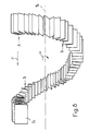
- Fig. 6 shows the same section as Fig. 5, but on each pad 14 two astride superimposed sheets 24, 24 'are stored and the pads 14 are in area D of Fig. 2.
- the clamping tongues 38 leading in the direction of rotation U are in their open position, since the rail piece 86 in question, viewed in the direction of the arrow H, is in its upper end position in the radial direction. Due to the dead weight of the printed sheet halves 76, 76 ', these now rest on the guide element 106.
- the rear clamping tongues 38 seen in the direction of rotation U are still in their closed position and clamp between themselves and the wall element 104 the trailing or leading sheet halves 76, 76 'of two superimposed sheets 24, 24' fixed.
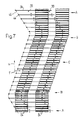
- FIG. 7 shows the collecting process schematically, simplified, with the aid of a processing, only the area of the first two feed conveyors 18 (FIG. 1) being shown.
- the development of the control link 46 is indicated by a dash-dotted line labeled 46.
- the drivers 44 guided in the control link 46 are indicated with points, each driver 44 displacing the carriages 36 from two successive supports 14 (see also FIGS. 5 and 6).
- the lines denoted by 36 symbolize the carriages of every second edition 14. Only one carriage per edition 14 with two clamping tongues 38 is shown.
- the direction of rotation is indicated by U and the direction of the delivery stroke by F.
- the arrows labeled A to D refer to the areas indicated by the same letters in FIG. 2.
- the device according to FIGS. 1 to 7 functions as follows: As can be seen particularly from FIG. 2, the collecting drum 12 is driven in the direction of rotation U by means of the drive motor 54. The drivers 44 run in the control link 46 of the control cylinder 48. Since this control cylinder 48 is stationary, the carriages 36 now make a conveying and a return stroke in the direction of arrow F in the course of one revolution (see FIG. 7). The distance covered in one direction is slightly larger than the distance between two feed conveyors 18 in each case.
- the control cylinder 48 is positioned in such a way that the carriages 36 perform the return stroke in the direction of the arrow F and the lower half (between B and D) the conveying stroke in the direction of the arrow F essentially as the upper half (between D and B) of the circulation path passes through, it should be noted that the clamping tongues 38 are in the open position during the entire return stroke.
- an open printed sheet 24 is straddled by the first feed conveyor 18 in the direction of arrow F on each support 14, while the corresponding carriages 36 with opened clamping tongues 38 pass under the printed sheet 24 in the return stroke are located.
- the printed sheets 24 are not influenced by the carriages 36 during their return stroke, because all parts of the carriages 36 are set back with respect to the saddle-shaped supports 14 or are arranged inwards in the radial direction.
- the trailing sheet halves 76 and the leading sheet halves 76 'of the respective rear sheet 24 seen in the direction of arrow U lie against the wall elements 104 of the carriage 36 (see also Fig 5).
- the clamping tongues 38 of all of the carriages 36 assigned to a support 14 are then moved together from their open position into the closed position.
- the clamping tongues 38 may only be moved into the closed position if they have the same speed, as seen in the direction of the arrow F, as the printing sheets 24 already held by the leading clamping tongues 38 are taken earlier in the direction of arrow F in time than the trailing printed sheets 24 by the respective leading printed sheets 24, these printed sheets 24 are offset from one another, as is particularly shown in FIGS. 4 and 7. From the printed sheets 24, a zigzag-shaped snake is thus formed, in which two adjacent printed sheets 24 are offset from one another in the direction of arrow F.
- clamping tongues 38 are opened before the carriages 36 in question are braked in order to start their return stroke; the clamping tongues 38 of the carriage 36 in question may therefore only be in the closed position as long as the drivers 44 of this carriage 36 are in the area of the control link 46 with a constant slope (cf. FIG. 3).
- the direction of rotation is indicated by U and the direction of the delivery stroke by F. It should be noted that between the points labeled A and B the side edges of the printed sheets 24 are aligned with one another and thus do not experience any displacement in the direction of the conveying stroke F. At the points marked B, the printed sheets 24 are shifted against each other in the direction of the arrow F, and this shift remains until the point marked D, where this shift is then canceled again.
- the collecting drum 12 can be composed of sections as seen in the direction of the arrow F (see FIG. 1).
- a base section advantageously has the width of three processing stations (two feed conveyors 18 and one removal conveyor 20). Sections of the width of, for example, one or two processing stations (feed conveyor 18) can be attached or inserted into or into this basic section. Depending on the number of operations to be performed, e.g. the number of sheets 24, 24 'to be stacked, assemble such sections to form a collecting drum 12 of greater length.
- the carriages 36 and rail pieces 86 assigned to each support 14 can be coupled together by means of coupling members 82 or connecting pieces 102 in order to be moved together.
- the pads 14 are of course composed of sections of appropriate length.
- a single carriage 36 can be provided per support 14, which has more than two clamping tongues 38.
- each sheet 24, 24 ' is held by more than one clamping tongue 38 on a sheet half 76, 76'. It is also conceivable that each feed conveyor 18 feeds a plurality of printed sheets 24 arranged one inside the other.
- the hollow axis 30 together with the control cylinder 48 and / or the link 96 can be arranged to be pivotable about the circumferential axis 16 in order to prevent the movement of the carriages 36 or the clamping tongues 38 independently of the respective geometry of the feed and removal conveyors 18 , 22 and the size of the printed sheets 24, 24 'to be adjusted.
- the link 96 can be designed such that its guide surface can be changed, or it can be exchanged with another link 96 in order to adapt the locations of the closing or opening movement of the clamping tongues 38.
- the rail pieces 86 can, for example, also be L-shaped, in particular if the lever arms 112 are pretensioned in a pivoting direction and the rollers 114 press against one flank of the rail pieces 86.
- the movement of the rail pieces 86 can also take place in a direction other than in the radial direction H;
- feed conveyor 18 could be replaced by known feeders, which feed the printed sheets 24, 24 'to the editions.
Priority Applications (1)
| Application Number | Priority Date | Filing Date | Title |
|---|---|---|---|
| AT89106113T ATE85028T1 (de) | 1988-05-11 | 1989-04-07 | Einrichtung zum sammeln von gefalzten druckbogen. |
Applications Claiming Priority (2)
| Application Number | Priority Date | Filing Date | Title |
|---|---|---|---|
| CH1795/88 | 1988-05-11 | ||
| CH179588 | 1988-05-11 |
Publications (3)
| Publication Number | Publication Date |
|---|---|
| EP0341425A2 true EP0341425A2 (fr) | 1989-11-15 |
| EP0341425A3 EP0341425A3 (en) | 1990-07-04 |
| EP0341425B1 EP0341425B1 (fr) | 1993-01-27 |
Family
ID=4218772
Family Applications (1)
| Application Number | Title | Priority Date | Filing Date |
|---|---|---|---|
| EP89106113A Expired - Lifetime EP0341425B1 (fr) | 1988-05-11 | 1989-04-07 | Dispositif pour collationner des produits imprimés pliés |
Country Status (11)
| Country | Link |
|---|---|
| US (1) | US5052667A (fr) |
| EP (1) | EP0341425B1 (fr) |
| JP (1) | JP2649414B2 (fr) |
| AT (1) | ATE85028T1 (fr) |
| AU (1) | AU603513B2 (fr) |
| CA (1) | CA1332432C (fr) |
| DD (1) | DD287463A5 (fr) |
| DE (1) | DE58903379D1 (fr) |
| ES (1) | ES2037312T3 (fr) |
| FI (1) | FI93098C (fr) |
| RU (1) | RU2052372C1 (fr) |
Cited By (10)
| Publication number | Priority date | Publication date | Assignee | Title |
|---|---|---|---|---|
| EP0409770A2 (fr) * | 1989-07-21 | 1991-01-23 | Ferag AG | Réunion des parties de produits imprimés |
| EP0518063A1 (fr) * | 1991-06-10 | 1992-12-16 | Ferag AG | Procédé et dispositif pour ouvrir et pour déposer sur un support en forme de selle des produits pliés d'imprimerie |
| EP0550828A1 (fr) * | 1992-01-10 | 1993-07-14 | Ferag AG | Procédé et dispositif de traitement de produits imprimés |
| EP0662440A1 (fr) * | 1994-01-10 | 1995-07-12 | Ferag AG | Dispositif pour l'agrafage par adhésif de produits imprimés |
| EP0672603A1 (fr) * | 1994-03-08 | 1995-09-20 | Ferag AG | Dispositif pour réaliser des imprimés composés |
| EP0681979A1 (fr) * | 1994-04-28 | 1995-11-15 | Ferag AG | Dispositif pour traiter des produits imprimés |
| EP0685420A1 (fr) | 1994-06-03 | 1995-12-06 | Ferag AG | Procédé de contrôle pour la fabrication de produits imprimés et ensemble pour la mise en oeuvre du procédé |
| EP0709218A1 (fr) | 1994-10-27 | 1996-05-01 | Ferag AG | Procédé et dispositif pour marquer des produits imprimés |
| EP1990301A1 (fr) | 2007-05-11 | 2008-11-12 | Ferag AG | Dispositif de traitement modulaire et kit de montage d'un tel dispositif de traitement |
| US8424861B2 (en) | 2007-10-18 | 2013-04-23 | Ferag Ag | Apparatus and method for the production of multi-piece printed products |
Families Citing this family (20)
| Publication number | Priority date | Publication date | Assignee | Title |
|---|---|---|---|---|
| ATE72555T1 (de) * | 1988-05-11 | 1992-02-15 | Ferag Ag | Einrichtung zum zusammentragen, einstecken und sammeln von druckereiprodukten. |
| EP0518064B1 (fr) * | 1991-06-10 | 1995-11-15 | Ferag AG | Procédé et appareil pour la manutention de produits imprimés |
| EP0522319B1 (fr) * | 1991-07-11 | 1995-02-01 | Ferag AG | Procédé et dispositif pour ouvrir des articles flexible pliés hors du centre |
| US5275685A (en) * | 1991-11-07 | 1994-01-04 | Ferag Ag | Apparatus for gluing attachment slips to printed products |
| DE59305872D1 (de) * | 1993-01-11 | 1997-04-24 | Ferag Ag | Sammelhefter für aus gefalteten Druckbogen bestehende Druckprodukte |
| DE59405887D1 (de) * | 1993-10-08 | 1998-06-10 | Ferag Ag | Vorrichtung zum Oeffnen und Weitertransportieren von Druckereiprodukten |
| ES2098854T3 (es) * | 1994-01-19 | 1997-05-01 | Ferag Ag | Procedimiento y dispositivo para la encuadernacion con adhesivo de los pliegos de un producto de imprenta plegado de multiples paginas. |
| ES2110790T3 (es) * | 1994-03-24 | 1998-02-16 | Ferag Ag | Dispositivo para la aportacion de productos planos a un dispositivo de transformacion de productos de imprenta. |
| ES2121250T3 (es) * | 1994-05-04 | 1998-11-16 | Ferag Ag | Procedimiento para el tratamiento de articulos impresos. |
| CH687459A5 (de) * | 1994-06-23 | 1996-12-13 | Ferag Ag | Verfahren und Vorrichtung zum Sammeln von Druckereiprodukten. |
| CH690576A5 (de) * | 1995-06-30 | 2000-10-31 | Ferag Ag | Vorrichtung zum Verarbeiten von Druckereiprodukten. |
| CH689864A5 (de) * | 1995-06-30 | 1999-12-31 | Ferag Ag | Vorrichtung zum Verarbeiten von Druckereiprodukten. |
| DE59608549D1 (de) * | 1995-07-11 | 2002-02-14 | Ferag Ag | Vorrichtung zum Beschneiden von gefalteten Druckereierzeugnissen, wie Zeitungen, Zeitschriften, Broschüren und dergleichen |
| CH691058A5 (de) * | 1995-11-01 | 2001-04-12 | Grapha Holding Ag | Vorrichtung zum Verarbeiten gefalzter Druckbogen. |
| DK1050499T3 (da) | 1999-05-07 | 2003-12-08 | Ferag Ag | Device for feeding flat objects to a processing apparatus |
| DE10034150C1 (de) * | 2000-07-13 | 2002-01-24 | Roland Man Druckmasch | Vorrichtung zur Produktzusammenführung für doppelten 3. Falz an Druckmaschinen |
| US7033123B2 (en) * | 2002-02-28 | 2006-04-25 | Hewlett-Packard Development Company, L.P. | Booklet maker |
| US6981830B2 (en) * | 2002-02-28 | 2006-01-03 | Hewlett-Packard Development Company, L.P. | Pivotable collecting device |
| ATE468291T1 (de) * | 2006-03-10 | 2010-06-15 | Ferag Ag | Verfahren und einrichtung zum zuführen, öffnen und ablegen von gefalteten druckprodukten |
| US8602406B2 (en) * | 2010-05-28 | 2013-12-10 | Goss International Americas, Inc. | Signature transport device with rotary arm and method |
Citations (2)
| Publication number | Priority date | Publication date | Assignee | Title |
|---|---|---|---|---|
| DE3616566A1 (de) * | 1985-06-04 | 1986-12-04 | Grapha-Holding Ag, Hergiswil | Sammelhefter |
| DE3620945A1 (de) * | 1985-07-01 | 1987-01-08 | Ferag Ag | Verfahren und vorrichtung zum sammeln von gefalzten druckbogen |
Family Cites Families (12)
| Publication number | Priority date | Publication date | Assignee | Title |
|---|---|---|---|---|
| CH584153A5 (fr) * | 1973-10-10 | 1977-01-31 | Ferag Ag | |
| CH575303A5 (fr) * | 1975-02-26 | 1976-05-14 | Ferag Ag | |
| CH641113A5 (en) * | 1979-06-15 | 1984-02-15 | Ferag Ag | Process and device for opening folded, bound or stapled multipage products, in particular printed products |
| CH644814A5 (de) * | 1980-01-08 | 1984-08-31 | Ferag Ag | Verfahren und vorrichtung zum oeffnen von gefalteten, gebundenen oder gehefteten mehrblaettrigen erzeugnissen, insbesondere druckprodukten. |
| CH645074A5 (de) * | 1980-03-11 | 1984-09-14 | Ferag Ag | Verfahren und vorrichtung zum bilden von mehrblaettrigen druckprodukten, insbesondere zeitungen und zeitschriften. |
| CH645073A5 (de) * | 1980-03-11 | 1984-09-14 | Ferag Ag | Verfahren und vorrichtung zum zusammentragen von blaettern bzw. bogen zu mehrblaettrigen druckprodukten, insbesondere zeitungen und zeitschriften. |
| EP0095603B1 (fr) * | 1982-06-01 | 1986-03-12 | Ferag AG | Dispositif d'assemblage de feuilles pliées d'imprimerie |
| DE3660669D1 (en) * | 1985-07-01 | 1988-10-13 | Ferag Ag | Method and device for opening eccentrically folded printing products |
| CH668245A5 (de) * | 1985-09-27 | 1988-12-15 | Ferag Ag | Einrichtung zum zusammentragen unterschiedlicher druckprodukte. |
| DE3760149D1 (en) * | 1986-02-14 | 1989-06-15 | Ferag Ag | Apparatus for processing printed products |
| ES2037311T3 (es) * | 1988-05-11 | 1993-06-16 | Ferag Ag | Dispositivo para la manipulacion de productos de imprenta. |
| ATE72555T1 (de) * | 1988-05-11 | 1992-02-15 | Ferag Ag | Einrichtung zum zusammentragen, einstecken und sammeln von druckereiprodukten. |
-
1989
- 1989-04-07 AT AT89106113T patent/ATE85028T1/de not_active IP Right Cessation
- 1989-04-07 EP EP89106113A patent/EP0341425B1/fr not_active Expired - Lifetime
- 1989-04-07 DE DE8989106113T patent/DE58903379D1/de not_active Expired - Lifetime
- 1989-04-07 ES ES198989106113T patent/ES2037312T3/es not_active Expired - Lifetime
- 1989-05-01 AU AU33919/89A patent/AU603513B2/en not_active Ceased
- 1989-05-09 US US07/349,303 patent/US5052667A/en not_active Expired - Fee Related
- 1989-05-09 DD DD89328421A patent/DD287463A5/de not_active IP Right Cessation
- 1989-05-10 JP JP1117178A patent/JP2649414B2/ja not_active Expired - Lifetime
- 1989-05-10 RU SU894614044A patent/RU2052372C1/ru active
- 1989-05-10 FI FI892269A patent/FI93098C/fi not_active IP Right Cessation
- 1989-05-10 CA CA000599201A patent/CA1332432C/fr not_active Expired - Fee Related
Patent Citations (2)
| Publication number | Priority date | Publication date | Assignee | Title |
|---|---|---|---|---|
| DE3616566A1 (de) * | 1985-06-04 | 1986-12-04 | Grapha-Holding Ag, Hergiswil | Sammelhefter |
| DE3620945A1 (de) * | 1985-07-01 | 1987-01-08 | Ferag Ag | Verfahren und vorrichtung zum sammeln von gefalzten druckbogen |
Cited By (14)
| Publication number | Priority date | Publication date | Assignee | Title |
|---|---|---|---|---|
| EP0409770A2 (fr) * | 1989-07-21 | 1991-01-23 | Ferag AG | Réunion des parties de produits imprimés |
| EP0409770A3 (en) * | 1989-07-21 | 1991-06-05 | Ferag Ag | Joining together of printed products components |
| US5137409A (en) * | 1989-07-21 | 1992-08-11 | Ferag Ag | Joining together of printed partial products |
| US5193851A (en) * | 1989-07-21 | 1993-03-16 | Ferag Ag | Joining printed partial products together |
| EP0518063A1 (fr) * | 1991-06-10 | 1992-12-16 | Ferag AG | Procédé et dispositif pour ouvrir et pour déposer sur un support en forme de selle des produits pliés d'imprimerie |
| EP0550828A1 (fr) * | 1992-01-10 | 1993-07-14 | Ferag AG | Procédé et dispositif de traitement de produits imprimés |
| EP0662440A1 (fr) * | 1994-01-10 | 1995-07-12 | Ferag AG | Dispositif pour l'agrafage par adhésif de produits imprimés |
| EP0672603A1 (fr) * | 1994-03-08 | 1995-09-20 | Ferag AG | Dispositif pour réaliser des imprimés composés |
| EP0681979A1 (fr) * | 1994-04-28 | 1995-11-15 | Ferag AG | Dispositif pour traiter des produits imprimés |
| EP0685420A1 (fr) | 1994-06-03 | 1995-12-06 | Ferag AG | Procédé de contrôle pour la fabrication de produits imprimés et ensemble pour la mise en oeuvre du procédé |
| EP0709218A1 (fr) | 1994-10-27 | 1996-05-01 | Ferag AG | Procédé et dispositif pour marquer des produits imprimés |
| EP1990301A1 (fr) | 2007-05-11 | 2008-11-12 | Ferag AG | Dispositif de traitement modulaire et kit de montage d'un tel dispositif de traitement |
| US7959144B2 (en) | 2007-05-11 | 2011-06-14 | Ferag Ag | Modular processing device as well as a construction kit for the construction of such a processing device |
| US8424861B2 (en) | 2007-10-18 | 2013-04-23 | Ferag Ag | Apparatus and method for the production of multi-piece printed products |
Also Published As
| Publication number | Publication date |
|---|---|
| CA1332432C (fr) | 1994-10-11 |
| FI93098C (fi) | 1995-02-27 |
| AU3391989A (en) | 1989-11-16 |
| DD287463A5 (de) | 1991-02-28 |
| JPH0238255A (ja) | 1990-02-07 |
| DE58903379D1 (de) | 1993-03-11 |
| FI892269A0 (fi) | 1989-05-10 |
| FI93098B (fi) | 1994-11-15 |
| AU603513B2 (en) | 1990-11-15 |
| ES2037312T3 (es) | 1993-06-16 |
| FI892269A (fi) | 1989-11-12 |
| EP0341425A3 (en) | 1990-07-04 |
| ATE85028T1 (de) | 1993-02-15 |
| EP0341425B1 (fr) | 1993-01-27 |
| JP2649414B2 (ja) | 1997-09-03 |
| RU2052372C1 (ru) | 1996-01-20 |
| US5052667A (en) | 1991-10-01 |
Similar Documents
| Publication | Publication Date | Title |
|---|---|---|
| EP0341425B1 (fr) | Dispositif pour collationner des produits imprimés pliés | |
| EP0341423B1 (fr) | Appareil pour l'assemblage, insertion et groupement de produits imprimés | |
| EP0341424B1 (fr) | Dispositif pour traiter des produits imprimés | |
| EP0550828B1 (fr) | Procédé et dispositif de traitement de produits imprimés | |
| DE2918621C2 (de) | Vorrichtung zum Transportieren von Vorformlingen aus Kunststoff zu einer Blasformmaschine | |
| DE3220495C2 (de) | Fördervorrichtung für Zuschnitte | |
| EP1944254B1 (fr) | Dispositif destiné au transport de produits d'impression | |
| EP0623542B1 (fr) | Dispositif pour empiler un chant de feuilles imprimées | |
| EP0675005B1 (fr) | Dispositif pour la reliure adhésive de produits imprimés | |
| CH690646A5 (de) | Vorrichtung zum Fördern von Gegenständen. | |
| EP0366038B1 (fr) | Dispositif pour plier en zigzag et empiler une bande de matériau | |
| EP0606550B1 (fr) | Dispositif pour transporter les objets plats à un dispositif de traitement de produit imprimé | |
| DE3620945A1 (de) | Verfahren und vorrichtung zum sammeln von gefalzten druckbogen | |
| EP0476718B1 (fr) | Dispositif pour piquer des produits d'imprimerie à plusieurs parties | |
| EP0510525B1 (fr) | Procédé et dispositif pour traiter des produits imprimés | |
| EP0606549A1 (fr) | Dispositif de transport d'objets plats | |
| CH680851A5 (fr) | ||
| EP0210494B1 (fr) | Dispositif de rassemblement pour feuilles pliées | |
| EP0218804B1 (fr) | Dispositif pour reprendre et transférer des feuilles pliées d'un dispositif de transport | |
| DE2935263A1 (de) | Automatische buchstapelmaschine | |
| DE1561141B2 (de) | Vorrichtung zum einfuehren von beilagen in gefaltete druckerzeugnisse | |
| DE10349668A1 (de) | Verfahren zum Transport von Bedruckstoffbögen und Bogentransportvorrichtung | |
| CH660578A5 (de) | Verfahren und einrichtung zur durchlaufhandhabung von blattfoermigen gegenstaenden. | |
| EP1418146B1 (fr) | Dispositif pour collecter et traiter des produits imprimés pliés | |
| EP2418164B1 (fr) | Procédé et dispositif d'assemblage de produits plats avec d'autres produits plats et dispositif de transport de produits plats, notamment de produits d'imprimerie |
Legal Events
| Date | Code | Title | Description |
|---|---|---|---|
| PUAI | Public reference made under article 153(3) epc to a published international application that has entered the european phase |
Free format text: ORIGINAL CODE: 0009012 |
|
| AK | Designated contracting states |
Kind code of ref document: A2 Designated state(s): AT BE CH DE ES FR GB IT LI NL SE |
|
| PUAL | Search report despatched |
Free format text: ORIGINAL CODE: 0009013 |
|
| AK | Designated contracting states |
Kind code of ref document: A3 Designated state(s): AT BE CH DE ES FR GB IT LI NL SE |
|
| 17P | Request for examination filed |
Effective date: 19900607 |
|
| 17Q | First examination report despatched |
Effective date: 19920115 |
|
| GRAA | (expected) grant |
Free format text: ORIGINAL CODE: 0009210 |
|
| AK | Designated contracting states |
Kind code of ref document: B1 Designated state(s): AT BE CH DE ES FR GB IT LI NL SE |
|
| REF | Corresponds to: |
Ref document number: 85028 Country of ref document: AT Date of ref document: 19930215 Kind code of ref document: T |
|
| REF | Corresponds to: |
Ref document number: 58903379 Country of ref document: DE Date of ref document: 19930311 |
|
| GBT | Gb: translation of ep patent filed (gb section 77(6)(a)/1977) |
Effective date: 19930223 |
|
| ET | Fr: translation filed | ||
| ITF | It: translation for a ep patent filed |
Owner name: SOCIETA' ITALIANA BREVETTI S.P.A. |
|
| REG | Reference to a national code |
Ref country code: ES Ref legal event code: FG2A Ref document number: 2037312 Country of ref document: ES Kind code of ref document: T3 |
|
| PLBE | No opposition filed within time limit |
Free format text: ORIGINAL CODE: 0009261 |
|
| STAA | Information on the status of an ep patent application or granted ep patent |
Free format text: STATUS: NO OPPOSITION FILED WITHIN TIME LIMIT |
|
| 26N | No opposition filed | ||
| EAL | Se: european patent in force in sweden |
Ref document number: 89106113.7 |
|
| PGFP | Annual fee paid to national office [announced via postgrant information from national office to epo] |
Ref country code: NL Payment date: 20000320 Year of fee payment: 12 |
|
| PGFP | Annual fee paid to national office [announced via postgrant information from national office to epo] |
Ref country code: AT Payment date: 20000322 Year of fee payment: 12 |
|
| PGFP | Annual fee paid to national office [announced via postgrant information from national office to epo] |
Ref country code: FR Payment date: 20000327 Year of fee payment: 12 |
|
| PGFP | Annual fee paid to national office [announced via postgrant information from national office to epo] |
Ref country code: BE Payment date: 20000405 Year of fee payment: 12 |
|
| PGFP | Annual fee paid to national office [announced via postgrant information from national office to epo] |
Ref country code: ES Payment date: 20000418 Year of fee payment: 12 |
|
| PGFP | Annual fee paid to national office [announced via postgrant information from national office to epo] |
Ref country code: GB Payment date: 20010316 Year of fee payment: 13 |
|
| PGFP | Annual fee paid to national office [announced via postgrant information from national office to epo] |
Ref country code: SE Payment date: 20010402 Year of fee payment: 13 |
|
| PG25 | Lapsed in a contracting state [announced via postgrant information from national office to epo] |
Ref country code: AT Free format text: LAPSE BECAUSE OF NON-PAYMENT OF DUE FEES Effective date: 20010407 |
|
| PG25 | Lapsed in a contracting state [announced via postgrant information from national office to epo] |
Ref country code: ES Free format text: LAPSE BECAUSE OF NON-PAYMENT OF DUE FEES Effective date: 20010409 |
|
| PG25 | Lapsed in a contracting state [announced via postgrant information from national office to epo] |
Ref country code: FR Free format text: THE PATENT HAS BEEN ANNULLED BY A DECISION OF A NATIONAL AUTHORITY Effective date: 20010430 Ref country code: BE Free format text: LAPSE BECAUSE OF NON-PAYMENT OF DUE FEES Effective date: 20010430 |
|
| BERE | Be: lapsed |
Owner name: FERAG A.G. Effective date: 20010430 |
|
| PG25 | Lapsed in a contracting state [announced via postgrant information from national office to epo] |
Ref country code: NL Free format text: LAPSE BECAUSE OF NON-PAYMENT OF DUE FEES Effective date: 20011101 |
|
| REG | Reference to a national code |
Ref country code: GB Ref legal event code: IF02 |
|
| NLV4 | Nl: lapsed or anulled due to non-payment of the annual fee |
Effective date: 20011101 |
|
| REG | Reference to a national code |
Ref country code: FR Ref legal event code: ST |
|
| PG25 | Lapsed in a contracting state [announced via postgrant information from national office to epo] |
Ref country code: GB Free format text: LAPSE BECAUSE OF NON-PAYMENT OF DUE FEES Effective date: 20020407 |
|
| PG25 | Lapsed in a contracting state [announced via postgrant information from national office to epo] |
Ref country code: SE Free format text: LAPSE BECAUSE OF NON-PAYMENT OF DUE FEES Effective date: 20020408 |
|
| EUG | Se: european patent has lapsed |
Ref document number: 89106113.7 |
|
| GBPC | Gb: european patent ceased through non-payment of renewal fee |
Effective date: 20020407 |
|
| REG | Reference to a national code |
Ref country code: ES Ref legal event code: FD2A Effective date: 20030203 |
|
| REG | Reference to a national code |
Ref country code: CH Ref legal event code: PFA Owner name: FERAG AG Free format text: FERAG AG#ZUERICHSTRASSE 74#8340 HINWIL (CH) -TRANSFER TO- FERAG AG#PATENTABTEILUNG Z. H. MARKUS FELIX ZUERICHSTRASSE 74#8340 HINWIL (CH) |
|
| PG25 | Lapsed in a contracting state [announced via postgrant information from national office to epo] |
Ref country code: IT Free format text: LAPSE BECAUSE OF NON-PAYMENT OF DUE FEES;WARNING: LAPSES OF ITALIAN PATENTS WITH EFFECTIVE DATE BEFORE 2007 MAY HAVE OCCURRED AT ANY TIME BEFORE 2007. THE CORRECT EFFECTIVE DATE MAY BE DIFFERENT FROM THE ONE RECORDED. Effective date: 20050407 |
|
| PGFP | Annual fee paid to national office [announced via postgrant information from national office to epo] |
Ref country code: CH Payment date: 20080424 Year of fee payment: 20 Ref country code: DE Payment date: 20080418 Year of fee payment: 20 |
|
| REG | Reference to a national code |
Ref country code: CH Ref legal event code: PL |