EP0806131A1 - Topfballenhandlung für Pflanzmaschine - Google Patents
Topfballenhandlung für Pflanzmaschine Download PDFInfo
- Publication number
- EP0806131A1 EP0806131A1 EP97104432A EP97104432A EP0806131A1 EP 0806131 A1 EP0806131 A1 EP 0806131A1 EP 97104432 A EP97104432 A EP 97104432A EP 97104432 A EP97104432 A EP 97104432A EP 0806131 A1 EP0806131 A1 EP 0806131A1
- Authority
- EP
- European Patent Office
- Prior art keywords
- seedling
- tray
- taking out
- transportation apparatus
- seedlings
- Prior art date
- Legal status (The legal status is an assumption and is not a legal conclusion. Google has not performed a legal analysis and makes no representation as to the accuracy of the status listed.)
- Granted
Links
- 238000002054 transplantation Methods 0.000 title claims abstract description 16
- 230000007246 mechanism Effects 0.000 claims description 35
- 230000000149 penetrating effect Effects 0.000 claims description 13
- 238000010899 nucleation Methods 0.000 claims 1
- 230000032258 transport Effects 0.000 abstract description 14
- 230000036544 posture Effects 0.000 description 4
- 238000010276 construction Methods 0.000 description 3
- 239000012530 fluid Substances 0.000 description 3
- 238000003780 insertion Methods 0.000 description 3
- 230000037431 insertion Effects 0.000 description 3
- PPBRXRYQALVLMV-UHFFFAOYSA-N Styrene Chemical compound C=CC1=CC=CC=C1 PPBRXRYQALVLMV-UHFFFAOYSA-N 0.000 description 2
- 230000007423 decrease Effects 0.000 description 2
- 230000035515 penetration Effects 0.000 description 2
- CYISMTMRBPPERU-UHFFFAOYSA-N CCC1CCC(C)CC1 Chemical compound CCC1CCC(C)CC1 CYISMTMRBPPERU-UHFFFAOYSA-N 0.000 description 1
- 238000010586 diagram Methods 0.000 description 1
- 238000007599 discharging Methods 0.000 description 1
- 239000000463 material Substances 0.000 description 1
- 239000011159 matrix material Substances 0.000 description 1
- 238000012986 modification Methods 0.000 description 1
- 230000004048 modification Effects 0.000 description 1
- 239000011347 resin Substances 0.000 description 1
- 229920005989 resin Polymers 0.000 description 1
- 238000005096 rolling process Methods 0.000 description 1
- 239000000126 substance Substances 0.000 description 1
Images


Classifications
-
- A—HUMAN NECESSITIES
- A01—AGRICULTURE; FORESTRY; ANIMAL HUSBANDRY; HUNTING; TRAPPING; FISHING
- A01C—PLANTING; SOWING; FERTILISING
- A01C11/00—Transplanting machines
- A01C11/02—Transplanting machines for seedlings
- A01C11/025—Transplanting machines using seedling trays; Devices for removing the seedlings from the trays
-
- A—HUMAN NECESSITIES
- A01—AGRICULTURE; FORESTRY; ANIMAL HUSBANDRY; HUNTING; TRAPPING; FISHING
- A01G—HORTICULTURE; CULTIVATION OF VEGETABLES, FLOWERS, RICE, FRUIT, VINES, HOPS OR SEAWEED; FORESTRY; WATERING
- A01G9/00—Cultivation in receptacles, forcing-frames or greenhouses; Edging for beds, lawn or the like
- A01G9/02—Receptacles, e.g. flower-pots or boxes; Glasses for cultivating flowers
- A01G9/029—Receptacles for seedlings
- A01G9/0299—Handling or transporting of soil blocks or seedlings
-
- Y—GENERAL TAGGING OF NEW TECHNOLOGICAL DEVELOPMENTS; GENERAL TAGGING OF CROSS-SECTIONAL TECHNOLOGIES SPANNING OVER SEVERAL SECTIONS OF THE IPC; TECHNICAL SUBJECTS COVERED BY FORMER USPC CROSS-REFERENCE ART COLLECTIONS [XRACs] AND DIGESTS
- Y10—TECHNICAL SUBJECTS COVERED BY FORMER USPC
- Y10S—TECHNICAL SUBJECTS COVERED BY FORMER USPC CROSS-REFERENCE ART COLLECTIONS [XRACs] AND DIGESTS
- Y10S47/00—Plant husbandry
- Y10S47/901—Plant container with flats, filling, planting, or conveying
Definitions
- This invention relates to a seedling transportation apparatus for a transplantation machine wherein a seedling taken out from a seedling tray transported horizontally is transported by a seedling carrying out conveyor disposed on the downstream side of the seedling tray in a transportation direction.
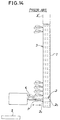
- FIG. 14 An exemplary one of such seedling transportation apparatus is shown in FIG. 14.
- the seedling transportation apparatus shown uses a seedling tray 3 wherein a tray body 1 formed from a foamed resin material or the like and having a generally plate like profile has a large number of seedling accommodating cells 2 formed therein such that each of them has a diameter which gradually decreases from an opening 2a to a bottom portion 2b thereof.
- the seedling transportation apparatus holds the seedling tray 3 uprightly such that the seedling accommodating cells 2 may extend horizontally as seen in FIG. 14.
- the seedling tray 3 is successively fed downwardly with a fixed pitch while seedlings P in the seedling accommodating cells 2 of the tray body 1 are successively taken out by a seedling taking out needle 4.
- the seedlings P taken out are successively transferred to a seedling carrying out conveyor 5 located sidewardly of the seedling tray 3.
- seedlings P In the seedling transportation apparatus, seedlings P must be taken out from the seedling tray 3 while the seedling tray 3 is kept uprightly. Further, in order to allow a new seedling tray 3' to be supplied, the seedling tray 3 from which all of the seedlings P have been taken out must be removed immediately.
- Another seedling transportation apparatus is constructed such that a seedling tray is transported along an inclined path, and at a predetermined position during the transportation, a seedling is taken out from the seedling tray. Then, the seedling tray from which seedlings are successively taken out is transported in a discharging direction while it is curved or bent gradually.
- a seedling transportation apparatus for a transplantation machine comprising a seedling taking out apparatus for taking out a seedling upwardly from a seedling tray having seedling accommodating cells in which seedlings are accommodated, a tray transportation apparatus having a horizontal transport path for transporting the seedling tray toward the seedling taking out apparatus, a seedling carrying out conveyor disposed at a location higher than the horizontal transport path of the tray transportation apparatus, and a transferring apparatus for transferring the seedling taken out by the seedling taking out apparatus onto the seedling carrying out conveyor.
- the tray transportation apparatus horizontally transports a seedling tray along the horizontal transport path thereof, and the seedling taking out apparatus takes out a seedling upwardly from the seedling tray which is in a horizontal condition. Then, the transferring apparatus transfers the seedling taken out by the seedling taking out apparatus onto the seedling carrying out conveyor disposed at a location higher than the horizontal transport path of the tray transportation apparatus.
- the seedling transportation apparatus of the present invention can transport a seedling tray, which has become emptied, to the downstream side as it is without removing it immediately to the outside of the transport path. Consequently, handling of a seedling tray from which seedlings have been removed to put the seedling tray into an empty condition is facilitated.
- the seedling taking out apparatus may include a seedling pushing out mechanism for pushing out a seedling upwardly from the seedling tray and a seedling holding mechanism for holding the seedling pushed out by the seedling pushing out mechanism.
- the transferring apparatus may move the seedling holding mechanism back and forth between a seedling penetrating position at which the seedling holding mechanism receives a seedling in a cell of the seedling tray and a seedling releasing position at which the seedling holding mechanism releases the received seedling toward the seedling carrying out conveyor.
- the seedling transportation apparatus for a transplantation machine may further comprise means defining a tray space formed on the downstream side of the tray transportation apparatus below the seedling carrying out conveyor.
- tray space is formed in this manner, seedling trays which have become emptied can be placed temporarily one on another in the tray space, and handling of seedling trays is further facilitated.
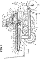
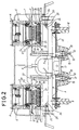
- FIGS. 1 and 2 there is shown a seedling transplantation machine on which a seedling transportation apparatus to which the present invention is applied is carried.
- the seedling transplantation machine shown includes a main frame 9 having pairs of upper and lower connection members 6 and 7 for connection to a tractor (not shown) formed on the front side thereof such that they project forwardly as seen in FIG. 2 and having a pair of driving wheels 8 provided on the rear side thereof, and a movable frame 11 mounted for upward and downward pivotal motion around a shaft 10 mounted horizontally at a front portion of the main frame 9.
- a pair of rolling coulters 12 for cutting disturbing substances
- a pair of openers 13 for forming furrows
- a pair of seedling planting wheels 14 (only one is shown in FIG.
- a pair of left and right seedling transportation apparatus A for supplying seedlings P to the seedling planting wheels 14, to which the present invention is applied, are carried on the movable frame 11.
- Each of the seedling transportation apparatus A includes a seedling taking out apparatus B for taking out seedlings P upwardly from a seedling tray T, a tray transportation apparatus C for transporting the seedling tray T horizontally toward the seedling taking out apparatus B, and a transferring apparatus E for transferring the seedlings P taken out by the seedling taking out apparatus B to a seedling carrying out conveyor D.
- the seedling taking out apparatus B, tray transportation apparatus C and transferring apparatus E are carried in an integrated relationship on a machine frame 16 mounted uprightly at a front portion of the movable frame 11.
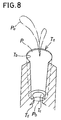
- the seedling tray T is generally in the form of a plate made of foamed styrene which cannot be bent during transportation, and has a plurality of seedling accommodating cells (hereinafter referred to simply as cells) Ta formed in a concave condition in a matrix having a pitch ⁇ equal in the perpendicular directions on a plane of the seedling tray T.
- Each of the cells Ta is formed such that the diameter thereof gradually decreases from an upper opening Tb to a bottom portion Td of the cell Ta, and has a rod insertion hole Tc formed in the bottom portion Td thereof.
- such seedling trays T are placed horizontally on the tray transportation apparatus C in an upright posture in which leaves Pa of seedlings P accommodated in the cells Ta thereof extend upwardly.
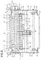
- the tray transportation apparatus C includes tray receiving rollers 17a to 17j arranged horizontally for individual rotation at predetermined distances such that two seedling trays T may be placed along upper edges of a pair of left and right base plates 18 between a location adjacent front ends 18a and another location adjacent rear ends 18b of the left and right base plates 18.
- a plurality of tray moving bars 20 for a moving seedling tray T are mounted horizontally in a predetermined spaced relationship from each other on a pair of left and right roller chains 19.
- the roller chains 19 extend along the tray receiving rollers 17a to 17j, and to this end, a pair of chain stretching shafts 21 and 22 are provided in parallel to each other on the front side with respect to the tray receiving roller 17a and the rear side with respect to the tray receiving roller 17j, respectively.
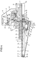
- a further chain stretching shaft 24 is mounted between a pair of left and right leg plates 23 of the left and right base plates 18 which extend downwardly below the tray receiving roller 17a as seen in FIGS. 3 to 6.
- Pairs of sprocket wheels 25 for keeping the roller chains 19 taut are secured at the opposite end portions of the chain stretching shafts 21, 22 and 24.
- a motor M1 is connected to the chain stretching shaft 21 via a roller chain 27 which extends between the motor M1 and a sprocket wheel 26 secured to an intermediate portion of the chain stretching shaft 21.
- the roller chains 19 are driven to move a seedling tray T toward the seedling taking out apparatus B. Consequently, the seedling tray T is pushed by one of the tray moving bars 20 so that it is moved toward a seedling taking out position R1 at which seedlings P are taken out from the seedling tray T by the seedling taking out apparatus B.
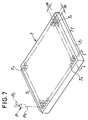
- a tray space SP is formed along the upper edges of the left and right base plates 18 adjacent the front ends 18a, that is, along a transport path of a seedling tray T below the seedling carrying out conveyor D, so that a seedling tray T may temporarily stay there.
- a seedling tray T after it is emptied as seedlings P are taken out therefrom at the seedling taking out position R1 is moved to the tray space SP.
- a seedling tray T moved by one of the tray moving bars 20 is moved toward the tray space SP while seedlings P are successively taken out therefrom at the seedling taking out position R1 such that, after those seedlings P accommodated in the last cell row Tn of the seedling tray T are taken out from the seedling tray T, the thus emptied seedling tray T stays in the tray space SP (refer to FIGS. 4 and 7).
- Driving of the tray transportation apparatus C is controlled by a driving control section F formed from a sequencer or the like.
- a rotary encoder EN (FIG. 6) connected to an end of the chain stretching shaft 21, a pair of tray detecting sensors S1 and S1' (FIGS. 5 and 6) provided at upper edge portions of the left and right base plates 18 on the rear side with respect to the chain stretching shaft 21 and a timing signal line TS from the seedling taking out apparatus B are connected to the input side of the driving control section F while the motor M1 is connected to the output side of the driving control section F (FIG. 9).
- the driving control section F has the following functions:
- the first cell row T1 of the seedling tray T stops at the seedling taking out position R1. Then, while the first cell row T1 stops there, a taking out operation of seedlings P by the seedling taking out apparatus B is performed.
- the driving control section F re-starts energization of the motor M1 to transport the seedling tray T again. Then, when the transport distance of the seedling tray T becomes coincident with the pitch ⁇ between the cells Ta formed on the seedling tray T again, the driving control section F stops energization of the motor M1 again so that the next cell row may be stopped at the seedling taking out position R1. The following cell rows are successively stopped at the seedling taking out position R1 in this manner.
- the seedling taking out apparatus B includes a seedling holding mechanism H which position seedling holding needles 42, which will be hereinafter described, serving as seedling holding elements in the proximity of the upper openings Tb of those cells Ta stopping at the seedling taking out position R1 for penetrating seedlings P pushed out from the cells Ta, and a seedling pushing out mechanism G for pushing out the seedlings P to be pushed out from the cells Ta until trailing ends Pb of the seedlings P move to the outside of the upper openings Tb.
- a seedling holding mechanism H which position seedling holding needles 42, which will be hereinafter described, serving as seedling holding elements in the proximity of the upper openings Tb of those cells Ta stopping at the seedling taking out position R1 for penetrating seedlings P pushed out from the cells Ta
- a seedling pushing out mechanism G for pushing out the seedlings P to be pushed out from the cells Ta until trailing ends Pb of the seedlings P move to the outside of the upper openings Tb.
- the seedling pushing out mechanism G includes a pair of pushing up arms 29 secured at base end portions thereof to a shaft 28 which is supported for rotation on and extends between the left and right base plates 18.
- a bracket 30 is secured to an intermediate portion of the shaft 28, and a driving rod K1a of a hydraulic or pneumatic fluid pressure cylinder K1 is connected to the bracket 30.
- the fluid pressure cylinder K1 is mounted by means of a bracket 31a on a connection pipe 31 extending horizontally between the left and right leg plates 23.
- a rod supporting member 33 having a plurality of seedling pushing out rods 32 formed uprightly thereon extends horizontally between end portions of the pushing up arms 29.
- the rod supporting member 33 has a pair of downwardly extending vertically elongated guide elements 35 formed on a lower face thereof, and a guide roller 34 is mounted for rotation at a lower end portion of each of the vertically elongated guide elements 35.
- a guide plate 36 having a pair of left and right bent lugs 36a is secured to the connection pipe 31, and a pair of arcuate guideways 36b for guiding the guide roller 34 are formed in the bent lugs 36a such that, when the guide roller 34 move along the arcuate guideways 36b, the seedling pushing out rods 32 may be moved upwardly and downwardly substantially in alignment with the seedling taking out position R1.
- each of the seedling pushing out rods 32 is a round bar member having a thickness with which it can be fitted in the rod insertion hole Tc of a cell Ta of a seedling tray T, and the seedling pushing out rods 32 are disposed in a row in the same pitch ⁇ as that of the cells Ta such that they are opposed to the cells Ta which make a row.
- the pushing up arms 29 are pivoted around the shaft 28 so that the free end portions thereof may move downwardly.
- the driving rod K1a is driven to contract, then the pushing up arms 29 are pivoted around the shaft 28 so that the free end portions thereof may move upwardly.
- the seedling pushing out rods 32 are moved back and forth between a pushing out start position R2 at which seedling contacting end faces 32a thereof are spaced downwardly from the rod insertion holes Tc of the opposing cells Ta and a pushing out end position R3 in which the seedling contacting end faces 32a project upwardly through the upper openings Tb of the opposing cells Ta (FIG. 10).
- the seedling holding mechanism H is supported by the transferring apparatus E, which will be hereinafter described in detail, such that seedling holding needles 42 for penetration into seedlings P to be pushed out from those cells Ta stopping at the seedling taking out position R1 may be movable back and forth between a seedling penetrating position R4 at which they are located in the proximity of the upper openings Tb of the cells Ta and a seedling releasing position R5 above the seedling carrying out conveyor D at which they transfer the seedlings P to the seedling carrying out conveyor D.
- the seedling holding mechanism H particularly when it moves the seedling holding needles 42 to the seedling penetrating position R4 will be described below with reference to FIGS. 10 to 13.
- a pair of left and right side plates 37 are supported for upward and downward pivotal motion at lower end portions of pivotal levers 65 of the transferring apparatus E by means of a pair of shafts 65a.
- a shaft 38 extends horizontally between front portions of the left and right side plates 37, and a pair of needle pulling in levers 40 are supported at base end portions thereof for pivotal motion on the shaft 38.
- a pair of tension springs 39 (only one is shown in FIGS. 10 and 11) extend between the needle pulling in levers 40 and the left and right side plates 37 (FIGS. 10, 11 and 13).
- a guide shaft 41 extends horizontally between end portions of the needle pulling in levers 40, and a needle supporting member 43 having a plurality of downwardly extending seedling holding needles 42 provided thereon is supported for pivotal motion on the guide shaft 41 via a bracket 44.
- a pair of guide rollers 45 (only one is shown in FIGS. 10 and 11) are mounted for rotation at a pair of bent lugs 44a of the bracket 44 via support pieces 46.
- the seedling holding needles 42 are moved upwardly and downwardly while keeping the downwardly extending postures thereof as the needle pulling in levers 40 are pivoted upwardly and downwardly around the shaft 38.
- the left and right side plates 37 have arcuate guideways 37a formed therein for guiding the guide shaft 41, and a pair of guide plates 47 in which arcuate guideways 47a for guiding the guide rollers 45 are formed in inner walls of the left and right side plates 37 (FIGS. 10, 11 and 13).
- a pair of hooks 48 for arresting the guide shaft 41 moved to a position at the lower ends of the arcuate guideways 37a are mounted for rotation on shafts 48a on outer faces of the left and right side plates 37.
- Each of the hooks 48 has a substantially L-shape in side elevation and has a guide shaft arresting portion 48b formed at one of a pair of legs thereof for arresting the guide shaft 41 while a spring mounting piece 48c to which an end of a coil spring 49 having the other end attached to a bent lug 37b of a corresponding one of the left and right side plates 37 is to be attached is formed at the other leg of the hook 48 (FIG. 12). Consequently, the hooks 48 are normally biased by the coil springs 49 in a direction in which the guide shaft arresting portions 48b thereof approach the guide shaft 41.
- the seedling holding needles 42 have a linear profile and located in pairs at intervals of the pitch ⁇ between the cells Ta of a seedling tray T in a row extending along a row of cells.
- a seedling releasing plate 50 is provided between lower end portions of the left and right side plates 37 and has formed therein needle loosely fitting holes 50a in which the seedling holding needles 42 are individually fitted loosely (FIGS. 10, 11 and 12).
- a pair of stoppers 51 for moving the guide shaft 41 of the seedling holding mechanism H moved to the seedling penetrating position R4 to the lower ends of the arcuate guideways 37a until the guide shaft 41 is arrested by the hooks 48, and a pair of arrest releasing members 52 having contacting rollers 52a for contacting with the hooks 48 of the seedling holding mechanism H moved to the seedling releasing position R5 to cancel the arrested condition of the guide shaft 41 by the hooks 48.
- the guide shaft 41 is arrested by the hooks 48, and consequently, the seedling holding needles 42 are held at pushed down positions in which the lower ends thereof are positioned in the proximity of the upper openings Tb of opposing cells Ta so that seedlings P which are pushed out from the cells Ta may be penetrated by the lower ends of the guide shaft 41 immediately after they start to be pushed out.
- Seedlings P in those cells Ta moved to the seedling taking out position R1 are penetrated and held by the seedling holding needles 42 of the seedling holding mechanism H at the seedling penetrating position R4 immediately after they start to be pushed out by the seedling pushing out rods 32, and as they are thereafter pushed out further by the seedling pushing out rods 32, they are penetrated gradually deeply by the seedling holding needles 42.
- the seedling pushing out rods 32 are moved to the pushing out end position R3, that is, when the trailing ends Pb of the seedlings P in the pushing out direction are pushed out to locations above the upper openings Tb of the cells Ta, the seedling holding needles 42 penetrate fully from the leading ends to the trailing ends Pb of the seedlings P in the pushing out direction (FIG. 10).
- the transferring apparatus E is constructed in the following manner.
- the left and right support plates 53 are provided uprightly on a pair of mounting frames 54 which are mounted between an upper end portion of the machine frame 16 and intermediate portions of the left and right base plates 18 such that they extend across the tray space SP (FIGS. 1 to 5).
- a connection plate 55 extends horizontally between upper end portions of the left and right support plates 53 and has support legs 56 to 58 extending downwardly from a lower face thereof.
- a support shaft 60 extends through and is supported for rotation on the support legs 56 to 58, and has a pair of brackets 59 secured at the opposite left and right ends thereof.
- a motor M2 is secured between the support legs 56 and 57, and a driving gear 62 is held in meshing engagement with a gear secured to a driving shaft of the motor M2.
- the driving gear 62 is secured to an inner end portion of a rotary shaft 63 which is supported for rotation on and extends horizontally between the support legs 56 and 57 (FIGS. 12 and 13).
- a lever supporting shaft 64 extends horizontally between front side upper end portions of the left and right support plates 53, and the pivotal levers 65 having the left and right side plates 37 of the seedling holding mechanism H supported for pivotal motion at lower end portions thereof are supported for pivotal motion at upper ends thereof on the lever supporting shaft 64.
- a connection member 66 extends horizontally between the pivotal levers 65, and a bracket 67 is provided at an intermediate portion of the connection member 66.
- a connection rod 68 is mounted for rotation at the opposite ends thereof on the bracket 67 and an eccentric mounting pin 62a provided projectingly and eccentrically on the driving gear 62.
- a small gear 69 is secured to a central portion of the support shaft 60 and is held in meshing engagement with the driving gear 62.
- a pair of support levers 71 are mounted at upper end portions thereof on the brackets 59 provided at the opposite left and right end portions of the support shaft 60, and the left and right side plates 37 of the seedling holding mechanism H are supported for pivotal motion on a shaft 70 extending horizontally between lower end portions of the support levers 71.
- the eccentric mounting pin 62a moves from the driving start position R6 toward the driving end position R7, whereupon the brackets 59 are pivoted upwardly.
- the left and right side plates 37 of the seedling holding mechanism H are acted upon by a force to pivot them upwardly around the shafts 65a of the pivotal levers 65. Consequently, the seedling holding mechanism H is pivoted upwardly by 90 degrees around the shafts 65a to a posture in which the seedling holding needles 42 extend horizontally, and is moved to the seedling releasing position R5 while keeping the posture.
- the seedling holding mechanism H moves back from the seedling releasing position R5 to seedling penetrating position R4 following the locus of movement described above reversely.
- the seedling carrying out conveyor D is supported above the tray space SP formed adjacent the front ends 18a of the left and right base plates 18, and a vertical conveyor 72 for transporting a seedling P toward the corresponding seedling planting wheel 14 is provided adjacent the last end of the seedling carrying out conveyor D in the carrying out direction.
- the seedling holding mechanism H is moved to the seedling penetrating position R4.
- seedling trays T are placed on the tray transportation apparatus C and a moving operation of them is started, then the seedling trays T are transported horizontally toward the seedling taking out apparatus B and a preceding one of them is stopped when the first cell row T1 thereof comes to the seedling taking out position R1.
- a pushing out operation for the seedlings P of the first cell row T1 of the seedling tray T is started by the seedling pushing out rods 32 of the seedling pushing out mechanism G so that the seedlings P are individually penetrated by the corresponding seedling holding needles 42 until they are held by the seedling holding needles 42.
- the seedling pushing out rods 32 are moved back to the pushing out start position R2, and the seedling holding mechanism H is moved from the seedling penetrating position R4 toward the seedling releasing position R5 while it is pivoted upwardly by 90 degrees around the shafts 65a.
- the seedlings P which have been penetrated by the seedling holding needles 42 are pulled out and released by the seedling releasing plate 50 and placed onto the seedling carrying out conveyor D therebelow.
- the seedlings P placed on the seedling carrying out conveyor D are thereafter transferred to the vertical conveyor 72 and transported toward the seedling planting wheel 14 by the vertical conveyor 72.
- the seedling holding mechanism H is moved back toward the seedling penetrating position R4, and the seedling pushing out rods 32 of the seedling pushing out mechanism G are moved back to the pushing out start position R2. Then, also the tray transportation apparatus C is driven to move the seedling tray T so that the next cell row may come to the seedling taking out position R1. Consequently, the seedling tray T is moved gradually into the tray space SP by the driving of the tray transportation apparatus C.
- the entire seedling tray T is moved to the tray space SP, in which it thereafter stays for a certain period of time.
- the tray space is constructed such that a single seedling tray T may temporarily stay therein, it may be constructed otherwise such that a seedling tray moved later may be placed on another seedling tray moved earlier so that several seedling trays may temporarily stay in a piled up condition in the tray space.
- the time until seedling trays staying in the tray space must be removed can be set comparatively long, and the seedling tray exchanging operation can be further moderated.
- the tray space for allowing a seedling tray to temporarily stay therein need not be formed, but upon transferring operation of seedlings to the seedling carrying out conveyor, a seedling tray may be moved successively to a location below the seedling carrying out conveyor.
Landscapes
- Life Sciences & Earth Sciences (AREA)
- Soil Sciences (AREA)
- Environmental Sciences (AREA)
- Transplanting Machines (AREA)
- Cultivation Receptacles Or Flower-Pots, Or Pots For Seedlings (AREA)
- Pretreatment Of Seeds And Plants (AREA)
- Agricultural Machines (AREA)
Applications Claiming Priority (3)
| Application Number | Priority Date | Filing Date | Title |
|---|---|---|---|
| JP139783/96 | 1996-05-10 | ||
| JP13978396 | 1996-05-10 | ||
| JP13978396A JP3215941B2 (ja) | 1996-05-10 | 1996-05-10 | 苗株搬送装置とその搬送方法 |
Publications (2)
| Publication Number | Publication Date |
|---|---|
| EP0806131A1 true EP0806131A1 (de) | 1997-11-12 |
| EP0806131B1 EP0806131B1 (de) | 2001-10-10 |
Family
ID=15253326
Family Applications (1)
| Application Number | Title | Priority Date | Filing Date |
|---|---|---|---|
| EP97104432A Expired - Lifetime EP0806131B1 (de) | 1996-05-10 | 1997-03-14 | Topfballenhandlung für Pflanzmaschine |
Country Status (8)
| Country | Link |
|---|---|
| US (1) | US5784984A (de) |
| EP (1) | EP0806131B1 (de) |
| JP (1) | JP3215941B2 (de) |
| AT (1) | ATE206580T1 (de) |
| DE (1) | DE69707193T2 (de) |
| DK (1) | DK0806131T3 (de) |
| ES (1) | ES2165539T3 (de) |
| PT (1) | PT806131E (de) |
Cited By (7)
| Publication number | Priority date | Publication date | Assignee | Title |
|---|---|---|---|---|
| EP0900516A1 (de) * | 1997-09-08 | 1999-03-10 | Circle Tekko Co., Ltd. | Verfahren und Einrichtung zur Aufnahme von Sämlingen aus einer Sämlingschale |
| WO2004095906A1 (en) | 2003-05-01 | 2004-11-11 | N.V. Agriplant | A method and apparatus for transporting seedlings in a planting machine |
| CN103125300A (zh) * | 2013-03-12 | 2013-06-05 | 阳曲县诚同茂业科技有限公司 | 联驱互串式育苗机组 |
| CN107624314A (zh) * | 2017-11-15 | 2018-01-26 | 河南科技大学 | 一种育苗移栽机用苗盘自动输送装置 |
| US10299428B2 (en) | 2014-10-31 | 2019-05-28 | Risutec Oy | Planting seedlings |
| CN110149969A (zh) * | 2019-06-25 | 2019-08-23 | 合肥流荇蓝色农业有限公司 | 一种移动苗床上苗配套装置及其使用方法 |
| US11039578B2 (en) * | 2016-06-17 | 2021-06-22 | Ellepot A/S | Apparatus and system for transporting a length of growth medium cut into pieces of suitable size into a propagation tray |
Families Citing this family (9)
| Publication number | Priority date | Publication date | Assignee | Title |
|---|---|---|---|---|
| USD783421S1 (en) | 2016-01-05 | 2017-04-11 | Van Belle Nursery Inc. | Seedling tray |
| BR112019011014B1 (pt) * | 2016-11-29 | 2023-02-07 | Tigercat Industries Inc | Aparelho para plantio de mudas |
| CN109348796B (zh) * | 2018-11-05 | 2021-12-07 | 华中农业大学 | 油菜基质块苗移栽装置 |
| CN109601080A (zh) * | 2019-01-21 | 2019-04-12 | 东北农业大学 | 一种插秧装置 |
| CN115104412A (zh) * | 2020-11-07 | 2022-09-27 | 孙景旺 | 一种农业机械用移栽装置的使用方法 |
| EP4277462A4 (de) * | 2021-01-15 | 2025-02-12 | Maui Greens, Inc. | System zur gartenbildung von pflanzengefässen |
| TWI810128B (zh) * | 2022-12-21 | 2023-07-21 | 國立中興大學 | 氣壓式穴盤之自動化播種裝置 |
| WO2025037270A1 (en) * | 2023-08-17 | 2025-02-20 | Fravizel - Equipamentos Metalomecânicos, S.A. | A movable assembly for automatically providing living plants for planting |
| EP4508965A1 (de) * | 2023-08-17 | 2025-02-19 | Fravizel - Equipamentos Metalomecânicos, S.A. | Modul zum zuführen von lebenden pflanzen, kit und system zur automatischen bereitstellung von lebenden pflanzen zum pflanzen |
Citations (5)
| Publication number | Priority date | Publication date | Assignee | Title |
|---|---|---|---|---|
| FR2447671A1 (fr) * | 1979-02-02 | 1980-08-29 | Serlachius Oy | Procede et dispositif pour l'approvisionnement de bacs a plants dans une machine a planter |
| GB2064933A (en) * | 1979-12-18 | 1981-06-24 | Illinois Tool Works | Plant transfer mechanisms |
| EP0243264A1 (de) * | 1986-04-23 | 1987-10-28 | Ateliers De Claire Fontaine | Pflanzmaschine und Verfahren zum pflanzen für Setzlinge in Topfballen |
| GB2260474A (en) * | 1991-09-11 | 1993-04-21 | Richard Anthony Chamberlain | Transplanting apparatus for seedlings |
| US5320649A (en) * | 1992-08-18 | 1994-06-14 | Holland James J | Plant transplant system |
Family Cites Families (9)
| Publication number | Priority date | Publication date | Assignee | Title |
|---|---|---|---|---|
| US4440101A (en) * | 1979-12-18 | 1984-04-03 | Illinois Tool Works Inc. | Plant transfer mechanism |
| GB8426656D0 (en) * | 1984-10-22 | 1984-11-28 | Chamberlain R A | Transplanter |
| US4644880A (en) * | 1985-02-22 | 1987-02-24 | Growers Transplanting, Inc. | Method and apparatus for transplanting corps |
| US4750439A (en) * | 1986-08-27 | 1988-06-14 | Bud Antle, Inc. | Planting finger assembly |
| FI84870C (fi) * | 1987-11-02 | 1992-02-10 | Laennen Tehtaat Oy | Foerfarande och anordning foer plantering av klumpplantor. |
| US5477791A (en) * | 1993-03-04 | 1995-12-26 | Yanmar Agricultural Equipment Co., Ltd. | Seedling planting apparatus |
| JPH07184419A (ja) * | 1993-12-28 | 1995-07-25 | Yanmar Agricult Equip Co Ltd | 野菜移植機の苗株取出方法 |
| JPH07184421A (ja) * | 1993-12-28 | 1995-07-25 | Yanmar Agricult Equip Co Ltd | 移植機のトレイ縦送り装置 |
| US5557881A (en) * | 1995-02-21 | 1996-09-24 | Bouldin; Floyd | Seedling transplanter |
-
1996
- 1996-05-10 JP JP13978396A patent/JP3215941B2/ja not_active Expired - Fee Related
-
1997
- 1997-03-14 EP EP97104432A patent/EP0806131B1/de not_active Expired - Lifetime
- 1997-03-14 PT PT97104432T patent/PT806131E/pt unknown
- 1997-03-14 AT AT97104432T patent/ATE206580T1/de not_active IP Right Cessation
- 1997-03-14 DE DE69707193T patent/DE69707193T2/de not_active Expired - Fee Related
- 1997-03-14 ES ES97104432T patent/ES2165539T3/es not_active Expired - Lifetime
- 1997-03-14 DK DK97104432T patent/DK0806131T3/da active
- 1997-03-14 US US08/818,546 patent/US5784984A/en not_active Expired - Lifetime
Patent Citations (5)
| Publication number | Priority date | Publication date | Assignee | Title |
|---|---|---|---|---|
| FR2447671A1 (fr) * | 1979-02-02 | 1980-08-29 | Serlachius Oy | Procede et dispositif pour l'approvisionnement de bacs a plants dans une machine a planter |
| GB2064933A (en) * | 1979-12-18 | 1981-06-24 | Illinois Tool Works | Plant transfer mechanisms |
| EP0243264A1 (de) * | 1986-04-23 | 1987-10-28 | Ateliers De Claire Fontaine | Pflanzmaschine und Verfahren zum pflanzen für Setzlinge in Topfballen |
| GB2260474A (en) * | 1991-09-11 | 1993-04-21 | Richard Anthony Chamberlain | Transplanting apparatus for seedlings |
| US5320649A (en) * | 1992-08-18 | 1994-06-14 | Holland James J | Plant transplant system |
Cited By (9)
| Publication number | Priority date | Publication date | Assignee | Title |
|---|---|---|---|---|
| EP0900516A1 (de) * | 1997-09-08 | 1999-03-10 | Circle Tekko Co., Ltd. | Verfahren und Einrichtung zur Aufnahme von Sämlingen aus einer Sämlingschale |
| WO2004095906A1 (en) | 2003-05-01 | 2004-11-11 | N.V. Agriplant | A method and apparatus for transporting seedlings in a planting machine |
| CN103125300A (zh) * | 2013-03-12 | 2013-06-05 | 阳曲县诚同茂业科技有限公司 | 联驱互串式育苗机组 |
| CN103125300B (zh) * | 2013-03-12 | 2014-04-02 | 阳曲县诚同茂业科技有限公司 | 联驱互串式育苗机组 |
| US10299428B2 (en) | 2014-10-31 | 2019-05-28 | Risutec Oy | Planting seedlings |
| US11039578B2 (en) * | 2016-06-17 | 2021-06-22 | Ellepot A/S | Apparatus and system for transporting a length of growth medium cut into pieces of suitable size into a propagation tray |
| CN107624314A (zh) * | 2017-11-15 | 2018-01-26 | 河南科技大学 | 一种育苗移栽机用苗盘自动输送装置 |
| CN107624314B (zh) * | 2017-11-15 | 2023-10-20 | 河南科技大学 | 一种育苗移栽机用苗盘自动输送装置 |
| CN110149969A (zh) * | 2019-06-25 | 2019-08-23 | 合肥流荇蓝色农业有限公司 | 一种移动苗床上苗配套装置及其使用方法 |
Also Published As
| Publication number | Publication date |
|---|---|
| DK0806131T3 (da) | 2001-11-19 |
| JP3215941B2 (ja) | 2001-10-09 |
| ATE206580T1 (de) | 2001-10-15 |
| JPH09298917A (ja) | 1997-11-25 |
| ES2165539T3 (es) | 2002-03-16 |
| PT806131E (pt) | 2002-01-30 |
| DE69707193T2 (de) | 2002-03-14 |
| EP0806131B1 (de) | 2001-10-10 |
| US5784984A (en) | 1998-07-28 |
| DE69707193D1 (de) | 2001-11-15 |
Similar Documents
| Publication | Publication Date | Title |
|---|---|---|
| US5784984A (en) | Seedling transportation apparatus for transplantation machine | |
| US6044778A (en) | Method and device for picking up seedlings from seedling tray | |
| DE69813114T2 (de) | Vorrichtung zur Selektion und zum Transport von Sämlingen in Erdballen und damit vorsorgte Verpflanzmaschine | |
| JP3750837B2 (ja) | 育苗容器段積装置 | |
| JPH09266707A (ja) | 苗株トレイの搬送方法とその装置 | |
| JP2860251B2 (ja) | 移植機用苗供給装置の葉挟み込み防止手段 | |
| JPS61231912A (ja) | 土付苗の列分離転載装置 | |
| JP2519843B2 (ja) | 土付苗の取出し方法及び取出し装置並びに土付苗送り装置 | |
| JP3384056B2 (ja) | 苗供給装置 | |
| JP2555229B2 (ja) | 移植機の苗送り装置 | |
| JP3147047B2 (ja) | 苗植機 | |
| JPS5915525A (ja) | 篠巻搬送マガジンの間欠送り装置 | |
| JP3369311B2 (ja) | 移植機 | |
| JPH09154328A (ja) | 移植機の苗トレイ押え装置 | |
| JP4100559B2 (ja) | 苗挿し機 | |
| JP3365740B2 (ja) | 移植機の苗トレイ送り装置 | |
| JP2803977B2 (ja) | 移植機のトレイ苗位置矯正機構 | |
| JPH0647209Y2 (ja) | 植付機の苗のせ台 | |
| JPS6242659Y2 (de) | ||
| JP3341375B2 (ja) | 苗移植機 | |
| JP3283696B2 (ja) | 移植機 | |
| JP2000270688A (ja) | 育苗マット充填装置 | |
| JP3203696B2 (ja) | 苗植機 | |
| JP3384047B2 (ja) | 移植機 | |
| JP2000116216A (ja) | 苗移植機 |
Legal Events
| Date | Code | Title | Description |
|---|---|---|---|
| PUAI | Public reference made under article 153(3) epc to a published international application that has entered the european phase |
Free format text: ORIGINAL CODE: 0009012 |
|
| AK | Designated contracting states |
Kind code of ref document: A1 Designated state(s): AT BE CH DE DK ES FI FR GB GR IE IT LI LU MC NL PT SE |
|
| 17P | Request for examination filed |
Effective date: 19980511 |
|
| 17Q | First examination report despatched |
Effective date: 20000214 |
|
| GRAG | Despatch of communication of intention to grant |
Free format text: ORIGINAL CODE: EPIDOS AGRA |
|
| GRAG | Despatch of communication of intention to grant |
Free format text: ORIGINAL CODE: EPIDOS AGRA |
|
| GRAH | Despatch of communication of intention to grant a patent |
Free format text: ORIGINAL CODE: EPIDOS IGRA |
|
| GRAH | Despatch of communication of intention to grant a patent |
Free format text: ORIGINAL CODE: EPIDOS IGRA |
|
| GRAA | (expected) grant |
Free format text: ORIGINAL CODE: 0009210 |
|
| AK | Designated contracting states |
Kind code of ref document: B1 Designated state(s): AT BE CH DE DK ES FI FR GB GR IE IT LI LU MC NL PT SE |
|
| REF | Corresponds to: |
Ref document number: 206580 Country of ref document: AT Date of ref document: 20011015 Kind code of ref document: T |
|
| REG | Reference to a national code |
Ref country code: CH Ref legal event code: NV Representative=s name: PA ALDO ROEMPLER Ref country code: CH Ref legal event code: EP |
|
| REG | Reference to a national code |
Ref country code: IE Ref legal event code: FG4D |
|
| REF | Corresponds to: |
Ref document number: 69707193 Country of ref document: DE Date of ref document: 20011115 |
|
| REG | Reference to a national code |
Ref country code: DK Ref legal event code: T3 |
|
| ET | Fr: translation filed | ||
| REG | Reference to a national code |
Ref country code: GB Ref legal event code: IF02 |
|
| REG | Reference to a national code |
Ref country code: PT Ref legal event code: SC4A Free format text: AVAILABILITY OF NATIONAL TRANSLATION Effective date: 20011031 |
|
| REG | Reference to a national code |
Ref country code: ES Ref legal event code: FG2A Ref document number: 2165539 Country of ref document: ES Kind code of ref document: T3 |
|
| REG | Reference to a national code |
Ref country code: GR Ref legal event code: EP Ref document number: 20010402636 Country of ref document: GR |
|
| PLBE | No opposition filed within time limit |
Free format text: ORIGINAL CODE: 0009261 |
|
| STAA | Information on the status of an ep patent application or granted ep patent |
Free format text: STATUS: NO OPPOSITION FILED WITHIN TIME LIMIT |
|
| 26N | No opposition filed | ||
| PGFP | Annual fee paid to national office [announced via postgrant information from national office to epo] |
Ref country code: MC Payment date: 20060322 Year of fee payment: 10 Ref country code: FI Payment date: 20060322 Year of fee payment: 10 |
|
| PGFP | Annual fee paid to national office [announced via postgrant information from national office to epo] |
Ref country code: GR Payment date: 20060323 Year of fee payment: 10 |
|
| PGFP | Annual fee paid to national office [announced via postgrant information from national office to epo] |
Ref country code: CH Payment date: 20060324 Year of fee payment: 10 |
|
| PGFP | Annual fee paid to national office [announced via postgrant information from national office to epo] |
Ref country code: DK Payment date: 20060328 Year of fee payment: 10 |
|
| PGFP | Annual fee paid to national office [announced via postgrant information from national office to epo] |
Ref country code: LU Payment date: 20060329 Year of fee payment: 10 |
|
| PG25 | Lapsed in a contracting state [announced via postgrant information from national office to epo] |
Ref country code: FI Free format text: LAPSE BECAUSE OF NON-PAYMENT OF DUE FEES Effective date: 20070314 |
|
| PG25 | Lapsed in a contracting state [announced via postgrant information from national office to epo] |
Ref country code: SE Free format text: LAPSE BECAUSE OF NON-PAYMENT OF DUE FEES Effective date: 20070315 |
|
| REG | Reference to a national code |
Ref country code: DK Ref legal event code: EBP |
|
| REG | Reference to a national code |
Ref country code: CH Ref legal event code: PL |
|
| EUG | Se: european patent has lapsed | ||
| PG25 | Lapsed in a contracting state [announced via postgrant information from national office to epo] |
Ref country code: MC Free format text: LAPSE BECAUSE OF NON-PAYMENT OF DUE FEES Effective date: 20070331 |
|
| PGFP | Annual fee paid to national office [announced via postgrant information from national office to epo] |
Ref country code: SE Payment date: 20060324 Year of fee payment: 10 |
|
| PG25 | Lapsed in a contracting state [announced via postgrant information from national office to epo] |
Ref country code: CH Free format text: LAPSE BECAUSE OF NON-PAYMENT OF DUE FEES Effective date: 20070331 Ref country code: LI Free format text: LAPSE BECAUSE OF NON-PAYMENT OF DUE FEES Effective date: 20070331 |
|
| PG25 | Lapsed in a contracting state [announced via postgrant information from national office to epo] |
Ref country code: DK Free format text: LAPSE BECAUSE OF NON-PAYMENT OF DUE FEES Effective date: 20070402 |
|
| PGFP | Annual fee paid to national office [announced via postgrant information from national office to epo] |
Ref country code: ES Payment date: 20080326 Year of fee payment: 12 |
|
| PGFP | Annual fee paid to national office [announced via postgrant information from national office to epo] |
Ref country code: PT Payment date: 20080305 Year of fee payment: 12 Ref country code: IE Payment date: 20080320 Year of fee payment: 12 Ref country code: GB Payment date: 20080318 Year of fee payment: 12 |
|
| PGFP | Annual fee paid to national office [announced via postgrant information from national office to epo] |
Ref country code: AT Payment date: 20080319 Year of fee payment: 12 |
|
| PGFP | Annual fee paid to national office [announced via postgrant information from national office to epo] |
Ref country code: FR Payment date: 20080314 Year of fee payment: 12 Ref country code: DE Payment date: 20080327 Year of fee payment: 12 |
|
| PGFP | Annual fee paid to national office [announced via postgrant information from national office to epo] |
Ref country code: BE Payment date: 20080321 Year of fee payment: 12 |
|
| PGFP | Annual fee paid to national office [announced via postgrant information from national office to epo] |
Ref country code: IT Payment date: 20080329 Year of fee payment: 12 |
|
| PG25 | Lapsed in a contracting state [announced via postgrant information from national office to epo] |
Ref country code: GR Free format text: LAPSE BECAUSE OF NON-PAYMENT OF DUE FEES Effective date: 20071003 |
|
| PGFP | Annual fee paid to national office [announced via postgrant information from national office to epo] |
Ref country code: NL Payment date: 20080318 Year of fee payment: 12 |
|
| PG25 | Lapsed in a contracting state [announced via postgrant information from national office to epo] |
Ref country code: LU Free format text: LAPSE BECAUSE OF NON-PAYMENT OF DUE FEES Effective date: 20070314 |
|
| REG | Reference to a national code |
Ref country code: PT Ref legal event code: MM4A Free format text: LAPSE DUE TO NON-PAYMENT OF FEES Effective date: 20090914 |
|
| BERE | Be: lapsed |
Owner name: *CIRCLE TEKKO CO. LTD Effective date: 20090331 |
|
| PG25 | Lapsed in a contracting state [announced via postgrant information from national office to epo] |
Ref country code: PT Free format text: LAPSE BECAUSE OF NON-PAYMENT OF DUE FEES Effective date: 20090914 Ref country code: AT Free format text: LAPSE BECAUSE OF NON-PAYMENT OF DUE FEES Effective date: 20090314 |
|
| GBPC | Gb: european patent ceased through non-payment of renewal fee |
Effective date: 20090314 |
|
| NLV4 | Nl: lapsed or anulled due to non-payment of the annual fee |
Effective date: 20091001 |
|
| REG | Reference to a national code |
Ref country code: FR Ref legal event code: ST Effective date: 20091130 |
|
| REG | Reference to a national code |
Ref country code: IE Ref legal event code: MM4A |
|
| PG25 | Lapsed in a contracting state [announced via postgrant information from national office to epo] |
Ref country code: IE Free format text: LAPSE BECAUSE OF NON-PAYMENT OF DUE FEES Effective date: 20090316 Ref country code: DE Free format text: LAPSE BECAUSE OF NON-PAYMENT OF DUE FEES Effective date: 20091001 |
|
| PG25 | Lapsed in a contracting state [announced via postgrant information from national office to epo] |
Ref country code: BE Free format text: LAPSE BECAUSE OF NON-PAYMENT OF DUE FEES Effective date: 20090331 Ref country code: NL Free format text: LAPSE BECAUSE OF NON-PAYMENT OF DUE FEES Effective date: 20091001 |
|
| PG25 | Lapsed in a contracting state [announced via postgrant information from national office to epo] |
Ref country code: GB Free format text: LAPSE BECAUSE OF NON-PAYMENT OF DUE FEES Effective date: 20090314 Ref country code: FR Free format text: LAPSE BECAUSE OF NON-PAYMENT OF DUE FEES Effective date: 20091123 |
|
| REG | Reference to a national code |
Ref country code: ES Ref legal event code: FD2A Effective date: 20090316 |
|
| PG25 | Lapsed in a contracting state [announced via postgrant information from national office to epo] |
Ref country code: ES Free format text: LAPSE BECAUSE OF NON-PAYMENT OF DUE FEES Effective date: 20090316 |
|
| PG25 | Lapsed in a contracting state [announced via postgrant information from national office to epo] |
Ref country code: IT Free format text: LAPSE BECAUSE OF NON-PAYMENT OF DUE FEES Effective date: 20090314 |