EP0805070B1 - Integrally molded air-bag cover article and method of making the same - Google Patents
Integrally molded air-bag cover article and method of making the same Download PDFInfo
- Publication number
- EP0805070B1 EP0805070B1 EP97107088A EP97107088A EP0805070B1 EP 0805070 B1 EP0805070 B1 EP 0805070B1 EP 97107088 A EP97107088 A EP 97107088A EP 97107088 A EP97107088 A EP 97107088A EP 0805070 B1 EP0805070 B1 EP 0805070B1
- Authority
- EP
- European Patent Office
- Prior art keywords
- resin
- air
- section
- bag cover
- integrally molded
- Prior art date
- Legal status (The legal status is an assumption and is not a legal conclusion. Google has not performed a legal analysis and makes no representation as to the accuracy of the status listed.)
- Expired - Lifetime
Links
Images


Classifications
-
- B—PERFORMING OPERATIONS; TRANSPORTING
- B60—VEHICLES IN GENERAL
- B60R—VEHICLES, VEHICLE FITTINGS, OR VEHICLE PARTS, NOT OTHERWISE PROVIDED FOR
- B60R21/00—Arrangements or fittings on vehicles for protecting or preventing injuries to occupants or pedestrians in case of accidents or other traffic risks
- B60R21/02—Occupant safety arrangements or fittings, e.g. crash pads
- B60R21/16—Inflatable occupant restraints or confinements designed to inflate upon impact or impending impact, e.g. air bags
- B60R21/20—Arrangements for storing inflatable members in their non-use or deflated condition; Arrangement or mounting of air bag modules or components
- B60R21/215—Arrangements for storing inflatable members in their non-use or deflated condition; Arrangement or mounting of air bag modules or components characterised by the covers for the inflatable member
- B60R21/2165—Arrangements for storing inflatable members in their non-use or deflated condition; Arrangement or mounting of air bag modules or components characterised by the covers for the inflatable member characterised by a tear line for defining a deployment opening
-
- B—PERFORMING OPERATIONS; TRANSPORTING
- B29—WORKING OF PLASTICS; WORKING OF SUBSTANCES IN A PLASTIC STATE IN GENERAL
- B29C—SHAPING OR JOINING OF PLASTICS; SHAPING OF MATERIAL IN A PLASTIC STATE, NOT OTHERWISE PROVIDED FOR; AFTER-TREATMENT OF THE SHAPED PRODUCTS, e.g. REPAIRING
- B29C33/00—Moulds or cores; Details thereof or accessories therefor
- B29C33/42—Moulds or cores; Details thereof or accessories therefor characterised by the shape of the moulding surface, e.g. ribs or grooves
-
- B—PERFORMING OPERATIONS; TRANSPORTING
- B29—WORKING OF PLASTICS; WORKING OF SUBSTANCES IN A PLASTIC STATE IN GENERAL
- B29C—SHAPING OR JOINING OF PLASTICS; SHAPING OF MATERIAL IN A PLASTIC STATE, NOT OTHERWISE PROVIDED FOR; AFTER-TREATMENT OF THE SHAPED PRODUCTS, e.g. REPAIRING
- B29C45/00—Injection moulding, i.e. forcing the required volume of moulding material through a nozzle into a closed mould; Apparatus therefor
- B29C45/16—Making multilayered or multicoloured articles
- B29C45/1635—Making multilayered or multicoloured articles using displaceable mould parts, e.g. retractable partition between adjacent mould cavities
-
- B—PERFORMING OPERATIONS; TRANSPORTING
- B29—WORKING OF PLASTICS; WORKING OF SUBSTANCES IN A PLASTIC STATE IN GENERAL
- B29C—SHAPING OR JOINING OF PLASTICS; SHAPING OF MATERIAL IN A PLASTIC STATE, NOT OTHERWISE PROVIDED FOR; AFTER-TREATMENT OF THE SHAPED PRODUCTS, e.g. REPAIRING
- B29C45/00—Injection moulding, i.e. forcing the required volume of moulding material through a nozzle into a closed mould; Apparatus therefor
- B29C45/17—Component parts, details or accessories; Auxiliary operations
- B29C45/46—Means for plasticising or homogenising the moulding material or forcing it into the mould
- B29C45/56—Means for plasticising or homogenising the moulding material or forcing it into the mould using mould parts movable during or after injection, e.g. injection-compression moulding
- B29C45/561—Injection-compression moulding
-
- B—PERFORMING OPERATIONS; TRANSPORTING
- B29—WORKING OF PLASTICS; WORKING OF SUBSTANCES IN A PLASTIC STATE IN GENERAL
- B29L—INDEXING SCHEME ASSOCIATED WITH SUBCLASS B29C, RELATING TO PARTICULAR ARTICLES
- B29L2031/00—Other particular articles
- B29L2031/30—Vehicles, e.g. ships or aircraft, or body parts thereof
- B29L2031/3005—Body finishings
- B29L2031/3038—Air bag covers
Definitions
- the present invention relates to an integrally molded air-bag cover article and a method of making the same and, in particular, to an integrally molded air-bag cover article in which an air-bag cover made of a resin is integrally formed with a part of a vehicle interior equipment made of a resin, and a method of making the same.
- the air-bag device In a vehicle such as automobile, for example, the air-bag device is typically disposed behind a vehicle interior equipment such as instrument panel or door trim, and the air-bag cover in this portion is integrated with the vehicle interior equipment for the sake of appearances, such that the air-bag device is apparently unseen.
- vehicle interior equipment such as instrument panel or door trim
- an air bag cover assembly according to the preamble of claim 1 is disclosed, including an insert having a door integrally formed with the insert.
- the insert and the door are made of two different thermoplastic materials which are compatible in that they are normally bond to each during a molding process.
- Dovetail type interlocking connections are provided along all three sides of the door, wherein weakened tear lines are located inwardly from the three contiguous sides of the door.
- a cover unit covers an air bag.
- the cover unit is an integrally molded product in which a skin is formed on a substrate, and includes, at the location connecting the periphery of the cover with a body, a breakaway portion along which the cover is separable from the body when the air bag inflates and a hinge portion for maintaining the connection of the body and the cover.
- the integrally molded air-bag cover article in accordance with the present invention comprises an air-bag cover section which is made of a resin and has a periphery, and a frame section, which is made of a resin and is integrally and continuously formed with the periphery by way of a weak section; wherein the weak section is constituted by a resin junction in which an interface of the resin constituting the air-bag cover section and an interface of the resin constituting the frame section are joined together by a bonding action between the resins; wherein a continuous groove and a continuous protrusion are respectively formed on the front surface (designed surface) and rear surface (undesigned surface) of the integrally molded air-bag cover article; and wherein the weak section is formed so as to extend from the inner face of the groove to the outer face of the protrusion.
- the integrally molded air-bag cover article in accordance with the present invention since the front end portion of the resin junction between the air-bag cover section and the frame section is formed at the inner face of the groove, the appearance of the front surface (designed surface) of the article is prevented from deteriorating due to the resin junction.
- the integrally molded air-bag cover can be manufactured easily and inexpensively without complicating its manufacturing process. Also, since the fracture strength of the resin junction can easily be adjusted as the resin-supplying timing in the molding steps or the like is controlled, an optimum fracture strength can securely be attained in response to the inflation pressure of the air bag or the like.
- the joining of the resins refers to a state where the molten or half-molten resins have been solidified while being directly in contact with each other, and the interfaces of both resins are distinguishable at their contact portion and connected together by the bonding action between the resins.
- the fracture strength at the resin junction may be so strong that the air-bag cover section is hard to cut off from the frame section, whereby the above-mentioned objects may not be attained.
- the resin junction is formed as both resins are solidified while the surface of one resin, at least whose surface is solidified, is in contact with the other molten resin.
- both resins are prevented from mingling with each other, whereby the interfaces of the resins tend to be securely distinguishable from each other, and the resins tend to be favorably bonded together.
- the integrally molded air-bag cover article in accordance with the present invention may further comprise a skin material integrally attached to the front surface thereof.
- the appearance of the article can further be improved by this skin material.
- a portion of the skin material is bent into the groove, and at least a part of the portion of skin material bent into the groove has an incision.
- the skin material is securely broken when the air-bag cover section is cut off from the frame section.
- the incision of the skin material is formed within the groove, the appearance of the front surface (designed surface) of the skin material is prevented from deteriorating.
- the inner edge of the frame section projects to the rear side of the periphery of the air-bag cover section.
- the periphery (front side) of the air-bag cover section and the inner edge of the frame section (rear side) are configured so as to partially overlap each other in this manner, the periphery of the air-bag cover section is supported by the inner edge of the frame section from the rear side thereof. Accordingly, the pressure applied to the air-bag cover section from the front side is dispersed into and absorbed by the inner edge (overlapping portion) of the frame section, whereas the pressure applied to the air-bag cover section from the rear side is converged on the resin junction. Accordingly, the maintenance of strength at the time of normal usage and the fracture of the resin junction at the time of air-bag inflation can be attained more securely.
- the integrally molded air-bag cover article in accordance with the present invention refers to an article in which an air-bag cover is integrally formed with a part of a vehicle interior equipment such as instrument panel or door trim. While normally functioning as a vehicle interior equipment, this air-bag cover section is detached from the interior equipment when the air bag accommodated in the rear side of the interior equipment is unfolded upon an impact, so as to form an opening through which the air bag projects.
- Typical examples of such a vehicle interior equipment include automobile interior equipments such as instrument panel and door trim to which the air bag can be attached. Normally, they are made of a thermoplastic resin.
- the method of making an integrally molded air-bag cover article in accordance with the present invention is a method of making the integrally molded air-bag cover article in accordance with the present invention by means of a first mold, which has a first cavity face provided with a continuous groove section and a continuous movable member adapted to project from the inner face of the groove section, and a second mold, which has a second cavity face provided with a continuous protruded section corresponding to the groove section, the method comprising the steps of:
- the air-bag cover section and the frame section are molded integrally and substantially at the same time by a series of molding steps alone, while both resins are prevented from mingling with each other. Accordingly, the method of the present invention can efficiently and securely manufacture the integrally molded air-bag cover article in accordance with the present invention, in which the interfaces of both resins can securely be distinguished from each other and the resins are favorably bonded together. Also, the fracture strength of the resin junction can easily be adjusted as the resin-supplying timing in the molding steps or the like is controlled, whereby an optimum fracture strength can securely be attained in response to the inflation pressure of the air bag or the like.
- the method of the present invention may further comprise a step (h) of disposing a skin material between the first and second cavity faces prior to the step (a).
- the integrally molded air-bag cover article in accordance with the present invention having a skin material integrally attached thereto can efficiently and securely be manufactured by the above-mentioned series of molding steps alone.
- the method of the present invention may further comprise, between the steps (b) and (c), a step (i) of closing the first and second molds so as to place the cavity in a closed state.
- a step (i) of closing the first and second molds so as to place the cavity in a closed state.
- the above-mentioned "open state” is defined as a state wherein a cavity clearance between the first and second cavity faces is larger than the thickness of a desired product.
- the open state includes a first open state wherein the first and second molds are arranged with a cavity clearance therebetween such that the product can be removed, and a second open state wherein the cavity clearance is smaller than that in the first open state.
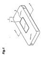
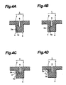
- Figs. 1 to 3 and 4A are respectively a perspective view showing the front side of the integrally molded air-bag cover article in accordance with one embodiment of the present invention, a perspective view showing the rear side thereof, a cross-sectional view taken along line A-A of the article shown in Fig. 1, and a partial cross-sectional view showing the article shown in Fig. 1 near its weak section.
- the integrally molded air-bag cover article 1 comprises an air-bag cover section (air-bag cover; 2) and a frame section 3, while the periphery 2a of the air-bag cover section 2 and the inner edge 3a of the frame section 3 are integrally and continuously formed with each other by way of a weak section 4.
- the integrally molded air-bag cover article 1 is a vehicle interior equipment such as instrument panel or door trim, and the air-bag cover section 2 is integrally molded with a part thereof.
- the air-bag cover 2 is disposed so as to correspond to the position of the air-bag device (not depicted) attached to the rear side of the instrument panel, door trim, or the like, while the size thereof is appropriately set such that it is not too large or too small when the air bag (not depicted) is inflated.
- a continuous protrusion 5 and a continuous groove-like recess are respectively formed in the undesigned surface (rear surface) and designed surface (front surface) so as to correspond to the periphery 2a of the air-bag cover section 2 .
- the weak section 4 in the integrally molded air-bag cover article 1 is constituted by a resin junction in which interfaces of a resin constituting the air-bag cover section 2 and a resin constituting the section (frame section; 3) other than the air-bag cover section 2 are connected together by the bonding action between these resins.
- the weak section (resin junction; 4) is formed so as to extend from the inner face of the groove 6 to the outer face of the protrusion 5 . Namely, the air-bag cover section 2 and the frame section 3 are joined together so as to form a resin interface at and around the protrusion 5, while the resin interface at the junction 4 of both resins is exposed to the groove-like recess 6. Consequently, the fracture strength at this resin junction 4 is lower than that in the other portions (air-bag cover section 2 and frame section 3 ).
- the cross-sectional form of the groove-like recess 6 is U-shaped or quadrangular in many cases and may be V-shaped in some cases.
- its width is not necessarily the same between its upper and lower ends, and the width of the upper end may be somewhat greater than that of the lower end.
- the width of the groove-like recess 6 should not preferably be too large from the viewpoint of appearances of the product, since the opening portion of the groove-like recess 6 is on the designed surface side.
- the width of the groove-like recess 6 at the upper end thereof is preferably not greater than 5 mm and more preferably not greater than 3 mm. It also holds true in the case where a skin material is attached to the surface of the article. Without being restricted in particular, it is sufficient for the lower limit of the width of the groove-like recess 6 to be such that the groove-like recess 6, can be recognized as a groove.
- the width of the groove-like recess 6 is preferably at least 0.3 mm.
- the depth of the groove-like recess 6 is arbitrary and not restricted in particular. In general, however, it is preferably within the range of 1/2 to five times as much as the thickness of the base material (portion other than the groove and protrusion).
- the size of the protrusion 5 depends on the depth and width of the groove-like recess 6 and is not restricted in particular, the lower limit of its width is normally not smaller than the sum of the thickness of base material portion and the width of groove-like recess and particularly preferably not smaller than the sum of 2 ⁇ (thickness of base material portion) + (width of groove-like recess).
- the upper limit of the width of the protrusion 5 is preferably not greater than the sum of 5 ⁇ (thickness of base material portion) + (width of groove-like recess).
- the height of the protrusion 5 depends on the depth of the groove-like recess 6, and the position where the resin junction (4 is disposed, in general, it preferably has such a height that the distance between the tip portion of the protrusion 5 and the bottom portion of the groove-like recess 6 is within the range of 1/2 to four times as much as the thickness of the base material.
- a molten resin is injected and supplied from a resin gate in a state where the molds are closed with a predetermined cavity clearance or in a state where, though the molds are open, the cavity clearance therebetween is very narrow.
- the molten resin is supplied between the molds from a plurality of resin gates.
- the molten resin When the molten resin is supplied between the molds from a plurality of resin gates, flows of molten resin from the respective resin gates merge together within the cavity.
- the difference in pressure between both resins within the cavity is changed so as to prevent the resin interface from being formed at the portion where both resins come into contact with each other, or the resin temperature is raised so as to prevent the viscosity of both resins in the cavity from lowering, whereby the molding condition is selected such that both resins fuse with each other and one resin enters the inside of the other resin, making the resin interface unclear or nonexistent.
- the resin constituting the air-bag cover section 2 and the resin constituting the other section 3 are formed such that the resin interface 4 of both resins is formed at the peripheral portion of the air-bag cover section 2 , the air-bag cover section 2 and the other section 3 are directly joined together upon the bonding action between the resins, and one end of the resin interface 4 is exposed to the inner face of the groove-like recess 6 so as to longitudinally extend from the inner face of the groove-like recess 6 to the outer face of the protrusion 5 .
- the bonding strength of both resins is appropriately and uniformly reduced at the resin interface 4 so as to have such a degree of fracture strength that its form can be maintained at the time of normal usage but, at the time when the air bag unfolds and inflates upon an impact, the resin interface 4 is broken due to the resulting pressure, whereby the air-bag cover section 2 is cut off from the frame section 3 .
- the resin interface 4 exposing its one end is thus directly joined to the inner face of the groove-like recess 6 so as to longitudinally extend from the inner face of the groove-like recess 6 to the outer face of the protrusion 5.
- both resins are joined together such that the resin interface therebetween is unclear or inexistent so as not to form a resin interface in the thickness portion of the base material as in the case of the above-mentioned conventional resin article, the strength at the joint becomes so strong that air-bag cover is not broken in response to an impact, whereby the air bag accommodated therein cannot be unfolded and, thus, the objects of the present invention cannot be attained.
- the resin interface 4 is formed so as to appear at the inner face of the groove-like recess 6 , the boundary portion of the resin interface cannot be seen from the designed surface side of the article 1 , thereby preventing the appearance of the interior equipment from deteriorating, and the air-bag cover section 2 is apparently broken along the groove-like recess 6 upon an impact.
- the resin interface 4 may be broken at the time of normal usage upon a slight external force when the fracture strength thereof is too low, whereas it may be hard to break upon an impact when its fracture strength is too high. Accordingly, a well-balanced desired level of strength is necessary. Such strength can be adjusted by the resin interface area and joining condition.
- the joining area becomes broader, thereby yielding a higher fracture strength.
- the area of the resin interface 4 decreases, the joining area becomes smaller, thereby yielding a lover fracture strength.
- the cross-sectional length of the resin interface 4 may be made greater.
- it may be formed with a smaller cross-sectional length.
- the joining condition is such that the resin forming the air-bag section 2 and the resin forming the other section 3 are prevented from merging together in their completely molten states.
- employed is a method in which the molten resin for forming the air-bag cover section 2 is initially supplied and cooled till it is solidified or almost solidified (to a state where a solidified layer is formed on at least the surface thereof) so as to lower its fluidity, and then the molten resin for forming the other section 3 is supplied thereto.
- the inner edge 3a of the frame section 3 project to the rear side of the periphery 2a of the air-bag cover section 2.
- the periphery (2a; front side) of the air-bag cover section 2 and the inner edge (3a; rear side) of the frame section 3 are configured so as to partially overlap each other in this manner, the periphery 2a of the air-bag cover section 2 is supported by the inner edge 3a of the frame section 3 from the rear side thereof.
- the pressure applied to the air-bag cover section 2 from the front side is dispersed into and absorbed by the inner edge 3a of the frame section 3 overlapping the periphery 2a, whereas the pressure applied to the air-bag cover section 2 from the rear side is converged on the resin junction 4.
- the strength required for a part of the vehicle interior equipment such as instrument panel is kept at the time of normal usage where a pressure greater than the fracture strength of the resin junction 4 is not applied thereto, whereby the integral form shown in Figs. 1 to 3 is maintained.
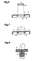
- the air bag (not depicted) disposed on the rear side of the air-bag cover section 2 inflates, an inflation pressure greater than the fracture strength of the resin junction 4 is applied to the air-bag cover section 2 from its rear side, whereby the resin junction 4 constituted by the periphery 2a, of the air-bag cover section 2 and the inner edge 3a of the frame section 3 is broken as shown in Figs. 5 and 6, whereby the air-bag cover section 2 is securely and instantly cut off from the frame section 3.
- the air-bag cover section 2 and the other section (frame section 3) of the integrally molded air-bag cover article 1 may be formed either by thermoplastic resins different from each other or by the same resin.
- thermoplastic resins include typical thermoplastic resins used for extrusion, injection molding, press molding, and the like, such as polyethylene, polypropylene, polystyrene, acrylonitrile-styrene-butadiene copolymer, polyvinyl chloride, polyamide, polycarbonate, polyethylene terephthalate, polybutylene terephthalate, polyphenylene ether, styrene-acrylonitrile copolymer, and acrylic resin; their mixtures; their polymer alloys; and their modified products. They are collectively referred to as thermoplastic resin in the present invention. Though such thermoplastic resins can be used in the integrally molded air-bag cover article 1 in accordance with the present invention without any limitation in particular, polypropylene resins are preferably used from the viewpoint of cost, performance, and the like.
- thermoplastic resins may be used alone; together with inorganic fillers such as talc, glass fiber, and calcium carbonate contained therein; or together with various compounding agents such as normally used stabilizer and pigment contained therein.
- a skin material 8 may be attached to the surface of the integrally molded air-bag cover article 1 in accordance with the present invention including the air-bag cover section 2 as shown in Figs. 7 and 8. Such a skin material 8 can further improve the appearance as an interior equipment.
- a portion of the skin material 8 is bent into the groove-like recess 6, while at least a part of the portion of the skin material 8 bent into the groove-like recess 6 preferably has an incision 8a. Since the incision 8a is provided, the skin material 8 is securely broken when the air-bag cover section 2 is cut off from the frame section 3. Also, since the incision 8a of the skin material 8 is formed within the groove-like recess 6, the appearance of the front surface (designed surface) of the skin material 8 is prevented from deteriorating.
- Examples of the skin material 8 used for this purpose include woven cloth, knitted cloth, nonwoven cloth, and the like, as well as sheets and films of various thermoplastic resins and thermoplastic elastomers. Also, thermoplastic resin foams of polyolefin, polyvinyl chloride, polystyrene, and the like; thermosetting resin foams of polyurethane and the like; or rubber foams of 4-polybutadiene, ethylenepropylene copolymer, and the like can be used.
- Such skin materials 8 may be used either independently or as a laminate in which at least two kinds of skin materials are combined together, such as a two-sheet laminate comprising a sheet made of polyvinyl chloride or thermoplastic elastomer and a polyolefin resin foam attached thereto, and a three-sheet laminate further comprising a backing thermoplastic sheet for protecting the foam. Also, the surface of such a skin material 6 may appropriately be provided with an irregular pattern such as emboss or subjected to decorating processing.
- the form of the resin junction (resin interface; 4) longitudinally extending from the inner face of the groove (6) to the outer face of the protrusion 5 is not restricted to that shown in Fig. 4A composed of a surface extending from the side face of the groove 6 on the side of the air-back cover section 2 so as to be perpendicular to the longitudinal direction (height direction) of the protrusion 5 and a surface extending from the bottom face of the protrusion 5 in parallel with the longitudinal direction thereof.
- the resin junction 4 may be formed by a surface extending from the bottom face of the groove (6) so as to be perpendicular to the longitudinal direction of the protrusion 5 and a surface extending from the bottom face of the protrusion 5 in parallel with the longitudinal direction as shown in Fig. 4B; by a surface extending from the side face of the groove 6 on the side of air-bag cover section 2 so as to be perpendicular to the longitudinal direction of the protrusion 5 as shown in Fig.
- the resin junction 4 is configured such that the inner edge 3a of the frame section 3 projects to the rear side of the periphery 2a of the air-bag cover section 2 , whereby a part of the periphery 2a on the front side overlaps with a part of the inner edge 3a on the rear side.
- integrally molded air-bag cover article 1) in accordance with the present invention having such a resin interface at the resin junction 4' between the air-bag cover section 2 and the other section (frame section; 3) can be manufactured by such methods as injection molding, injection compression molding, and stamping molding, explained in the following is a manufacturing example using injection compression molding method, which typically represents these methods.
- the mold assembly shown in Fig. 9 is constituted by a first mold 10a and a second mold 10b, each of which is attached to a press unit 11.
- the first mold (10a; fixed mold) is secured to a fixed frame 11a of the press unit 11.
- the second mold (10b; movable mold) is secured to a movable frame 11c which is connected to the fixed frame 11a through a connecting rod 11b .
- a driving unit 11d for the second mold 10b is connected to the movable frame 11c, so that the second mold 10b is movable in directions C (indicated by double-ended arrow C) in Pig. 9.
- the driving unit 11d for the second mold 10b may be a hydraulic driving unit, for example.
- the first and second molds 10a, 10b respectively have cavity faces 12a, 12b opposing each other and corresponding to the shape of a desired product. When the first and second molds 10a, 10b are closed, the cavity faces 12a, 12b define a cavity space coinciding with the outer shape of the desired product.
- the second mold 10b can be moved, by the press unit 11, among (i) a first open position where a cavity clearance (D in Fig. 9) between the cavity faces 12a, 12b of the first and second molds is maintained in a state (first open state) wherein the product can be taken out from between the first and second molds 10a, 10b ; (ii) a second open position where the cavity clearance is maintained in a state (second open state) to be smaller than that in the first open state (iii) a closed position where the cavity clearance is maintained in a state (closed state) to substantially match the thickness of the desired product.
- the first and second molds 10a, 10b can be maintained at a predetermined closing pressure by the press unit 11.
- the first and second molds 10a, 10b shown in Fig. 9 are in the first open state.
- the first mold 10a shown in Fig. 9 is a so-called male mold whose cavity face 12a is formed as a projecting portion
- the second mold 10b is a so-called female mold whose cavity face 12b is formed as a recessed portion.
- the first and second molds may respectively be female and male molds.
- the first and second molds may respectively be the movable and fixed molds, or both of the molds may be movable molds. Further, the first and second molds may respectively be upper and lower molds.
- the cavity space defined by the first and second cavity faces 12a, 12b comprises a first portion 13a for molding the air-bag cover section 2 and a second portion 13b for molding the other section (frame section; 3).
- a continuous groove section 14 having a shape corresponding to the protrusion 5 is formed at the boundary portion (position corresponding to the periphery 2a of the air-bag cover section 2 ) between the first and second portions 13a, 13b in the first cavity face 12a, whereas a continuous protruded section 15 having a form corresponding to the groove 6 is formed at the above-mentioned boundary portion in the second cavity face 12b .
- the cavity face 12a of the first mold 10a has at least one each of first and second resin gates 16a, 16b for supplying molten resins to first and second portions 13a, 13b , respectively.
- First and second gate opening/closing means 17a, 17b are respectively disposed around the first and second resin gates 16a, 16b so as to independently control the opening and closing actions of the latter.
- the gate opening/closing means may be either mechanical means (e.g., shut-off pin) or means (e.g., shut-off heater) for melting or solidifying the resin near the corresponding gate.
- the number of the first and second resin gates 16a, 16b is appropriately determined according to the size of the first and second portions, the shape of the desired product, or the like.
- a resin extruding unit 19 is connected to the first and second resin gates 16a, 16b by way of a resin passage 18 formed in the first mold 10a.
- the first mold 10a in the mold assembly shown in Fig. 9 has a slit 20 communicating with the groove section 14 and receiving therein a movable member 21 which temporarily parts the first and second portions 13a, 13b from each other.
- the movable member 21 is connected to a driving unit 22 and can move (slide) in directions E (directions substantially in parallel with the mold opening and closing directions C) shown in Fig. 9. Accordingly, the movable member 21 can be moved between a first position where it is completely received within the first mold 10a and a second position where the upper portion thereof projects from the cavity face 12a and abuts to the outer face of the protruded section 15.
- the driving unit 22 may be, for example, a driving unit utilizing pneumatic or hydraulic pressure, or an electromagnetic driving unit.
- a control unit (CPU; 23) is connected to the first and second gate opening/closing means 17a, 17b, the driving unit 22 for movable member, and the driving unit for press unit in order to control them. Their operations, the closing pressure of the first and second molds 10a, 10b, and the like are controlled by the control unit 23. Periods during which the first and second resin gates 16a, 16b are respectively opened, a period extending from closing of the first resin gate 16a to opening of the second resin gate 16b, a period extending from closing of the second resin gate 16b to actuating of the driving unit 11d for press unit, and the like are controlled by a timer 24 within the control unit 23.
- the first and second molds 10a, 10b are shifted from the first open state to the second open state, and then (T 3 to T 4 ) the movable member 21 is caused to project (slide to the second position) from the inner face of the groove section 14 of the first mold 10b so as to abut to the outer face of the protruded section 15 of the cavity face 12b of the second mold 10b.
- Fig. 11 shows a partial cross-sectional view of the state where the movable member 21 abuts to the outer face of the protruded section 15.
- the movable member 21 is temporarily parting the first portion 13a to be supplied with the resin for constituting the air-bag cover section 2 and the second portion 13b to be supplied with the resin for constituting the other section 3 from each other, and is provided in order to form the resin interface 4 at a portion where both resins merge together.
- the shape of the movable member 21 can arbitrarily be set according to the shape of the resin interface 4 to be formed thereby, it should be configured such that the tip portion and/or side wall portion of the movable member 21 can abut to the protruded section (15) at least at the initial resin-supplying time for the first portion 13a or second portion 13b, whereby the molten resin supplied to one portion is blocked by the movable member 21 from flowing into the other portion.
- the tip portion of the movable member 21 abuts to the protruded section (15) so as to mate with the tip portion of the latter, such that a surface thereof in one direction (on the second portion 13b side in Fig. 11) engages with the protruded section 15 more deeply.
- This configuration is effective in preventing the protruded section 15 from breaking due to the resin pressure when the first molten resin supplied to the first portion 13a flows within and fills the first portion 13a and in preventing the first molten resin from flowing into the second portion 13b from the gap between the movable member 21 and the protruded section 15.
- the position and cross-sectional form of the resin interface 4 can be adjusted by the form or arrangement of the movable member 21 .
- the interior equipment 1 having the resin interface 4 configured as shown in Fig. 4A can be obtained.
- the outer circumferential face of the movable member (21) at least on the first portion 13a side is made to slide on the inner wall of the groove section 14 , while the tip portion thereof is made horizontal and abut to the tip portion of the protruded section 15 .
- the movable member (21) may be configured so as to enclose therewith the portion of the protruded section 15 on the side of the second portion 13b bordered by the tip portion of the protruded section 15.
- the movable member 21 is moved (slid to the first position) so as to be received within the first mold 10a.
- an end face of the resin is formed at the periphery 2a of the air-bag cover section 2 having been in contact with the circumferential face of the movable member 21.
- the order of molding operations may be changed such that, before the molten resin is supplied to the first portion 13a so as to mold the air-bag cover section 2, the other section (frame section; 3) is initially molded.
- the skin material 8 is disposed beforehand between the cavity face 12a of the first mold 10a and the cavity face 12b of the second mold 10b as shown in Fig. 18, the interior equipment 1 shown in Fig. 7, in which the skin material 8 is integrally attached to the surface thereof while partially being bent into the groove 6 , can be manufactured.
- the incision 8a be formed in a part of or the whole portion of the skin material 8 that is bent into the groove 6 and in contact with the bottom of the latter, such that the skin material 8 is broken along the incision 8a simultaneously with the air-bag cover section 2 being cut off from the frame section 3 as the resin interface 4 is broken.
- the integrally molded air-bag cover article 1 which is formed such that the resin interface in the resin junction 4 between the resin constituting the air-bag cover section 2 and the resin constituting the other section 3 is formed so as to longitudinally extend from the inner face of the groove 6 formed in the front surface thereof to the outer face of the protrusion 5 formed in the rear surface thereof.
- the fracture strength of the air-bag cover upon unfolding of the air bag can be adjusted by the area or molding condition (joining condition) of the resin interface 4. More specifically, the area of the resin interface 4 can be adjusted by the shape of the movable member 21, the magnitude of the protrusion 5 , and the like.
- the fracture strength of the resin junction 4 can be adjusted.
- the integrally molded air-bag cover article in accordance with the present invention can securely and instantly be removed the air-bag cover upon inflation of the air bag at the time of a sudden impact, while normally maintaining the strength as a part of a vehicle interior equipment such as instrument panel, without necessitating any thin portion to be broken around the air-bag cover or discontinuously arranged through-holes to be broken formed by post-processing which may be problematic in terms of appearance. Also, since the integrally molded air-bag cover article in accordance with the present invention can easily be manufactured by a series of molding steps alone, which are similar to those for manufacturing a conventional vehicle interior equipment, its manufacturing and processing cost can be reduced.
- the fracture strength required for the air-bag cover can arbitrarily be adjusted without affecting the designed surface of the product at all. Accordingly, the integrally molded air-bag cover article, in which the fracture strength of the air-bag cover is correctly controlled in response to the inflation pressure of the air bag, can efficiently be obtained.
Landscapes
- Engineering & Computer Science (AREA)
- Mechanical Engineering (AREA)
- Manufacturing & Machinery (AREA)
- Air Bags (AREA)
- Instrument Panels (AREA)
- Moulds For Moulding Plastics Or The Like (AREA)
- Buffer Packaging (AREA)
Applications Claiming Priority (3)
| Application Number | Priority Date | Filing Date | Title |
|---|---|---|---|
| JP10927296A JP3326481B2 (ja) | 1996-04-30 | 1996-04-30 | エアーバッグカバー一体成形車両内装部品 |
| JP109272/96 | 1996-04-30 | ||
| JP10927296 | 1996-04-30 |
Publications (3)
| Publication Number | Publication Date |
|---|---|
| EP0805070A2 EP0805070A2 (en) | 1997-11-05 |
| EP0805070A3 EP0805070A3 (en) | 2000-07-19 |
| EP0805070B1 true EP0805070B1 (en) | 2002-09-11 |
Family
ID=14505973
Family Applications (1)
| Application Number | Title | Priority Date | Filing Date |
|---|---|---|---|
| EP97107088A Expired - Lifetime EP0805070B1 (en) | 1996-04-30 | 1997-04-29 | Integrally molded air-bag cover article and method of making the same |
Country Status (4)
| Country | Link |
|---|---|
| US (1) | US5947511A (ja) |
| EP (1) | EP0805070B1 (ja) |
| JP (1) | JP3326481B2 (ja) |
| DE (1) | DE69715292T2 (ja) |
Families Citing this family (34)
| Publication number | Priority date | Publication date | Assignee | Title |
|---|---|---|---|---|
| CA2256497C (en) * | 1997-03-26 | 2003-07-01 | Toyota Jidosha Kabushiki Kaisha | Interior member having an airbag door section for use in vehicles, and its molding method |
| US6835439B1 (en) | 1997-07-23 | 2004-12-28 | Toyota Shatai Kabushiki Kaisha | Panel for air bags and method of manufacturing the same |
| JP3434698B2 (ja) * | 1998-01-21 | 2003-08-11 | 日本プラスト株式会社 | エアバッグ収納用ケース |
| US6082762A (en) * | 1998-05-22 | 2000-07-04 | Larry J. Winget | Air bag cover having a decorative applique preform bonded thereto and method of making same |
| US6322100B1 (en) * | 1998-10-26 | 2001-11-27 | Trw Inc. | Deployment structure for an inflatable vehicle occupant protection device |
| AT406759B (de) * | 1999-04-08 | 2000-08-25 | Magna Eybl Gmbh | Abdeckung für ein airbag-modul |
| US6872345B1 (en) * | 1999-08-16 | 2005-03-29 | Decoma International Inc. | Method for forming a fascia assembly for a motor vehicle |
| AR026646A1 (es) * | 1999-12-08 | 2003-02-19 | Plabber Holding S A | Grupo auxiliar de inyeccion para moldes, para la conformacion de articulos de material plastico con al menos dos componentes |
| EP1274556A1 (en) * | 2000-04-20 | 2003-01-15 | Decoma Exterior Trim Inc. | Method and mold for molding a panel |
| DE20011466U1 (de) * | 2000-06-30 | 2000-11-16 | Trw Automotive Safety Sys Gmbh | Gassackmodulabdeckung und Gassackmodul |
| JP4788026B2 (ja) * | 2000-07-31 | 2011-10-05 | 旭硝子株式会社 | 車両用樹脂窓および車両用ドアパネル |
| US20020079677A1 (en) * | 2000-12-21 | 2002-06-27 | Skirha Martin Dirk | Instrument panel with integral hidden door cover and method of in-process manufacture thereof |
| US6568707B2 (en) | 2001-02-23 | 2003-05-27 | Lear Corporation | Molded seamless vehicle interior panel for concealing an airbag |
| US6756004B2 (en) * | 2002-04-24 | 2004-06-29 | Lear Corporation | Method for manufacturing cockpit-type instrument panels |
| CA2488254A1 (en) * | 2002-06-07 | 2003-12-18 | Intier Automotive Inc. | Multi-shot injection molded component and method of manufacture |
| US7108822B2 (en) * | 2002-07-29 | 2006-09-19 | Lear Corporation | Method of forming a vehicle trim panel |
| ES2255776B1 (es) * | 2003-01-15 | 2007-06-16 | M. Teresa Pla Estrada | Procedimiento de rotura facil en material termoplastico. |
| CN100513123C (zh) * | 2003-08-25 | 2009-07-15 | 约翰逊控制技术公司 | 装饰板的多部件注射模制 |
| US20050098996A1 (en) * | 2003-11-06 | 2005-05-12 | Enders Mark L. | Knee bolster cover |
| JP4492129B2 (ja) * | 2004-01-16 | 2010-06-30 | タカタ株式会社 | エアバッグ装置及びエンブレム付きモジュールカバー |
| US7232001B2 (en) | 2004-08-24 | 2007-06-19 | Sam Hakki | Collision air bag and flotation system |
| US7434829B2 (en) * | 2005-04-22 | 2008-10-14 | Visteon Global Technologies, Inc. | Interior panel having airbag deployment door |
| US20070264474A1 (en) * | 2006-05-11 | 2007-11-15 | Visteon Global Technologies, Inc. | Component for a vehicle interior and a mold assembly and a method for assembling the component |
| US20070278770A1 (en) * | 2006-06-02 | 2007-12-06 | Ken Love | Insert molded feature for airbag covers |
| FR2907400B1 (fr) * | 2006-10-19 | 2009-07-10 | Faurecia Interieur Ind Snc | Procede de fabrication d'un habillage interieur de masquage d'un coussin gonflage de securite pour vehicule automobile, et habillage interieur et vehicule automobile correspondant |
| DE102008005669A1 (de) * | 2008-01-21 | 2009-07-30 | Faurecia Innenraum Systeme Gmbh | Verkleidungsteil für ein Kraftfahrzeug |
| CZ306861B6 (cs) * | 2009-03-24 | 2017-08-16 | Megatech Industries Intellectual Property, S.L. | Odlévací forma s hradítkovým zařízením použitelná pro výrobu bimateriálových plastových dílců a se zlepšenou pohyblivostí |
| ES2375989B1 (es) * | 2009-03-24 | 2013-02-05 | Eurostyle Automotive Amurrio, S.A. | Dispositivo de esclusa, aplicable para la fabricación de piezas plásticas bimateria, con capacidad de movimiento mejorado. |
| US8459713B2 (en) | 2010-08-09 | 2013-06-11 | Autoliv Asp, Inc. | Assembly for attaching an emblem onto an airbag storage compartment cover |
| US9062386B2 (en) | 2011-03-01 | 2015-06-23 | Srg Global, Inc. | Methods of multi-shot injection molding and metal-plated polymeric articles made therefrom |
| US20160242476A1 (en) * | 2014-02-20 | 2016-08-25 | Robert Nutter | Hip protective disposable undergarment |
| JP6425908B2 (ja) * | 2014-03-25 | 2018-11-21 | 本田技研工業株式会社 | 射出成形方法、射出成形金型および成形品 |
| CN105628707B (zh) * | 2015-12-30 | 2018-05-08 | 中电环保股份有限公司 | 水处理树脂界面图像识别方法 |
| CN109789784B (zh) * | 2016-09-30 | 2022-04-12 | 本田技研工业株式会社 | 树脂部件及其成形方法、成形装置 |
Family Cites Families (7)
| Publication number | Priority date | Publication date | Assignee | Title |
|---|---|---|---|---|
| US5395668A (en) * | 1990-08-29 | 1995-03-07 | Toyoda Gosei Co., Ltd. | Air bag apparatus |
| JPH04185551A (ja) * | 1990-11-19 | 1992-07-02 | Toyota Motor Corp | 自動車用エアバツグカバー |
| JP2658604B2 (ja) * | 1991-03-12 | 1997-09-30 | トヨタ自動車株式会社 | エアバッグ装置 |
| JP2945559B2 (ja) * | 1993-03-31 | 1999-09-06 | 株式会社イノアックコーポレーション | エアバッグカバー部を有する車両内装部品の製造方法 |
| US5458361A (en) * | 1993-08-25 | 1995-10-17 | Davidson Textron Inc. | Insert for air bag cover assembly |
| JPH07309189A (ja) * | 1994-05-17 | 1995-11-28 | Inoac Corp | 車室側部材一体エアバッグドアの製造方法 |
| US5536037A (en) * | 1994-11-18 | 1996-07-16 | Trw Vehicle Safety Systems Inc. | Deployment door for use in a vehicle occupant restraint apparatus |
-
1996
- 1996-04-30 JP JP10927296A patent/JP3326481B2/ja not_active Expired - Lifetime
-
1997
- 1997-04-29 DE DE69715292T patent/DE69715292T2/de not_active Expired - Fee Related
- 1997-04-29 EP EP97107088A patent/EP0805070B1/en not_active Expired - Lifetime
- 1997-04-30 US US08/841,673 patent/US5947511A/en not_active Expired - Fee Related
Also Published As
| Publication number | Publication date |
|---|---|
| JPH09290666A (ja) | 1997-11-11 |
| DE69715292D1 (de) | 2002-10-17 |
| DE69715292T2 (de) | 2003-04-30 |
| JP3326481B2 (ja) | 2002-09-24 |
| EP0805070A2 (en) | 1997-11-05 |
| EP0805070A3 (en) | 2000-07-19 |
| US5947511A (en) | 1999-09-07 |
Similar Documents
| Publication | Publication Date | Title |
|---|---|---|
| EP0805070B1 (en) | Integrally molded air-bag cover article and method of making the same | |
| JPH03254919A (ja) | エアバッグのモジュールカバーの製造方法 | |
| US6042140A (en) | Air bag cover having a visually perceptible tear seam | |
| GB2249749A (en) | Moulding a module cover for an air bag device which has undercut portions in mounting edge portions thereof | |
| GB2419331A (en) | Automotive trim assembly and integral airbag door | |
| US5762362A (en) | Automotive air bag cover and method of molding same | |
| EP3730354B1 (en) | Airbag system for a vehicle and method for manufacturing the airbag system | |
| GB2419320A (en) | Moulding an automotive trim assembly with an integrated airbag door | |
| US20100164136A1 (en) | Method of manufacturing airbag lid section for vehicle | |
| EP0734915B1 (en) | Manufacturing method of pad | |
| US5750062A (en) | Method of manufacturing an air bag cover | |
| JP3428402B2 (ja) | エアバッグドア部を有する車両用内装部材及びその成形方法 | |
| JPH0452117A (ja) | エアバッグ装置のモジュールカバーの成形方法 | |
| JP3922122B2 (ja) | 自動車内装品本体 | |
| JP2005153232A (ja) | 射出成形品の製造方法 | |
| JP3879611B2 (ja) | 自動車内装品本体の製造方法 | |
| US10369953B2 (en) | Interior panels including substrates with inserts for defining integrated airbag deployment doors for motor vehicles and methods of making the same | |
| JP2002234413A (ja) | エアバッグ用カバー体成形方法 | |
| JP3899903B2 (ja) | 自動車内装品本体の製造方法 | |
| JP3879609B2 (ja) | 自動車内装品本体の製造方法 | |
| JP2006205837A (ja) | エアバッグドア部付車両用内装品及びその製造方法 | |
| JP2023144185A (ja) | エアーバッグリッドの製造方法 | |
| JPH0664495A (ja) | エアバッグのカバー体 | |
| KR20230081942A (ko) | 취출성 개선구조가 형성된 사출금형 | |
| JP5049499B2 (ja) | スラッシュ成形表皮材の製造方法及びスラッシュ成形型 |
Legal Events
| Date | Code | Title | Description |
|---|---|---|---|
| PUAI | Public reference made under article 153(3) epc to a published international application that has entered the european phase |
Free format text: ORIGINAL CODE: 0009012 |
|
| AK | Designated contracting states |
Kind code of ref document: A2 Designated state(s): DE FR GB IT |
|
| PUAL | Search report despatched |
Free format text: ORIGINAL CODE: 0009013 |
|
| AK | Designated contracting states |
Kind code of ref document: A3 Designated state(s): DE FR GB IT |
|
| 17P | Request for examination filed |
Effective date: 20001006 |
|
| 17Q | First examination report despatched |
Effective date: 20010314 |
|
| GRAG | Despatch of communication of intention to grant |
Free format text: ORIGINAL CODE: EPIDOS AGRA |
|
| GRAG | Despatch of communication of intention to grant |
Free format text: ORIGINAL CODE: EPIDOS AGRA |
|
| GRAH | Despatch of communication of intention to grant a patent |
Free format text: ORIGINAL CODE: EPIDOS IGRA |
|
| GRAH | Despatch of communication of intention to grant a patent |
Free format text: ORIGINAL CODE: EPIDOS IGRA |
|
| GRAA | (expected) grant |
Free format text: ORIGINAL CODE: 0009210 |
|
| AK | Designated contracting states |
Kind code of ref document: B1 Designated state(s): DE FR GB IT |
|
| REG | Reference to a national code |
Ref country code: GB Ref legal event code: FG4D |
|
| REF | Corresponds to: |
Ref document number: 69715292 Country of ref document: DE Date of ref document: 20021017 |
|
| ET | Fr: translation filed | ||
| PLBE | No opposition filed within time limit |
Free format text: ORIGINAL CODE: 0009261 |
|
| STAA | Information on the status of an ep patent application or granted ep patent |
Free format text: STATUS: NO OPPOSITION FILED WITHIN TIME LIMIT |
|
| 26N | No opposition filed |
Effective date: 20030612 |
|
| PGFP | Annual fee paid to national office [announced via postgrant information from national office to epo] |
Ref country code: FR Payment date: 20040408 Year of fee payment: 8 |
|
| PGFP | Annual fee paid to national office [announced via postgrant information from national office to epo] |
Ref country code: GB Payment date: 20040428 Year of fee payment: 8 |
|
| PGFP | Annual fee paid to national office [announced via postgrant information from national office to epo] |
Ref country code: DE Payment date: 20040506 Year of fee payment: 8 |
|
| PG25 | Lapsed in a contracting state [announced via postgrant information from national office to epo] |
Ref country code: IT Free format text: LAPSE BECAUSE OF NON-PAYMENT OF DUE FEES Effective date: 20050429 Ref country code: GB Free format text: LAPSE BECAUSE OF NON-PAYMENT OF DUE FEES Effective date: 20050429 |
|
| PG25 | Lapsed in a contracting state [announced via postgrant information from national office to epo] |
Ref country code: DE Free format text: LAPSE BECAUSE OF NON-PAYMENT OF DUE FEES Effective date: 20051101 |
|
| GBPC | Gb: european patent ceased through non-payment of renewal fee |
Effective date: 20050429 |
|
| PG25 | Lapsed in a contracting state [announced via postgrant information from national office to epo] |
Ref country code: FR Free format text: LAPSE BECAUSE OF NON-PAYMENT OF DUE FEES Effective date: 20051230 |
|
| REG | Reference to a national code |
Ref country code: FR Ref legal event code: ST Effective date: 20051230 |