EP0805025B1 - Druckgutfördervorrichtung zwischen Druckwerken - Google Patents
Druckgutfördervorrichtung zwischen Druckwerken Download PDFInfo
- Publication number
- EP0805025B1 EP0805025B1 EP97107245A EP97107245A EP0805025B1 EP 0805025 B1 EP0805025 B1 EP 0805025B1 EP 97107245 A EP97107245 A EP 97107245A EP 97107245 A EP97107245 A EP 97107245A EP 0805025 B1 EP0805025 B1 EP 0805025B1
- Authority
- EP
- European Patent Office
- Prior art keywords
- printed products
- products according
- conveying printed
- printing
- conveying
- Prior art date
- Legal status (The legal status is an assumption and is not a legal conclusion. Google has not performed a legal analysis and makes no representation as to the accuracy of the status listed.)
- Expired - Lifetime
Links
- 238000007639 printing Methods 0.000 title claims description 116
- 239000002184 metal Substances 0.000 claims description 15
- 230000008878 coupling Effects 0.000 claims description 11
- 238000010168 coupling process Methods 0.000 claims description 11
- 238000005859 coupling reaction Methods 0.000 claims description 11
- 238000012545 processing Methods 0.000 claims description 5
- 230000007704 transition Effects 0.000 claims description 3
- 239000000463 material Substances 0.000 description 24
- 241000251730 Chondrichthyes Species 0.000 description 6
- 238000013461 design Methods 0.000 description 3
- 238000009434 installation Methods 0.000 description 3
- 238000010276 construction Methods 0.000 description 2
- 238000011161 development Methods 0.000 description 2
- 230000001681 protective effect Effects 0.000 description 2
- 230000000717 retained effect Effects 0.000 description 2
- 230000001174 ascending effect Effects 0.000 description 1
- 230000000712 assembly Effects 0.000 description 1
- 238000000429 assembly Methods 0.000 description 1
- 238000005352 clarification Methods 0.000 description 1
- 230000009189 diving Effects 0.000 description 1
- 238000012423 maintenance Methods 0.000 description 1
- 238000000034 method Methods 0.000 description 1
- 238000010422 painting Methods 0.000 description 1
- 238000004091 panning Methods 0.000 description 1
- 238000007493 shaping process Methods 0.000 description 1
Images


Classifications
-
- B—PERFORMING OPERATIONS; TRANSPORTING
- B65—CONVEYING; PACKING; STORING; HANDLING THIN OR FILAMENTARY MATERIAL
- B65H—HANDLING THIN OR FILAMENTARY MATERIAL, e.g. SHEETS, WEBS, CABLES
- B65H5/00—Feeding articles separated from piles; Feeding articles to machines
- B65H5/16—Feeding articles separated from piles; Feeding articles to machines by pusher, needles, friction, or like devices adapted to feed single articles along a surface or table
-
- B—PERFORMING OPERATIONS; TRANSPORTING
- B41—PRINTING; LINING MACHINES; TYPEWRITERS; STAMPS
- B41F—PRINTING MACHINES OR PRESSES
- B41F13/00—Common details of rotary presses or machines
-
- B—PERFORMING OPERATIONS; TRANSPORTING
- B41—PRINTING; LINING MACHINES; TYPEWRITERS; STAMPS
- B41F—PRINTING MACHINES OR PRESSES
- B41F21/00—Devices for conveying sheets through printing apparatus or machines
- B41F21/08—Combinations of endless conveyors and grippers
-
- B—PERFORMING OPERATIONS; TRANSPORTING
- B41—PRINTING; LINING MACHINES; TYPEWRITERS; STAMPS
- B41F—PRINTING MACHINES OR PRESSES
- B41F7/00—Rotary lithographic machines
- B41F7/16—Rotary lithographic machines for printing on non-deformable material, e.g. sheet metal
-
- B—PERFORMING OPERATIONS; TRANSPORTING
- B65—CONVEYING; PACKING; STORING; HANDLING THIN OR FILAMENTARY MATERIAL
- B65H—HANDLING THIN OR FILAMENTARY MATERIAL, e.g. SHEETS, WEBS, CABLES
- B65H2511/00—Dimensions; Position; Numbers; Identification; Occurrences
- B65H2511/20—Location in space
- B65H2511/21—Angle
- B65H2511/214—Inclination
Definitions
- the invention relates to a printing material conveying device for printing units of printing presses, the Printing material conveying device a first printing unit is subordinate for accessibility of the first Printing unit has a displaceable section, a display and a transport device owns and the print material a finishing location feeds, and being the transport device at least one endless conveyor with pusher links for the printed matter.
- a printing material conveying device of the type mentioned Art is known and is used for the printing unit the printing material leaving the printing press To supply processing location, in particular one another printing unit of a multicolour printing machine.
- the printing material conveying device has one of several, parallel to each other at a distance Belts of existing endless belt conveyors on which the print material from the printing unit housing promotes.
- At least one of the endless dreams of Transport device is as provided with thrust links Endless conveyor trained.
- a print item for example a sheet of metal, which is the (first) printing unit leaves, is thus connected in series by means of the two Endless belt conveyors, one form the so-called display, the horizontal one Run of the transport device, wherein the shark fin-like thrust links of the chain having endless conveyor the rear edge of the Reach behind the sheet and in this way and Feed the print material to the following printing unit.
- the shark fin-like thrust members of thrust rollers one Endless run of the transport device overhauled, which take over the rear edge of the metal sheet and the front edge of the board the contact marks of the printing cylinder of the subsequent printing unit at somewhat increased speed respectively.
- the under spring tension standing thrust rollers cause an exact position of the Front edge of the board at the landing marks and dive after creating the sheet, according to the Deflection area of the associated endless run, from.
- the one to the transport device leading endless belt conveyor known printing material conveying device is preferred formed in two parts, that is, it points a pivot axis between its two ends, such that - viewed from the operator's side - can assume a V-shaped position with the consequence that in the working position the printing unit Delivery end facing obliquely or vertically stands upwards, so that there is a release position results, that is, it becomes an "alley" in the Printed material conveying path formed, which is an accessibility to the printing unit.
- the said Accessible endless belt conveyors a constructional, certain overall length and on the other hand the subsequent transport device also a certain one, through which co-determining the largest possible format of the printed material Can not be less than the overall length, this leads to a relatively large distance between each Printing units of a multicolour printing machine.
- a four-color press which by means of an investor sheet of a stack and the one painting machine follows, there is an overall length of around 30 meters, that is, the well-known design needs correspondingly large installation rooms.
- EP 0 545 862 A1 discloses a printing material conveying device out having an endless conveyor Push elements for the conveyed goods.
- the Pushing elements act on the rear edge of the material to be conveyed and move it in the direction of transport.
- German publication 1 237 533 a device for conveying and aligning one above the other laid out brochures that a lower and has an upper conveyor belt. Further an endless chain is provided on the stops are attached, the rear edge of the to be transported Load goods.
- the invention has for its object a Printing material conveying device of the aforementioned To create a type that is shorter in design, which increases the overall length of a printing press reduced and therefore an installation room with smaller Sufficient space for installation is.
- this object is achieved by that the relocatable section is part of the Transport device is and that the endless conveyor down to the displaceable section extends. Because of this configuration according to the invention is the accessibility mentioned on the delivery side of the printing unit from a section of the Transport device taken, this section is displaceable so that it is in his release position the one already mentioned "Alley" creates in the transport route.
- the one with the preferred Shark fin-like thrust links Endless conveyor extends into the relocatable Section into it, that is, through the The largest format specified length is retained, however, a section of this length provides accessibility enables so that - compared to the known Design - the V-shaped endless belt conveyor can be omitted.
- the processing location is in particular another, second printing unit.
- the transport device has a fixed Section and the displaceable section and that the one provided with thrust links Continuous conveyor across both sections extends.
- the first pivot axis is around which the relocatable section is pivotally mounted. In the working position of the pivotable section results in a continuous Transport path for the printed matter; in the swiveled The release position is access to the associated one Printing unit granted.
- the first pivot axis runs transversely to Direction of conveyance of the printed material.
- the first The pivot axis is in particular horizontal aligned.
- the first pivot axis preferably runs perpendicular to the conveying direction of the Printed matter.
- the first printing unit is the relocatable section preferably from his working position the first swivel axis down to the release position swiveling.
- the displaceable section is pivoted preferably by means of a mechanical drive.
- the machine drive preferably has at least one piston / cylinder unit.
- the transport device one by one second pivot axis displaceable first work platform arranged on the work platform.
- This first Work platform thus forms a section of the Working platform assigned to the first printing unit is.
- a mechanical platform drive engages on the one hand on a stationary machine frame and on the other hand on the swiveling first work platform to pivot them. This panning is done by setting up the free end the work platform, that is, the free end is preferably pivoted approximately vertically upwards. It is envisaged that the first work platform via at least one coupling element with one Cover element is connected by means of a third pivot axis pivotable on the machine frame is stored.
- the mechanical platform drive has at least one further, second piston / cylinder unit on. It is also advantageous if the coupling element as at least one coupling rod is trained.
- the cover element can be preferred be designed as a cover plate. In working position of the pivotable section of the Transport device, i.e.
- this is preferably a cover plate trained cover element below the displaceable Section of the transport device, and in the area of the "still closed" alley.
- the displaceable section of the Transport device by means of the mechanical drive, preferably by means of the first piston / cylinder unit, pivoted downwards.
- the mechanical platform drive activated the swiveling, first work platform pivoted upwards, by means of the coupling element also preferably as a cover plate trained cover element is taken, that is, the cover plate gives the due to the swung away, relocatable section of the Transport device already formed "alley" also free.
- the displaceable section of the transport device are assigned to the first pivot axis having.
- This construction means that free end of the displaceable section of the transport device down from the first printing unit is folded away that the free end of the first work platform the working platform from the printing unit is folded away upwards, and that the during printing toward the first Printing unit-facing free end of the cover element upwards, away from the printing unit, into the protective position is shifted, so in its approximately vertical Protection position the folded, relocatable section shields the transport device.
- the working platform has a second platform that is above the fixed section of the transport device located.
- the second platform also pivoted be, with the associated pivot axis on the second printing unit facing away from the second Platform lies so that the free end of the second Platform swinging up from that second printing unit up along one Arc removed and thus access to the below located section of the transport device and also to the second printing unit on its system page granted.
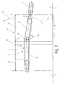
- Figure 1 shows a first printing unit 1 and a second printing unit 2 a not shown Printing machine, preferably as a sheet metal printing machine is formed, that is, the one to be printed Printed matter is sheet metal.
- the printing press can - via the two named Printing units 1 and 2 - further printing units have, but are not shown and for understanding the invention additionally contribute nothing.
- a printed material conveying device 3 which consist of a display 4 and a transport device 5.
- the display 4 is inside the housing 6 of the first Printing unit 1. Those leaving the first printing unit 1 Metal sheets become from the delivery 4 to the transport device 5 transported, which takes over and the second printing unit 2 on the inlet side feeds.
- the transport device 5 has one fixed, preferably horizontal Section 7 and a relocatable section 8 on, in the direction of pressure (arrow 9), that is from Printing unit 1 to printing unit 2 seen - the printing unit 1 facing free end of the displaceable section 8 of the transport device 5 to the display 4 connects and being the displaceable section 8 in the course of its transport movement Metal sheets along an ascending, flat movement path moved to a higher level on which the fixed section 7 of the transport device 5 is located. Reach the metal sheets this higher level, so they are determined by the fixed so not pivotable section 7 of the Transport device 5 in the direction of the second Printing unit 2 moves and finally on the inlet side the second printing unit 2 and finally hand over to the second printing unit 2 on the inlet side.
- Figure 1 is the - with a solid line displaceable section 8 of the transport device 5 shown in his working position, which during of the printing operation of the printing press is.
- the dash-dotted line indicates in FIG. 1 that that the displaceable section 8 by one first pivot axis 10 into a release position - can be pivoted along the circular arc 11.
- the transport device 5 has several endless runs 13, the following - in particular in the Figures 4 and 5- will be described in more detail.
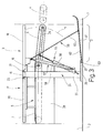
- a with Thrust members 14 provided endless conveyor 15 itself continuously over both sections of the transport device 5 extends, namely both over the horizontal extending section 7 as well as over the relocated section 8. This goes more clearly from Figure 2, in which the endless conveyor 15 shown with a broken line is.
- the two sections 7 and 8 have in their Transition area to the first pivot axis 10 which the displaceable section 8 from its counterpart to display 4 in a downward direction Position, especially in a vertical position downward position is relocatable.
- the endless conveyor 15 at "sags" when swiveled into the release position at least one support wheel 16 is provided, the - from below - the lower run of the endless conveyor 15 supports.
- Figure 2- the axis of rotation of the support wheel 16 below and in Direction to the printing unit 1 offset to the first Swivel axis 10.
- Figure 2 also indicates schematically that a work platform above the printed material conveying device 3 17 is located by the operating personnel via a suitable stairs, not shown, can be entered can and access to the two printing units 1 and 2 granted because the work platform 17 the entire distance bridged between the two printing units 1 and 2.
- the work platform 17 has a first work platform 18 assigned to the printing unit 1 is.
- a second pivot axis 21 which is approximately in the middle between the printing units 1 and 2 assigned fixed section 19 is, the first work platform 18 in Swivel in the direction of arrow 22.
- This Swivel movement can be vertical or vertical about vertical position, whereby that already apparent from Figure 1 Alley 12 is released, that is, also in the area the work platform 17 becomes full access to the Printing unit 1 granted.
- the second work platform 20 is also designed to be pivotable. For this it is assigned to a fixed section 19 Swivel axis 23 can be pivoted upwards, so that access from above to the fixed one Section 7 of the transport device 5 is released.
- the open position is preferred the second work platform 20 by means of a Gas spring not shown fixed.
- FIG. 3 illustrates a machine frame 24, that on both sides of the by the printed material conveyor 3 trained transport routes - one vertically extending carrier 25 which on its upper end of the fixed section 19 of the Working platform 17 carries.
- a foot 26 At the bottom of each Carrier 25 is a foot 26 which is arranged with its end region 27 in the direction of the printing unit 1 extends.
- On the respective carrier 25 is a Cross member 28 attached to which the horizontal Section 7 of the transport device 5 attached is.
- Axis of rotation 10 formed, that is, between the two opposite each other Cross members 28 is the displaceable section 8 of the Transport device 5 along the from the figures 1 and 2 visible circular arc 11 pivotable stored.
- FIG. 4 makes it clear that the individual endless belt conveyors or endless runs of Delivery 4 and transport device 5 are not wide, continuous bands or the like, but that there are always several narrow, parallel to each other, spaced bands are provided.
- the display exists in detail 4 out of six parallel to each other Band runs, each facing the printing unit 1 Deflection wheel 30 and one facing away from the printing unit 1 Have deflection wheel 31.
- the two idler wheels 30 and 31 are wrapped in belt loops 32, so that in this way an endless belt conveyor 33 is formed.
- the endless belt conveyor 33 is by means of a not shown Drive, preferably by means of the drive of the Printing unit 1 operated.
- the transport device 5 has - according to Figure 4- im Area of the displaceable section 8 a first Endless run 34 on that of seven parallel to each other extending, spaced from each other Single belt conveyors 35 is formed.
- Everyone Single belt conveyor 35 has a deflection wheel 36, that with a short distance to the respective deflection wheel 31 is opposite the display 4 on "gap”.
- Further deflection wheels 37 are provided, one each Deflection wheel 36 and a deflection wheel 37 from a belt loop 38 is entwined.
- the deflection wheels 37 are rotatable about the pivot axis 10 already mentioned stored.
- the fixed section 7 of the transport device 5 has an endless strand 39 which consists of four parallel to each other, spaced apart lying single belt conveyors 40.
- Everyone Single belt conveyor 40 has a deflection wheel 41, which is rotatable about the first axis of rotation 10 is.
- Deflection wheels 42 are also provided, wherein always a deflection wheel 41 and a deflection wheel 42 of one Band loop 43 are wrapped.
- each single belt conveyor 45 has a deflection wheel 46 which is around the first Pivot axis 10 is rotatably mounted. Furthermore are Deflection wheels 47 are provided, each around a deflection wheel 46 and a deflection wheel 47 a belt loop 48 is performed.
- the transport device 5 is an endless conveyor 49 assigned to the two parallel to each other, spaced chain strands 50.
- Each Chain center 50 has a displaceable section 8 located deflection wheel 51 and one deflection wheel located in the fixed section 7 52.
- each of the two chain strands 50 is over an approximately central deflection wheel 53 guided is rotatably mounted about the first pivot axis 10.
- the respective chain center is also supported 50 by means of a not shown in FIG. however in the description of FIG. 2 mentioned, support wheel 16 from below.
- FIGS. 4 and 5 show that the chain runs 50 of the endless conveyor 49 with those already mentioned Thrust members 14 is provided, the rear edge reach behind the sheet to be conveyed and in this way the metal sheets in a defined Advance position and thus towards move to printing unit 2.
- the endless run 44 overtakes the endless conveyor 49, that is, push rollers 54 of the endless strand 44 overtake the thrust links designed like shark fins 14 of the endless conveyor 49, whereby the trailing edge of the respective sheet of metal to the Push rollers 54 are passed so that the push members 14 dive safely into the deflection area can and do not damage the respective trailing edge of the board.
- Figures 4 and 5 show that the Rotation axis of the deflection wheels 51 to the rotation axis of the deflection wheels 36 offset in the direction of the printing unit 2 lies. It can also be seen that the Axis of rotation of the deflection wheels 42 a distance from Have printing unit 2. A smaller distance from Printing unit 2 have the axes of rotation of the deflection wheels 52 and the axes of rotation of the deflection wheels 47 are on next to the printing unit 2, such that the end of the Endless runs 44 directly opposite. Further it can be seen that the single belt conveyor 40 des Endless runs 39 - from the drive side respectively seen from the operator side of the printing press between the second and third respectively third and fourth single belt conveyors 35 of the first endless run 34. Between each first and second single belt conveyors 40 of the endless strand 39 are the single belt conveyors 45 of the endless strand 44 and the chain dreams 50 of the endless conveyor 49.
- a machine drive 55 is assigned, that of two, each pivotable on the carrier 25 on the one hand and on the other hand pivotable on the frame 29 attacking piston / cylinder units 56 is formed.
- a mechanical platform drive provided that also consists of two piston / cylinder units 58 exists.
- Each piston / cylinder unit 58 can be swiveled on the machine frame 24, namely attached to the carrier 25 and also swiveling with the first work platform 18 connected.
- coupling elements 59 provided, which are designed as coupling rods 60 are.
- Each coupling rod 60 has one end pivotable with the first work platform 18 and can be pivoted with the other end connected to a cover member 61.
- the cover element 61 is designed as a cover plate 62, the by means of a third pivot axis 63 at the end region 27 of the foot 26 is mounted. 3 shown, running horizontally, so closed Position of the first work platform 18, the cover plate 62 extends starting from it third pivot axis 63- slightly obliquely upwards towards the printing unit 1.
Landscapes
- Engineering & Computer Science (AREA)
- Mechanical Engineering (AREA)
- Delivering By Means Of Belts And Rollers (AREA)
- Framework For Endless Conveyors (AREA)
- Separation, Sorting, Adjustment, Or Bending Of Sheets To Be Conveyed (AREA)
- Feeding Of Articles By Means Other Than Belts Or Rollers (AREA)
Applications Claiming Priority (2)
| Application Number | Priority Date | Filing Date | Title |
|---|---|---|---|
| DE19617503A DE19617503A1 (de) | 1996-05-03 | 1996-05-03 | Druckgutfördervorrichtung für Druckwerke von Druckmaschinen |
| DE19617503 | 1996-05-03 |
Publications (3)
| Publication Number | Publication Date |
|---|---|
| EP0805025A2 EP0805025A2 (de) | 1997-11-05 |
| EP0805025A3 EP0805025A3 (de) | 1998-01-07 |
| EP0805025B1 true EP0805025B1 (de) | 2000-01-19 |
Family
ID=7793040
Family Applications (1)
| Application Number | Title | Priority Date | Filing Date |
|---|---|---|---|
| EP97107245A Expired - Lifetime EP0805025B1 (de) | 1996-05-03 | 1997-05-01 | Druckgutfördervorrichtung zwischen Druckwerken |
Country Status (5)
| Country | Link |
|---|---|
| US (1) | US5950540A (ja) |
| EP (1) | EP0805025B1 (ja) |
| JP (1) | JPH1059574A (ja) |
| DE (2) | DE19617503A1 (ja) |
| ES (1) | ES2143263T3 (ja) |
Families Citing this family (6)
| Publication number | Priority date | Publication date | Assignee | Title |
|---|---|---|---|---|
| JPH11207927A (ja) * | 1997-11-05 | 1999-08-03 | Heidelberger Druckmas Ag | 枚葉紙輪転印刷機のためのリニア駆動装置を有する反転装置 |
| CA2483679C (en) * | 2002-03-22 | 2010-11-30 | Magnum Manufacturing Limited | Method and apparatus for overlapping sheets in a sheet feeder and providing the overlapped sheets to a printing press |
| DE102005055364A1 (de) | 2005-11-17 | 2007-05-24 | Kba-Metronic Ag | Vorrichtung und Verfahren zum Fördern bogenförmiger Objekte |
| CN101016115B (zh) * | 2007-02-25 | 2010-05-19 | 常熟市诚达港务机械设备厂 | 升降式输送机 |
| CN110668219B (zh) * | 2019-09-30 | 2022-01-07 | 武汉工程大学 | 一种用于印刷上料装置 |
| EP3851279B1 (de) * | 2020-01-20 | 2023-08-09 | Heidelberger Druckmaschinen AG | Vorrichtung zum handhaben von druckplatten an einer druckmaschine |
Family Cites Families (14)
| Publication number | Priority date | Publication date | Assignee | Title |
|---|---|---|---|---|
| DE618260C (de) * | 1931-04-21 | 1935-09-07 | Albert Schnellpressen | Druckmaschine fuer Bogendruck mit mehreren hintereinanderliegenden, unter sich gleichen und gleichsinnig laufenden Druckwerken zum Herstellen von Mehrfarbendruck und Schoen- und Widerdruck in einem Arbeitsgange |
| DE703284C (de) * | 1939-04-09 | 1941-03-05 | Maschf Augsburg Nuernberg Ag | Zweitourenschnellpresse mit Frontbogenausgang |
| US3204557A (en) * | 1963-06-06 | 1965-09-07 | American Can Co | Dry offset printing method |
| DE1237533B (de) * | 1965-08-11 | 1967-03-30 | Leipziger Buchbindereimaschine | Vorrichtung zum Foerdern und Ausrichten uebereinandergelegter Broschueren |
| DE1267228B (de) * | 1966-05-05 | 1968-05-02 | Koenig & Bauer Schnellpressfab | Bogenfuehrungseinrichtung fuer eine Bogen-Offset-Rotationsdruckmaschine |
| GB1415693A (en) * | 1972-04-25 | 1975-11-26 | Metal Box Co Ltd | Sheet feeding apparatus and method |
| US4062532A (en) * | 1976-04-23 | 1977-12-13 | Koppers Company, Inc. | Apparatus for feeding and transporting paperboard blanks |
| US4176601A (en) * | 1977-06-27 | 1979-12-04 | Precision Screen Machines, Inc. | Automated towel transfer printing, feeding, drying and folding apparatus |
| US4669715A (en) * | 1984-12-08 | 1987-06-02 | Heidelberger Druckmaschinen Ag | Sheet turning device for small offset printing machines or printing units |
| FR2585287B1 (fr) * | 1985-07-26 | 1988-07-08 | Martin Sa | Machine pour le traitement de feuilles de carton defilant successivement notamment machine d'impression |
| US5289773A (en) * | 1991-03-14 | 1994-03-01 | Komori Corporation | Apparatus for mounting plate on plate cylinder |
| EP0526677A1 (fr) * | 1991-08-06 | 1993-02-10 | Corradi S.A. | Procédé et dispositif d'alimentation d'un poste de travail en produits plats à partir d'au moins une pile de tels produits |
| EP0545862B1 (en) * | 1991-12-03 | 1998-04-22 | Crown Cork & Seal Company, Inc. | Method and apparatus for printing multicolored container body blanks in a single pass |
| FR2705953B1 (fr) * | 1993-06-02 | 1995-08-04 | Bourg Sa Cp | Dispositif de transfert de liasses de feuilles d'une machine imprimante ou copieuse vers une machine de finition. |
-
1996
- 1996-05-03 DE DE19617503A patent/DE19617503A1/de not_active Withdrawn
-
1997
- 1997-05-01 ES ES97107245T patent/ES2143263T3/es not_active Expired - Lifetime
- 1997-05-01 EP EP97107245A patent/EP0805025B1/de not_active Expired - Lifetime
- 1997-05-01 DE DE59701026T patent/DE59701026D1/de not_active Expired - Fee Related
- 1997-05-05 US US08/851,418 patent/US5950540A/en not_active Expired - Fee Related
- 1997-05-06 JP JP9115667A patent/JPH1059574A/ja active Pending
Also Published As
| Publication number | Publication date |
|---|---|
| US5950540A (en) | 1999-09-14 |
| DE59701026D1 (de) | 2000-02-24 |
| EP0805025A3 (de) | 1998-01-07 |
| ES2143263T3 (es) | 2000-05-01 |
| JPH1059574A (ja) | 1998-03-03 |
| DE19617503A1 (de) | 1997-11-06 |
| EP0805025A2 (de) | 1997-11-05 |
Similar Documents
| Publication | Publication Date | Title |
|---|---|---|
| EP0623542B1 (de) | Einrichtung zur Bildung eines sich senkrecht zu den stehend aneinandergereihten Druckbogen erstreckenden Stapels | |
| DE3700959C2 (de) | Bogensammelvorrichtung | |
| CH660353A5 (de) | Verfahren und vorrichtung zum unterteilen eines schuppenstromes aus druckbogen in teilschuppen. | |
| EP0497002A1 (de) | Vorrichtung zum Bilden einer Lücke in einem Schuppenstrom | |
| DE69208592T2 (de) | Verfahren und Vorrichtung zum Öffnen eines selbstschliessenden Greifers eines Greiferförderers | |
| EP0510525B1 (de) | Verfahren und Einrichtung zum Verarbeiten von Druckereiprodukten | |
| DE2141271C3 (de) | Förderer für Druckerzeugnisse und ähnliches Fördergut | |
| DE2414954A1 (de) | Einrichtung zum herstellen von luecken zwischen den von einem foerderer getragenen papierboegen | |
| EP0144061A2 (de) | Vorrichtung zum fördern von geschnittenen Metallteilen | |
| EP0478911B1 (de) | Vorrichtung zum wahlweisen Überführen von Erzeugnissen aus einer entlang eines ersten Förderweges transportierten Schuppenformation auf einen zweiten Förderweg | |
| EP0773179B1 (de) | Einrichtung zur Hilfsstapelbildung beim Nonstopstapelwechsel im Ausleger einer Druckmaschine | |
| EP0805025B1 (de) | Druckgutfördervorrichtung zwischen Druckwerken | |
| DE3540203A1 (de) | Vorrichtung zum beseitigen von lufteinschluessen aus papierstapeln | |
| DE1951598C3 (de) | Auswelchspur für eine Arbeitsvorrichtung enthaltende Fertigungsstraßen | |
| DE1806888A1 (de) | Foerdervorrichtung zum Ausrichten von Gegenstaenden | |
| CH670809A5 (ja) | ||
| EP0638502B1 (de) | Transport-Einrichtung für Blattlagen | |
| EP1072546B1 (de) | Förderanlage zum Zusammentragen und Bearbeiten von Druckbogen | |
| DE69814605T2 (de) | Vorrichtung zur automatischen Entfernung von Abfällen in der Herstellung von Papierrollen | |
| DE3308069A1 (de) | Vorrichtung zum zusammenfuehren von teilbahnen ueber umlenkwalzen in eine gemeinsame ebene | |
| DE102020126743A1 (de) | Materialverarbeitungseinrichtung | |
| EP3851279A1 (de) | Vorrichtung zum handhaben von druckplatten an einer druckmaschine | |
| DE3840647C2 (de) | Vorrichtung zum Weiterfördern von Druckprodukten | |
| EP0019036B1 (de) | Vorrichtung zum Stapeln von quaderförmigen Produkten, insbesondere von quaderförmigen Druckerzeugnissen, Zeitschriften oder dergleichen | |
| DE4304841C2 (de) | Bogenausleger für eine bogenbearbeitende Maschine |
Legal Events
| Date | Code | Title | Description |
|---|---|---|---|
| PUAI | Public reference made under article 153(3) epc to a published international application that has entered the european phase |
Free format text: ORIGINAL CODE: 0009012 |
|
| AK | Designated contracting states |
Kind code of ref document: A2 Designated state(s): DE ES GB IT |
|
| PUAL | Search report despatched |
Free format text: ORIGINAL CODE: 0009013 |
|
| AK | Designated contracting states |
Kind code of ref document: A3 Designated state(s): DE ES GB IT |
|
| 17P | Request for examination filed |
Effective date: 19980512 |
|
| 17Q | First examination report despatched |
Effective date: 19980810 |
|
| GRAG | Despatch of communication of intention to grant |
Free format text: ORIGINAL CODE: EPIDOS AGRA |
|
| GRAG | Despatch of communication of intention to grant |
Free format text: ORIGINAL CODE: EPIDOS AGRA |
|
| GRAH | Despatch of communication of intention to grant a patent |
Free format text: ORIGINAL CODE: EPIDOS IGRA |
|
| GRAH | Despatch of communication of intention to grant a patent |
Free format text: ORIGINAL CODE: EPIDOS IGRA |
|
| GRAA | (expected) grant |
Free format text: ORIGINAL CODE: 0009210 |
|
| AK | Designated contracting states |
Kind code of ref document: B1 Designated state(s): DE ES GB IT |
|
| REF | Corresponds to: |
Ref document number: 59701026 Country of ref document: DE Date of ref document: 20000224 |
|
| ITF | It: translation for a ep patent filed | ||
| GBT | Gb: translation of ep patent filed (gb section 77(6)(a)/1977) |
Effective date: 20000314 |
|
| REG | Reference to a national code |
Ref country code: ES Ref legal event code: FG2A Ref document number: 2143263 Country of ref document: ES Kind code of ref document: T3 |
|
| PGFP | Annual fee paid to national office [announced via postgrant information from national office to epo] |
Ref country code: DE Payment date: 20000512 Year of fee payment: 4 |
|
| PGFP | Annual fee paid to national office [announced via postgrant information from national office to epo] |
Ref country code: ES Payment date: 20000608 Year of fee payment: 4 |
|
| PLBE | No opposition filed within time limit |
Free format text: ORIGINAL CODE: 0009261 |
|
| STAA | Information on the status of an ep patent application or granted ep patent |
Free format text: STATUS: NO OPPOSITION FILED WITHIN TIME LIMIT |
|
| 26N | No opposition filed | ||
| PG25 | Lapsed in a contracting state [announced via postgrant information from national office to epo] |
Ref country code: GB Free format text: LAPSE BECAUSE OF NON-PAYMENT OF DUE FEES Effective date: 20010501 |
|
| PG25 | Lapsed in a contracting state [announced via postgrant information from national office to epo] |
Ref country code: ES Free format text: LAPSE BECAUSE OF NON-PAYMENT OF DUE FEES Effective date: 20010503 |
|
| GBPC | Gb: european patent ceased through non-payment of renewal fee |
Effective date: 20010501 |
|
| PG25 | Lapsed in a contracting state [announced via postgrant information from national office to epo] |
Ref country code: DE Free format text: LAPSE BECAUSE OF NON-PAYMENT OF DUE FEES Effective date: 20020301 |
|
| REG | Reference to a national code |
Ref country code: ES Ref legal event code: FD2A Effective date: 20030303 |
|
| PG25 | Lapsed in a contracting state [announced via postgrant information from national office to epo] |
Ref country code: IT Free format text: LAPSE BECAUSE OF NON-PAYMENT OF DUE FEES;WARNING: LAPSES OF ITALIAN PATENTS WITH EFFECTIVE DATE BEFORE 2007 MAY HAVE OCCURRED AT ANY TIME BEFORE 2007. THE CORRECT EFFECTIVE DATE MAY BE DIFFERENT FROM THE ONE RECORDED. Effective date: 20050501 |