EP0805002B1 - Appareil de scellement de chevilles actionné par la poudre - Google Patents
Appareil de scellement de chevilles actionné par la poudre Download PDFInfo
- Publication number
- EP0805002B1 EP0805002B1 EP97107295A EP97107295A EP0805002B1 EP 0805002 B1 EP0805002 B1 EP 0805002B1 EP 97107295 A EP97107295 A EP 97107295A EP 97107295 A EP97107295 A EP 97107295A EP 0805002 B1 EP0805002 B1 EP 0805002B1
- Authority
- EP
- European Patent Office
- Prior art keywords
- barrel
- piston
- tool according
- bolt
- section
- Prior art date
- Legal status (The legal status is an assumption and is not a legal conclusion. Google has not performed a legal analysis and makes no representation as to the accuracy of the status listed.)
- Expired - Lifetime
Links
- 238000009423 ventilation Methods 0.000 claims abstract description 8
- 238000010304 firing Methods 0.000 claims description 3
- 238000013016 damping Methods 0.000 claims description 2
- 239000000843 powder Substances 0.000 claims description 2
- 239000002360 explosive Substances 0.000 claims 1
- 239000000567 combustion gas Substances 0.000 description 6
- 238000002485 combustion reaction Methods 0.000 description 2
- 238000000034 method Methods 0.000 description 2
- 238000007789 sealing Methods 0.000 description 2
- 238000010276 construction Methods 0.000 description 1
- 230000001419 dependent effect Effects 0.000 description 1
- 239000007789 gas Substances 0.000 description 1
- 230000001771 impaired effect Effects 0.000 description 1
- 230000007704 transition Effects 0.000 description 1
Images
Classifications
-
- B—PERFORMING OPERATIONS; TRANSPORTING
- B25—HAND TOOLS; PORTABLE POWER-DRIVEN TOOLS; MANIPULATORS
- B25C—HAND-HELD NAILING OR STAPLING TOOLS; MANUALLY OPERATED PORTABLE STAPLING TOOLS
- B25C1/00—Hand-held nailing tools; Nail feeding devices
- B25C1/08—Hand-held nailing tools; Nail feeding devices operated by combustion pressure
- B25C1/10—Hand-held nailing tools; Nail feeding devices operated by combustion pressure generated by detonation of a cartridge
- B25C1/14—Hand-held nailing tools; Nail feeding devices operated by combustion pressure generated by detonation of a cartridge acting on an intermediate plunger or anvil
Definitions
- the invention relates to a powder-operated bolt setting device according to the preamble of claim 1.
- the object of the invention is a powder-operated bolt-setting tool to create according to the preamble of claim 1, the construction is simplified.
- An air cushion is used to reset the piston, that is between the piston head and the barrel on the muzzle side End of the barrel guide hole for the piston head forms.
- This air cushion not only catches the piston, but also acts like an air spring, because the pressure behind the piston is released by appropriate ventilation slots tends to drop in the barrel rather than the pressure of the air cushion.
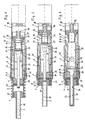
- Fig. 1 shows sections of the section on the barrel side of a powder-operated bolt-setting tool in its initial position.
- FIG 2 and 3 show the detail of the bolt gun the bolt setting process or at the end of the bolt setting process.
- the powder powered bolt gun shown includes a barrel guide sleeve 1, the mouth side of a sleeve-shaped insert 2 records.
- the insert 2 takes a slidable therein Bolt guide 3, which is provided with a shoulder 4, which in the starting position of Fig. 1 on an inward flange portion 5 of a screwed on the muzzle on the barrel guide sleeve 1 Threaded piece 6 rests.
- a coil spring 9 is clamped prestresses the bolt guide 3 in the starting position of FIG. 1.
- the bolt guide 3 has a bore 10 for receiving a to be set bolt, which extends on the side facing away from the mouth is displaceable around the mouth end of a barrel front part 11 record during use 2 as a safety stop for the barrel front 11 is used when the device is operated without loading a bolt should be.
- a rear barrel part 12 is provided, which with a Extension 13 inserted into the barrel front part 11 and in which a piston receptacle 14 and a combustion chamber adjacent to a conical tread 15 is formed.
- a cartridge bearing 16 is provided for receiving a cartridge, with the Cartridge bearing 16 has a narrowing bore opening into the running floor 15 17 connects.
- a cartridge is located adjacent to the cartridge store 16 Closure piece 18 having a cartridge band guide.
- the rear barrel part 12 is via one or more tie rods 19th connected to the bolt guide 3 such that the distance between the two within predetermined limits determined by an axial groove 20 be in which the mouth end of the pull rod 19 slidably is, may vary.
- the pull rod 19 advantageously has hook-shaped ends with which they into the axial groove 20 or a corresponding Recess is mounted on the barrel rear part 12.
- a piston 21 is also provided, which has a piston head 22 and has a piston shaft 23.
- the piston skirt 23 is up to the mouth side the bore 10 of the pin guide 3 is displaceable (Fig. 3).
- the Piston head 22 has a section 24 which is in the starting position is received by the piston receptacle 14 of the rear barrel part 12, and a section 25 with an enlarged diameter by the barrel guide bore 26 of the barrel front part 11 is guided.
- the piston 21 has a transition piece a conical mouth-side end 27, which has a conical receptacle 28 is assigned at the mouth end of the barrel front part 11, and one adjoining cylindrical section 29 adjacent to Section 25.
- a damping disk 30 can be arranged his.
- the barrel front part 11 is on its with the barrel rear part 12 engaging end with several, distributed over its circumference Vent slots 31 provided in the starting position of FIG. 1st are practically covered by the section 25 of the piston 21.
- the ventilation slots 31 open into a by a twist 32 at the end of Barrel front part 11 formed and surrounded by the barrel guide sleeve 1 Annulus.
- the barrel guide sleeve 1 has corresponding ventilation openings 33 provided so that the ventilation slots 31 with the outside are connected.
- the bolt guide 3 takes a corresponding one for setting the bolts Bolt (not shown).
- the bolt gun is on a Wall or the like, in which the bolt is to be placed, placed and brought into firing position by pressing against the wall (Fig. 2).
- the bolt guide 3 against the force of the coil spring 9 in the barrel guide sleeve 1 until the coil spring 9 is compressed, indented so that barrel front part 11 and barrel rear part 12 backwards are moved so that the cartridge bearing 16 receives a cartridge and is brought into the firing position with respect to the closure piece 18.
- the ventilation slots are 31 already released for the escape of combustion gases, so that the piston back is connected to the outside, reducing the pressure falls behind the piston 21 accordingly. This release then takes place when the portion 24 of the piston head 22 emerged from the rear barrel 12 and the piston 21 is accelerated accordingly.
- the volume of air compressed in the annular space 34 is due to the sealing of the annular space 34 by the section 25 of the piston 21 opposite the barrel guide bore 26 and through the piston skirt 23 and the adjoining conical section 27 on the outlet side of the barrel front part 11 is built up and intercepts the piston 21.
- the volume of air compressed in the annular space 34 expands due to the pressure drop on the back of the piston thereby returning the piston 21 to its initial position in which the section 24 of the piston head 22 is received by the barrel rear part 12 and the portion 25 of the piston head 22 adjacent to the barrel rear part 12 is located.
- Leakage losses on the sealing surfaces must of course be so low be held that the air volume acting as an air spring is sufficient Force can be applied to the piston 21 in its initial position attributed.
Claims (8)
- Appareil de mise en place de boulons fonctionnant sous l'action d'une poudre, doté d'un canon (11, 12) guidé dans une douille de guidage (1), susceptible de coopérer avec une culasse (18), canon dont l'alésage de guidage (26) reçoit un piston (21) qui présente une tige (23) et une tête (22) et qui est doté d'un logement (16) pour cartouches débouchant sur la face détournée de l'ouverture, caractérisé en ce que le canon (11, 12) présente des ouïes de ventilation (31) sur sa face tournée vers le logement (16) pour cartouches, lesquelles sont dégagées par la tête de piston (22) lors de la mise en place des boulons avant que le piston (21) n'atteigne sa position finale du côté de la bouche de sortie, position dans laquelle un coussin de gaz est comprimé entre la tête de piston (22) et le canon (11, 12) et repousse ensuite le piston (21) dans sa position initiale.
- Appareil selon la revendication 1, caractérisé en ce que le canon (11, 12) présente une empreinte conique (28) pour une section conique (27) située à l'extrémité de la tige (23) du piston.
- Appareil selon la revendication 1 ou 2, caractérisé en ce que le canon est composé d'une partie avant de canon (11) et d'une partie arrière de canon (12), qui sont engagées l'une dans l'autre et axialement mobiles l'une par rapport à l'autre.
- Appareil selon la revendication 3, caractérisé en ce que la partie avant (11) et la partie arrière (12) de canon servent à guider chacune une section (24, 25) de la tête de piston (22), les ouïes de ventilation (31) étant disposées dans la partie avant de canon (11) avoisinant la partie arrière de canon (12).
- Appareil selon la revendication 4, caractérisé en ce que la section arrière (24) de la tête de piston (22) présente un diamètre inférieur à sa section avant (25).
- Appareil selon l'une quelconque des revendications 1 à 5, caractérisé en ce qu'un moyen de guidage de boulon (3), susceptible d'être traversé par la tige de piston (23), est guidé dans la douille de guidage (1) du canon du côté de la bouche de sortie et comprimé par rapport à celle-ci par une précontrainte de ressort (9), le moyen de guidage de boulon (3) et le canon (11, 12) étant accouplés l'un par rapport à l'autre de telle façon qu'ils soient mobiles axialement entre eux sur une distance déterminée et que le moyen de guidage de boulon (3) puisse amener le canon (11, 12) dans sa position initiale hors de coopération avec la culasse (18) en libérant la précontrainte de ressort (9).
- Appareil selon la revendication 4, caractérisé en ce que le moyen de guidage (3) de canon est accouplé au canon (11, 12) par au moins une barre de traction (19).
- Appareil selon l'une quelconque des revendications 1 à 7, caractérisé en ce que le canon (11, 12) est doté d'un disque d'absorption (30) au niveau de sa face frontale du côté de la bouche de sortie.
Applications Claiming Priority (3)
| Application Number | Priority Date | Filing Date | Title |
|---|---|---|---|
| DE19617671 | 1996-05-03 | ||
| DE19617671A DE19617671C1 (de) | 1996-05-03 | 1996-05-03 | Pulverkraftbetriebenes Bolzensetzgerät |
| US09/094,138 US6123242A (en) | 1996-05-03 | 1998-06-09 | Explosive powder charge operated bolt-setting tool |
Publications (3)
| Publication Number | Publication Date |
|---|---|
| EP0805002A2 EP0805002A2 (fr) | 1997-11-05 |
| EP0805002A3 EP0805002A3 (fr) | 1998-01-14 |
| EP0805002B1 true EP0805002B1 (fr) | 2001-07-04 |
Family
ID=26025332
Family Applications (1)
| Application Number | Title | Priority Date | Filing Date |
|---|---|---|---|
| EP97107295A Expired - Lifetime EP0805002B1 (fr) | 1996-05-03 | 1997-05-02 | Appareil de scellement de chevilles actionné par la poudre |
Country Status (5)
| Country | Link |
|---|---|
| US (1) | US6123242A (fr) |
| EP (1) | EP0805002B1 (fr) |
| AT (1) | ATE202737T1 (fr) |
| DE (2) | DE19617671C1 (fr) |
| ES (1) | ES2171239T3 (fr) |
Families Citing this family (19)
| Publication number | Priority date | Publication date | Assignee | Title |
|---|---|---|---|---|
| AUPP770598A0 (en) * | 1998-12-14 | 1999-01-14 | Ramset Fasteners (Aust.) Pty. Limited | Power actuated tools |
| DE10105196B4 (de) * | 2001-02-06 | 2013-09-26 | Hilti Aktiengesellschaft | Setzgerät |
| DE10105881B4 (de) * | 2001-02-09 | 2004-01-15 | Hilti Ag | Kolbenhalterung |
| US6705409B2 (en) | 2001-03-22 | 2004-03-16 | Chicago Pneumatic Tool Company | Reciprocating tool having a piston retaining system |
| US6679411B2 (en) * | 2001-12-21 | 2004-01-20 | Illinois Tool Works Inc. | Piston retention system for a fastener driving tool |
| DE10259817B4 (de) * | 2002-12-19 | 2015-03-05 | Hilti Aktiengesellschaft | Brennkraftbetriebenes Setzgerät für Befestigungselemente |
| DE10259567A1 (de) * | 2002-12-19 | 2004-07-01 | Hilti Ag | Brennkraftbetriebenes Setzgerät |
| DE10341385B4 (de) * | 2003-09-05 | 2016-06-23 | Hilti Aktiengesellschaft | Setzgerät |
| US7287679B2 (en) * | 2004-07-28 | 2007-10-30 | Powers Products Iii, Llc | Powder activated setting tool piston retainer arrangement and method |
| JP4721923B2 (ja) * | 2005-07-13 | 2011-07-13 | 日東工器株式会社 | 空気圧式駆動工具 |
| DE102005000106B4 (de) * | 2005-08-25 | 2014-02-27 | Hilti Aktiengesellschaft | Setzgerät |
| DE102005000114A1 (de) * | 2005-09-13 | 2007-03-15 | Hilti Ag | Setzgerät |
| DE102005000113B4 (de) * | 2005-09-13 | 2014-03-27 | Hilti Aktiengesellschaft | Setzgerät |
| DE102005000134A1 (de) * | 2005-10-05 | 2007-04-12 | Hilti Ag | Brennkraftbetriebenes Setzgerät |
| US20080251561A1 (en) * | 2007-04-13 | 2008-10-16 | Chad Eades | Quick connect base plate for powder actuated tool |
| CN203092484U (zh) * | 2013-02-22 | 2013-07-31 | 郭景辉 | 一种用于射钉枪的卸力装置 |
| EP2886257A1 (fr) * | 2013-12-18 | 2015-06-24 | HILTI Aktiengesellschaft | Appareil d'enfoncement |
| EP2923797A1 (fr) * | 2014-03-28 | 2015-09-30 | HILTI Aktiengesellschaft | Cloueur à poudre |
| US11448025B2 (en) * | 2018-02-23 | 2022-09-20 | Hunting Titan, Inc. | Impact resistant material in setting tool |
Family Cites Families (18)
| Publication number | Priority date | Publication date | Assignee | Title |
|---|---|---|---|---|
| US2877750A (en) * | 1957-05-29 | 1959-03-17 | Olin Mathieson | Hammer and buffer mechanism |
| US3255942A (en) * | 1964-06-12 | 1966-06-14 | Star Expansion Ind Corp | Piston tool with fastener resetting arrangement |
| NO116033B (fr) * | 1966-09-27 | 1969-01-13 | Gunnebo Bruks Ab | |
| GB1388835A (en) * | 1971-06-01 | 1975-03-26 | British Screw Co Ltd | Explosive powder actuated devices |
| US3744240A (en) * | 1971-11-05 | 1973-07-10 | Olin Corp | Fastener driving tool |
| US3815475A (en) * | 1972-11-20 | 1974-06-11 | Signode Corp | Fastener driving tool with improved piston return |
| US4358041A (en) * | 1980-06-12 | 1982-11-09 | Olin Corporation | Powder-actuated tool with power adjustment and angle-fire control |
| US4711851A (en) * | 1984-05-21 | 1987-12-08 | State University Of New York | Test apparatus for determining a metabolic characteristic of microorganisms |
| DE3540953A1 (de) * | 1985-11-19 | 1987-05-21 | Hilti Ag | Pulverkraftbetriebenes bolzensetzgeraet |
| US4753151A (en) * | 1986-06-27 | 1988-06-28 | Lockheed Corporation | Self-retracting ballistic actuator system |
| FR2608493B1 (fr) * | 1986-12-23 | 1994-09-02 | Prospection & Inventions | Appareil de scellement a tir indirect |
| DE3819813A1 (de) * | 1988-06-10 | 1989-12-14 | Hilti Ag | Pulverkraftbetriebenes setzgeraet |
| DE4022674A1 (de) * | 1990-07-17 | 1992-01-23 | Hilti Ag | Pulverkraftbetriebenes setzgeraet |
| FR2690370B1 (fr) * | 1992-04-24 | 1994-07-29 | Prospection & Inventions | Appareil pour la pose d'elements de fixation, a masselotte, cliquet de rappel de masselotte et guide-tampon pivotant. |
| DE4313504A1 (de) * | 1993-04-24 | 1994-10-27 | Hilti Ag | Pulverkraftbetriebenes Setzgerät |
| JP3346041B2 (ja) * | 1994-07-20 | 2002-11-18 | アイシン精機株式会社 | アンチスキッド制御装置 |
| DE19547859A1 (de) * | 1995-12-21 | 1997-06-26 | Hilti Ag | Pulverkraftbetriebenes Setzgerät |
| FR2746690B1 (fr) * | 1996-03-26 | 1998-05-29 | Spit Soc Prospect Inv Techn | Appareil d'entrainement de tampon par masselotte a retour automatique en position du tir |
-
1996
- 1996-05-03 DE DE19617671A patent/DE19617671C1/de not_active Expired - Fee Related
-
1997
- 1997-05-02 EP EP97107295A patent/EP0805002B1/fr not_active Expired - Lifetime
- 1997-05-02 ES ES97107295T patent/ES2171239T3/es not_active Expired - Lifetime
- 1997-05-02 DE DE59703935T patent/DE59703935D1/de not_active Expired - Fee Related
- 1997-05-02 AT AT97107295T patent/ATE202737T1/de not_active IP Right Cessation
-
1998
- 1998-06-09 US US09/094,138 patent/US6123242A/en not_active Expired - Fee Related
Also Published As
| Publication number | Publication date |
|---|---|
| ATE202737T1 (de) | 2001-07-15 |
| DE59703935D1 (de) | 2001-08-09 |
| EP0805002A3 (fr) | 1998-01-14 |
| EP0805002A2 (fr) | 1997-11-05 |
| DE19617671C1 (de) | 1997-10-09 |
| ES2171239T3 (es) | 2002-09-01 |
| US6123242A (en) | 2000-09-26 |
Similar Documents
| Publication | Publication Date | Title |
|---|---|---|
| EP0805002B1 (fr) | Appareil de scellement de chevilles actionné par la poudre | |
| EP0490252B1 (fr) | Dispositif pour l'allumage d'une charge propulsive; cartouches et magasin pour des cartouches susceptibles d'être allumées adiabatiquement, notamment pour des appareils de clouage par explosion | |
| DE2750945A1 (de) | Rueckstossdaempfer fuer schusswaffen | |
| DE3231405A1 (de) | Gasdruckbetaetigte schusswaffe | |
| EP0805003B1 (fr) | Appareil de scellement de chevilles actionné par la poudre | |
| DE19547859A1 (de) | Pulverkraftbetriebenes Setzgerät | |
| EP1712870A2 (fr) | Arme à air comprimé | |
| EP0732178B1 (fr) | Outil de scellement de chevilles | |
| DE102013224209A1 (de) | Patrone zum Einsetzen in eine Schusswaffe eines Waffensimulators und umgebaute Schusswaffe eines Waffensimulators mit einer solchen Patrone | |
| DE10259817A1 (de) | Brennkraftbetriebenes Setzgerät für Befestigungselemente | |
| DE2840216A1 (de) | Geschosspatrone und munition fuer kleinkaliberwaffen o.dgl. | |
| DE3150675A1 (de) | Zuendvorrichtung fuer verbrennungsmotoren mit innerer verbrennung und selbstzuendung | |
| DE3102801A1 (de) | "kraftstoffeinspritzpumpe" | |
| DE1628013B2 (de) | Bolzensetzgeraet fuer eine huelsenlose, als feststoff-formkoerper ausgebildete treibladung | |
| DE4009050C2 (fr) | ||
| DE3005919C2 (fr) | ||
| DE2319152A1 (de) | Werkzeug, vorzugsweise pistole, zum einschiessen von befestigungsmitteln | |
| EP0754929A1 (fr) | Dispositif pour fixation d'une douille à un projectile | |
| AT500036B1 (de) | Verschluss für eine hülsenlose patrone | |
| DE3211535C2 (de) | Luftgewehr | |
| AT355524B (de) | Patronenkammer fuer ein bolzensetzgeraet | |
| DE19818714C2 (de) | Blockiervorrichtung für bewegliche Anschlüsse von Schalldämpfern an halbautomatischen Waffen | |
| DE2053098C3 (de) | Hydropneumatischer Rohrvorholer für Geschütze | |
| DE2105223A1 (de) | Rakete mit einem Raketenmotor und einem Geschoßkopf und mit einer Vorrichtung zum Verbinden des Raketenmotors mit dem Geschoß kopf | |
| DE1478924C (de) | Brennkraftbolzensetzer |
Legal Events
| Date | Code | Title | Description |
|---|---|---|---|
| PUAI | Public reference made under article 153(3) epc to a published international application that has entered the european phase |
Free format text: ORIGINAL CODE: 0009012 |
|
| AK | Designated contracting states |
Kind code of ref document: A2 Designated state(s): AT CH DE ES FI FR GB IT LI SE |
|
| PUAL | Search report despatched |
Free format text: ORIGINAL CODE: 0009013 |
|
| AK | Designated contracting states |
Kind code of ref document: A3 Designated state(s): AT CH DE ES FI FR GB IT LI SE |
|
| 17P | Request for examination filed |
Effective date: 19980116 |
|
| RAP1 | Party data changed (applicant data changed or rights of an application transferred) |
Owner name: BERNER GMBH |
|
| GRAG | Despatch of communication of intention to grant |
Free format text: ORIGINAL CODE: EPIDOS AGRA |
|
| GRAG | Despatch of communication of intention to grant |
Free format text: ORIGINAL CODE: EPIDOS AGRA |
|
| 17Q | First examination report despatched |
Effective date: 19991001 |
|
| GRAG | Despatch of communication of intention to grant |
Free format text: ORIGINAL CODE: EPIDOS AGRA |
|
| GRAH | Despatch of communication of intention to grant a patent |
Free format text: ORIGINAL CODE: EPIDOS IGRA |
|
| GRAH | Despatch of communication of intention to grant a patent |
Free format text: ORIGINAL CODE: EPIDOS IGRA |
|
| GRAA | (expected) grant |
Free format text: ORIGINAL CODE: 0009210 |
|
| AK | Designated contracting states |
Kind code of ref document: B1 Designated state(s): AT CH DE ES FI FR GB IT LI SE |
|
| RAP1 | Party data changed (applicant data changed or rights of an application transferred) |
Owner name: BERNER GMBH |
|
| REF | Corresponds to: |
Ref document number: 202737 Country of ref document: AT Date of ref document: 20010715 Kind code of ref document: T |
|
| REG | Reference to a national code |
Ref country code: CH Ref legal event code: EP |
|
| REF | Corresponds to: |
Ref document number: 59703935 Country of ref document: DE Date of ref document: 20010809 |
|
| ITF | It: translation for a ep patent filed |
Owner name: STUDIO TORTA S.R.L. |
|
| GBT | Gb: translation of ep patent filed (gb section 77(6)(a)/1977) |
Effective date: 20010921 |
|
| ET | Fr: translation filed | ||
| REG | Reference to a national code |
Ref country code: CH Ref legal event code: NV Representative=s name: TROESCH SCHEIDEGGER WERNER AG |
|
| REG | Reference to a national code |
Ref country code: GB Ref legal event code: IF02 |
|
| PG25 | Lapsed in a contracting state [announced via postgrant information from national office to epo] |
Ref country code: GB Free format text: LAPSE BECAUSE OF NON-PAYMENT OF DUE FEES Effective date: 20020502 Ref country code: FI Free format text: LAPSE BECAUSE OF NON-PAYMENT OF DUE FEES Effective date: 20020502 Ref country code: AT Free format text: LAPSE BECAUSE OF NON-PAYMENT OF DUE FEES Effective date: 20020502 |
|
| PG25 | Lapsed in a contracting state [announced via postgrant information from national office to epo] |
Ref country code: SE Free format text: LAPSE BECAUSE OF NON-PAYMENT OF DUE FEES Effective date: 20020503 Ref country code: ES Free format text: LAPSE BECAUSE OF NON-PAYMENT OF DUE FEES Effective date: 20020503 |
|
| PLBE | No opposition filed within time limit |
Free format text: ORIGINAL CODE: 0009261 |
|
| STAA | Information on the status of an ep patent application or granted ep patent |
Free format text: STATUS: NO OPPOSITION FILED WITHIN TIME LIMIT |
|
| PG25 | Lapsed in a contracting state [announced via postgrant information from national office to epo] |
Ref country code: LI Free format text: LAPSE BECAUSE OF NON-PAYMENT OF DUE FEES Effective date: 20020531 Ref country code: CH Free format text: LAPSE BECAUSE OF NON-PAYMENT OF DUE FEES Effective date: 20020531 |
|
| 26N | No opposition filed | ||
| REG | Reference to a national code |
Ref country code: ES Ref legal event code: FG2A Ref document number: 2171239 Country of ref document: ES Kind code of ref document: T3 |
|
| PG25 | Lapsed in a contracting state [announced via postgrant information from national office to epo] |
Ref country code: DE Free format text: LAPSE BECAUSE OF NON-PAYMENT OF DUE FEES Effective date: 20021203 |
|
| GBPC | Gb: european patent ceased through non-payment of renewal fee |
Effective date: 20020502 |
|
| EUG | Se: european patent has lapsed | ||
| REG | Reference to a national code |
Ref country code: CH Ref legal event code: PL |
|
| PG25 | Lapsed in a contracting state [announced via postgrant information from national office to epo] |
Ref country code: FR Free format text: LAPSE BECAUSE OF NON-PAYMENT OF DUE FEES Effective date: 20030131 |
|
| REG | Reference to a national code |
Ref country code: FR Ref legal event code: ST |
|
| REG | Reference to a national code |
Ref country code: ES Ref legal event code: FD2A Effective date: 20030611 |
|
| PG25 | Lapsed in a contracting state [announced via postgrant information from national office to epo] |
Ref country code: IT Free format text: LAPSE BECAUSE OF NON-PAYMENT OF DUE FEES;WARNING: LAPSES OF ITALIAN PATENTS WITH EFFECTIVE DATE BEFORE 2007 MAY HAVE OCCURRED AT ANY TIME BEFORE 2007. THE CORRECT EFFECTIVE DATE MAY BE DIFFERENT FROM THE ONE RECORDED. Effective date: 20050502 |