EP0804315B1 - Machine-outil - Google Patents
Machine-outil Download PDFInfo
- Publication number
- EP0804315B1 EP0804315B1 EP95904526A EP95904526A EP0804315B1 EP 0804315 B1 EP0804315 B1 EP 0804315B1 EP 95904526 A EP95904526 A EP 95904526A EP 95904526 A EP95904526 A EP 95904526A EP 0804315 B1 EP0804315 B1 EP 0804315B1
- Authority
- EP
- European Patent Office
- Prior art keywords
- coupling element
- screw driver
- driver according
- output shaft
- tool
- Prior art date
- Legal status (The legal status is an assumption and is not a legal conclusion. Google has not performed a legal analysis and makes no representation as to the accuracy of the status listed.)
- Expired - Lifetime
Links
Images


Classifications
-
- B—PERFORMING OPERATIONS; TRANSPORTING
- B23—MACHINE TOOLS; METAL-WORKING NOT OTHERWISE PROVIDED FOR
- B23D—PLANING; SLOTTING; SHEARING; BROACHING; SAWING; FILING; SCRAPING; LIKE OPERATIONS FOR WORKING METAL BY REMOVING MATERIAL, NOT OTHERWISE PROVIDED FOR
- B23D29/00—Hand-held metal-shearing or metal-cutting devices
- B23D29/005—Hand-held metal-shearing or metal-cutting devices for cutting sheets
-
- B—PERFORMING OPERATIONS; TRANSPORTING
- B23—MACHINE TOOLS; METAL-WORKING NOT OTHERWISE PROVIDED FOR
- B23D—PLANING; SLOTTING; SHEARING; BROACHING; SAWING; FILING; SCRAPING; LIKE OPERATIONS FOR WORKING METAL BY REMOVING MATERIAL, NOT OTHERWISE PROVIDED FOR
- B23D47/00—Sawing machines or sawing devices working with circular saw blades, characterised only by constructional features of particular parts
- B23D47/12—Sawing machines or sawing devices working with circular saw blades, characterised only by constructional features of particular parts of drives for circular saw blades
-
- B—PERFORMING OPERATIONS; TRANSPORTING
- B23—MACHINE TOOLS; METAL-WORKING NOT OTHERWISE PROVIDED FOR
- B23Q—DETAILS, COMPONENTS, OR ACCESSORIES FOR MACHINE TOOLS, e.g. ARRANGEMENTS FOR COPYING OR CONTROLLING; MACHINE TOOLS IN GENERAL CHARACTERISED BY THE CONSTRUCTION OF PARTICULAR DETAILS OR COMPONENTS; COMBINATIONS OR ASSOCIATIONS OF METAL-WORKING MACHINES, NOT DIRECTED TO A PARTICULAR RESULT
- B23Q11/00—Accessories fitted to machine tools for keeping tools or parts of the machine in good working condition or for cooling work; Safety devices specially combined with or arranged in, or specially adapted for use in connection with, machine tools
- B23Q11/04—Arrangements preventing overload of tools, e.g. restricting load
-
- B—PERFORMING OPERATIONS; TRANSPORTING
- B23—MACHINE TOOLS; METAL-WORKING NOT OTHERWISE PROVIDED FOR
- B23Q—DETAILS, COMPONENTS, OR ACCESSORIES FOR MACHINE TOOLS, e.g. ARRANGEMENTS FOR COPYING OR CONTROLLING; MACHINE TOOLS IN GENERAL CHARACTERISED BY THE CONSTRUCTION OF PARTICULAR DETAILS OR COMPONENTS; COMBINATIONS OR ASSOCIATIONS OF METAL-WORKING MACHINES, NOT DIRECTED TO A PARTICULAR RESULT
- B23Q5/00—Driving or feeding mechanisms; Control arrangements therefor
- B23Q5/02—Driving main working members
- B23Q5/04—Driving main working members rotary shafts, e.g. working-spindles
-
- B—PERFORMING OPERATIONS; TRANSPORTING
- B24—GRINDING; POLISHING
- B24B—MACHINES, DEVICES, OR PROCESSES FOR GRINDING OR POLISHING; DRESSING OR CONDITIONING OF ABRADING SURFACES; FEEDING OF GRINDING, POLISHING, OR LAPPING AGENTS
- B24B47/00—Drives or gearings; Equipment therefor
- B24B47/10—Drives or gearings; Equipment therefor for rotating or reciprocating working-spindles carrying grinding wheels or workpieces
-
- B—PERFORMING OPERATIONS; TRANSPORTING
- B25—HAND TOOLS; PORTABLE POWER-DRIVEN TOOLS; MANIPULATORS
- B25B—TOOLS OR BENCH DEVICES NOT OTHERWISE PROVIDED FOR, FOR FASTENING, CONNECTING, DISENGAGING OR HOLDING
- B25B21/00—Portable power-driven screw or nut setting or loosening tools; Attachments for drilling apparatus serving the same purpose
- B25B21/02—Portable power-driven screw or nut setting or loosening tools; Attachments for drilling apparatus serving the same purpose with means for imparting impact to screwdriver blade or nut socket
Definitions
- the invention relates to a machine tool in the form of a Screwdriver with a drive comprising an output shaft, which performs an intermittent rotational movement, and which over a one-way clutch with a tool drive shaft for driving a tool is coupled.
- Such a machine tool can be used as a screwdriver known from US-A-2 392 097.
- the aforementioned machine tool enables transmission a relatively large torque on the tool, does not allow precise shutdown of the drive Reaching a predetermined torque.
- the invention is therefore based on the object, a To create screwdrivers that can be used with the high tool torque with a relatively low one
- Has reaction torque and a shutdown as precise as possible of the screwdriver when a predetermined torque is reached enables.
- a shutdown device to switch off the drive when a predetermined torque and a separating device for separating the tool drive shaft are provided by the drive that the Separating device rotatable with the tool drive shaft connected connected first coupling element which with the Output side of a one-way clutch can be coupled, and a has a second coupling element which is non-rotatable with the tool drive shaft is connected between the first coupling element and the second coupling element, an intermediate coupling element is arranged with the second coupling element forms a driving clutch over which the intermediate coupling element under load towards the first coupling element is displaceable that the intermediate coupling element with the first Coupling element with axial displacement of the intermediate coupling element disengageable separating clutch forms, and that the intermediate coupling element in the direction of the second Coupling element is spring loaded.
- the object of the invention is completely achieved in this way, because high torque with relatively low drive power can be achieved because the reaction moment due to the novel Drive is kept relatively low and by the structure the switch-off device and the separating device for separating the tool drive shaft a very precise adherence to a can reach the specified tightening torque.
- a screwdriver according to the invention is particularly notable characterized in that the tightening torque is in a wide range can be preset very precisely, provided a corresponding one Torque shutdown is provided.
- reaction torque compared to conventional screwdrivers significantly reduced with shutdown device. Be at the same time screws or nuts to be tightened or loosened considerably less stressed than when working with conventional pulse or Impact wrenches.
- an actuator for presetting the Shutdown torque may be provided.
- the intermittent rotary movement of the drive shaft can basically be generated in different ways.
- the rotary movement of a drive motor via an oscillation drive into an oscillating rotary movement be implemented.
- a rotary magnet or a Stepper motor are used, the corresponding one Voltage pulse train is driven.
- the drive of the machine tool comprises a motor coupled to an oscillation drive is a rotary motion of the motor shaft into an oscillating Rotational movement of the one-way clutch driving Output shaft is implemented.
- oscillation drives are basically known and can be used advantageously for this version.
- the machine tool according to the invention has the advantage that due to the oscillating around a fixed swivel axis Rotary movement of the output shaft of the oscillation drive practically reaction-free work results because of every rotary movement the output shaft of the oscillation drive in the direction of rotation the tool has an equally long rotational movement in opposite directions Direction follows.
- the amplitude of the oscillation movement can fixed axis of rotation adapted to the respective application become.
- the frequency of the oscillation drive can be changed be carried out to regulate the performance of the tool.
- the oscillation drive can basically be different Species.
- the oscillation drive comprises an eccentric element driven by the motor shaft, from which a pivoting element is driven, which is connected to the output shaft is rotatably connected.
- An electric motor a compressed air motor, a hydraulic motor or the like may be provided.
- Another way of generating an intermittent Rotary movement of the output shaft consists in the use of a Rotary magnet that generates a voltage pulse train the intermittent rotary movement is applied.
- This measure has the advantage that it is particularly simple Design results, since only a rotary magnet is required, of the corresponding control electronics with a voltage pulse train is acted upon.
- a device rotating magnet can be used as the rotating magnet are provided that this with a restoring force against the Direction of rotation is applied, which generates about a spring can be.
- the rotating magnet can also be used as a bidirectional rotating magnet be formed, if provided on a return spring should be dispensed with.
- the electronic Control generate a corresponding reset pulse.
- Control of performance can be done in a simple manner be achieved that the pulse energy of the voltage pulse train with constant frequency by means of pulse width modulation (PWM) is adjustable.
- PWM pulse width modulation
- the torque transferred to the tool depends on the pulse energy.
- the Pulse frequency can be changed to the performance of the tool to control.
- the frequency can only be used to a certain extent Frame can be changed because of the mechanically vibrating system on the one hand could be brought into resonance or on the other hand if the frequency is too high, the rotating magnet stops the result could be.
- the output shaft taken up by two spaced apart bearings, wherein the one bearing fixed in the radial direction of the output shaft is, while the other bearing against radial preload is arranged displaceably, the output shaft a sensor element is assigned to the drive when it occurs switch off a radial displacement.
- an actuator for generating an adjustable Preload is provided to adjust the tripping torque to enable.
- the other bearing can be taken up by a sliding guide be a displacement in the radial direction of the output shaft allowed.
- a first one-way clutch and clockwise a second one-way clutch that moves counterclockwise Arranged one behind the other in the axial direction, with a switching element is provided to choose either either the first or the second one-way clutch with the tool drive shaft couple.
- the switching element designed as a sliding sleeve in the axial direction of the output shaft is slidably mounted, in a first in Direction on the tool drive shaft advanced position the sliding sleeve, the first one-way clutch over the sliding sleeve is coupled to the tool drive shaft, and wherein in a second retracted position of the sliding sleeve the second Overrunning clutch is coupled to the tool drive shaft.
- the first coupling element and the intermediate coupling element formed coupling straight cam with a vertical to the driving flank on a radial plane the elements on, as well as offset cams with a straight Section in which the driving flank is perpendicular to a Radial plane extends, and with an oblique, to the straight section adjoining section in which the Driving flank extends obliquely to a radial plane on one of the other elements.
- This cam shape is used when the machine tool starts up engagement of the clutch is ensured. This should the slope of the sloping portions of the offset cams be dimensioned so that first the intermediate coupling element with its straight cams between the straight cam sections of the first coupling element engages before the intermediate coupling element under the effect of the transmitted torque is moved towards the second coupling element.
- the second Coupling element extending in a radial direction Projection on that with a guide curve of the intermediate coupling element, that extends obliquely to a radial plane, cooperates.
- This measure has the advantage of being particularly simple and Construction of the driving clutch that can be manufactured cost-effectively.
- the Radially extending projection by a cross pin be formed, which passes through the output shaft in the radial direction.
- the driving clutch can be particularly simple Way by a cross pin fixable in a radial bore in connection with an arranged obliquely to a radial plane Realize leadership curve.
- the slope of the guide curve should greater than the inclination of the oblique cam sections of the Intermediate clutch element to engage the separating clutch ensure at the beginning.
- Fig. 1 is a machine tool according to the invention, the used as a screwdriver, extremely schematic shown and designated overall by the number 160.
- the machine tool 160 includes an electric motor 162, an output shaft 180 via an oscillation drive 164 drives.
- the drive shaft 180 is either via a first one-way clutch 188, which drives clockwise, or via a second one-way clutch 190, which is counterclockwise entrains, connectable to a tool drive shaft 200 to a inserted into a tool holder 202 of the tool drive shaft 200 Power tool.
- a first one-way clutch 188 which drives clockwise
- a second one-way clutch 190 which is counterclockwise entrains, connectable to a tool drive shaft 200 to a inserted into a tool holder 202 of the tool drive shaft 200 Power tool.
- To switch between the first one-way clutch 188 and the second one-way clutch 190 So to switch between clockwise and counterclockwise rotation, is used switching element designated overall by the number 184.
- the oscillation drive 164 comprises according to FIGS. 1 and 4 on the motor shaft 168, which protrude from the motor housing End on a flanged holder 166 by means of a Bearing 181 is mounted, arranged eccentric element 170 Eccentric element 170 is enclosed by a needle sleeve 172 which serves as a pivot bearing.
- On the output shaft 180 is a swivel element 174 non-rotatably arranged, in the direction of the motor shaft 168 protruding section through a U-shaped cutout two swivel arms 176 are formed, between which the Needle sleeve 172 is enclosed from both sides.
- the switching element 184 is designed as a cylindrical switching sleeve, which is axially displaceably mounted on the output shaft 180 is.
- the switching sleeve 184 are the first one after the other One-way clutch 188, a bearing 186 and the second one-way clutch 190 arranged.
- the switching sleeve 184 is with the bearing 186 axially displaceable on the output shaft 180 and with a second bearing 196, which at its front, the tool holder 202 facing end is provided on the tool drive shaft 200 slidable in the axial direction.
- Fig. 1 In the position shown in Fig. 1 is the Switch sleeve 184 in a first, in the direction of the tool holder 202 advanced position in which its the tool holder 202 facing end face with radial Cam 205 is provided, between cam 207 (Fig. 3a, b) one first coupling element 208 of a subsequent overall engages with the separator designated by number 198, with which they form a dog clutch 206.
- the torque is therefore in the position shown in FIG. 1 from the output shaft 180 via the first one-way clutch 188 transferred to the shift sleeve 184, from which the drive torque via the dog clutch 206 and the separator 198 is transmitted to the tool drive shaft 200.
- the second one-way clutch 190 is inoperative.
- the tool drive shaft 200 has a smaller diameter than the output shaft 180 and is on the output shaft 180 facing end against this by means of a thrust bearing stored, which is indicated by the number 192 and in simplest case is designed as a ball, in corresponding Recesses of the output shaft 180 and the tool drive shaft 200 is held.
- the tool drive shaft 200 is on its Output shaft 180 facing end further from a cross pin 194 penetrates, the two ends of which laterally radially from the tool drive shaft 200 protrude.
- a cross pin 194 penetrates, the two ends of which laterally radially from the tool drive shaft 200 protrude.
- the ends of cross pin 194 freely within the second one-way clutch 190 rotate so that it is complete has no function. If, on the other hand, the sliding sleeve 184 to the right in the direction of the oscillation drive 164 in the pushed back position shown in FIG this cross pin 194 in a longitudinal slot 197, which is between the second bearing 196 and the second one-way clutch 190 extends. This creates a positive connection between the switching sleeve 184 and the tool drive shaft 200 in the position shown in FIG.
- the separating device 198 consists of the first coupling element 208, from an intermediate coupling element 210 and from a second Coupling element 212. There is between the first coupling element 208 and the intermediate coupling element 210 a spring element 214 arranged, which is designed as a coil spring and that Intermediate coupling element 210 against the second coupling element 212 presses.
- the first clutch element 208 is a clutch disc trained and rotatable, but not in the axial direction slidably arranged on the tool drive shaft 200.
- the first coupling element 208 has the radially extending side facing the switching sleeve 184 Cam body 207 to match the corresponding cam bodies 205 a claw coupling on the end face of the switching sleeve 184 206 to form the in the clockwise position shown in Fig. 6 a transmission of the torque from the shift sleeve 184 ensures on the first coupling element 208.
- first coupling element 208 On the side of the intermediate coupling element 210 first coupling element 208 are stepped cam bodies 209 provided a straight, extending from the face have extending portion in which the driving flank 215 extends perpendicular to a radial plane to which a sloping section follows, in which the driving flank 216 runs obliquely to a radial plane.
- This weird Section of each cam 209 runs on the end face 217 of the cam, which extends parallel to a radial plane.
- the intermediate coupling element 210 has the first on it Coupling element 208 facing side straight cam 211, which extend in the radial direction.
- the second coupling element 212 is designed as a cross pin, which radially penetrates the tool drive shaft 200 and protrudes from it with both ends.
- the intermediate coupling element 210 which is freely rotatable and axially displaceable the tool drive shaft 200 is arranged on it the second coupling element 212 in its side Shell surface two V-shaped, offset by 180 ° to each other Recesses on, each sloping guide curves 213 for form the cross pin 212 on which it can slide.
- the separator 198 functions as follows.
- the first step is the spring element 214 is compressed by the contact pressure and the intermediate coupling element 210 against by the spring pressure the second coupling element 212 pressed so that the cross pin at the end of the intermediate coupling element 212 Guide slope 213 is present, so that the drawn in Fig. 3a Position results.
- the straight cams 211 move due to the transmitted torque of the intermediate coupling element 210 first between the straight ones Driving flanks 215 of the cams 209 of the first coupling element 208 so that the clutch is engaged and that Torque is transmitted positively.
- the intermediate coupling element 210 its guide curves 213 against the spring force along the two Ends of the cross pin 212 so that the top half from Fig. 3b results position.
- FIG. 5 A slightly modified from the embodiment of FIG. 1 Machine tool is shown in Fig. 5 and overall with number 220.
- the machine tool has a long design 220 in contrast to a short design of the machine tool 160 in FIG. 1, in which the electric motor 162 parallel to Output shaft 180 is arranged such that the sliding sleeve 184 is arranged approximately parallel to the electric motor 162 or is movable.
- FIG. 5 is the sliding sleeve 184 opposite end of the output shaft 180 a shutdown device 224 for switching off the electric motor when reached a pre-set torque.
- Your structure corresponds completely to the structure of those indicated in FIG. 1 Shutdown device 224.
- the shutdown device 224 has a holder according to FIG. 5 226, which is flanged to the electric motor 162 and in the output shaft 180 on the tool drive shaft 200 opposite end is supported with a bearing 222.
- the other end of the output shaft 180 is on the shift sleeve 184 by means of the bearing 186 in the previously based on FIG. 1 described manner stored, which in turn with their second Bearing 196 mounted on the tool drive shaft 200 and axially is slidable to this. That of the tool drive shaft 200 facing end of the output shaft 180 is thus over the Switching sleeve 184 by means of the bearing 186 and the bearing 196 in Radial direction fixed, the tool drive shaft 200th at its other end in turn with the bearing 204 on the machine housing 203 is stored.
- the other bearing 222 of the output shaft 180 is as detailed 6 can be seen in the radial direction by means of a Slideway 228 slidably mounted by a certain amount.
- the other bearing 222 is via an actuator 244 biased in the radial direction by means of a spring 232, see above that it is acted against a sensor element 230, which on on the opposite side of the slide guide 228 is.
- the sensor element 230 receives a signal, causing the shutdown of the electric motor.
- the sensor element is expedient 230 also designed as a switch for the electric motor 162.
- Allowing 180 acting prestress is an overall provided with the number 244, which has an adjusting element 240 which acts as a threaded plug is formed, which in a thread 238 of the holder 226 a collar 242 is adjustable from the outside.
- the other Bearing 222 is via a pin 234 by means of the force of the Spring element 232 is applied between a collar 236th of pin 234 and end face 246 of the adjustment element 240 is included.
- Pin 234 is on the output shaft thereof 180 opposite end in a central hole 248 of the adjusting element 240 slidably received.
- the bias of the Spring element 232 increases, so that a shutdown of the electric motor 162 only occurs at a higher switch-off torque.
- the threaded plug is further screwed out of the thread 238, the preload of the spring element 232, preferably as a coil spring surrounding pin 234 is formed, so that there is a lower switch-off torque results.
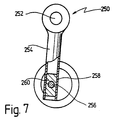
- FIG. 7 An alternative version of the oscillation drive is in Fig. 7 is shown schematically and overall with the number Designated 250.
- An eccentric element 256 is from the motor shaft driven, that with an approximately cylindrical piston 260 is rotatably connected.
- the piston 260 is of one hollow cylindrical guide 258 of a swivel element 254 added, the other end rotatably with the output shaft 252 is connected.
- the motor shaft rotates, the Movement of the eccentric element 256 on the piston 260 on the Transfer pivot member 254 with the piston 260 inside the hollow cylindrical guide 258 is guided and a back and forth executing movement.
- the movement of the Eccentric element 256 via the pivot element 254 in a oscillating rotary movement of the output shaft 252 implemented.
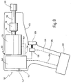
- FIG. 8 Another embodiment of the invention is shown in FIG. 8 represented very schematically and overall with the number Designated 110.
- the drive 112 includes a unidirectional magnet 124 which via a return spring (not shown) against it Direction of rotation is applied.
- the rotary magnet 124 is over control electronics 146, which are described below with reference to FIG. 9 is briefly explained with a rectangular voltage pulse train constant frequency applied.
- the output shaft 114 of the rotary magnet drives one in the manner described above Overrunning clutch 116, via which a tool drive shaft 118 is driven to drive a tool holder 120.
- the switch-off and disconnection device also provided not shown.
- An accumulator 132 is provided for the voltage supply, which is arranged interchangeably on the handle 126 of the housing 122 is.
- the accumulator 132 is connected to the control electronics via lines 134, 136 146 and an ON-OFF switch 130 which can be operated via a button 128.
- the control electronics 146 has a torque setting 144 on that via a collar 142 from outside the housing 122 can be operated.
- the rotary magnet 124 becomes during the duration of a voltage pulse applied to a rotation. During the following The period of time in which there is no voltage becomes the rotary magnet 124 moved back via the return spring until the forward rotation occurs again after the next voltage pulse.
- the achievable performance or the achievable tightening torque of Screwdriver is about the pulse energy by means of a pulse width modulation (PWM) adjustable.
- PWM pulse width modulation
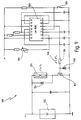
- the voltage pulse sequence which is shown schematically in FIG Number 148 is indicated, can be via the control electronics 146 are generated, for example according to that in FIG. 5 shown circuit is constructed.
- a timer For example, an LM 556 is used, the discharge and Threshold inputs 1 and 2 via an adjustable resistor 144 and there is a series resistor on the positive supply voltage.
- the voltage supplied by output 5 of timer 150 is present a resistor 156, which is connected to ground via a diode 158.
- Switch 152 Via this voltage dropping across the resistor 156 is a Switch 152, which is used, for example, as a field effect transistor (FET) can be trained, controlled.
- the rotary magnet 124 is located between the supply voltage plus and the switch 152 and is bridged by a diode 154.
- the pulse energy can be adjusted by adjusting the Set resistor 144, which changes the pulse width becomes.
Landscapes
- Engineering & Computer Science (AREA)
- Mechanical Engineering (AREA)
- Details Of Spanners, Wrenches, And Screw Drivers And Accessories (AREA)
- Drilling And Boring (AREA)
- Constituent Portions Of Griding Lathes, Driving, Sensing And Control (AREA)
Claims (20)
- Visseuse comportant un dispositif d'entraínement (12, 32, 72, 112 ; 162, 164, 180 ; 272, 274, 276) qui comprend un arbre de sortie (14 ; 34 ; 74 ; 114 ; 180 ; 276) qui exécute un mouvement de rotation intermittent, et qui est accouplé, par un accouplement à roue libre (16 ; 36 ; 76 ; 116 ; 188, 190 ; 278), à un arbre menant d'outil (18 ; 38 ; 78 ; 118 ; 200) pour l'entraínement d'un outil (20 ; 282), caractérisée en ce que sont prévus un dispositif de mise à l'arrêt (96, 98 ; 100 ; 224) pour la mise à l'arrêt du dispositif d'entraínement (72 ; 162, 134, 180) lorsqu'est atteint un couple de rotation donné ainsi qu'un dispositif de séparation (198) pour séparer l'arbre menant d'outil (78 ; 200) du dispositif d'entraínement (72 ; 162, 164, 180), en ce que le dispositif de séparation (198) présente un premier élément d'accouplement (208) lié en rotation à l'arbre menant d'outil (200), lequel élément d'accouplement peut être accouplé au côté sortie d'un accouplement à roue libre (188), ainsi qu'un deuxième élément d'accouplement (212), qui est lié solidairement en rotation avec l'arbre menant d'outil (200), en ce qu'entre le premier élément d'accouplement (208) et le deuxième élément d'accouplement (212) est disposé un élément d'accouplement intermédiaire (210) qui forme avec le deuxième élément d'accouplement (212) un accouplement d'entraínement, par lequel l'élément d'accouplement intermédiaire (210) peut être déplacé, sous charge, en direction du premier élément d'accouplement (208), en ce que l'élément d'accouplement intermédiaire (210) forme avec le premier élément d'accouplement (208) un accouplement de séparation débrayable par coulissement axial de l'élément d'accouplement intermédiaire (210) et en ce que l'élément d'accouplement intermédiaire (210) est sollicité élastiquement en direction du deuxième élément d'accouplement (212).
- Visseuse selon la revendication 1, caractérisée par un dispositif (94 ; 184) pour l'inversion du sens de rotation de l'arbre de sortie (14 ; 34 ; 74 ; 114 ; 200).
- Visseuse selon la revendication 1 ou 2, caractérisée par un dispositif de réglage (98 ; 244) pour le préréglage du couple de coupure.
- Visseuse selon l'une des revendications précédentes, caractérisée en ce que le dispositif d'entraínement comprend un moteur (44 ; 84 ; 162 ; 272), qui est accouplé avec un dispositif d'entraínement en oscillation (49 ; 89 ; 164 ; 250 ; 274), par lequel un mouvement de rotation de l'arbre moteur (48 ; 88 ; 168) est converti en un mouvement de rotation oscillant de l'arbre de sortie (34 ; 74 ; 180 ; 252 ; 276), entraínant l'accouplement à roue libre (36 ; 76 ; 188, 190 ; 278).
- Visseuse selon la revendication 4, caractérisée en ce que le dispositif d'entraínement en oscillation (49 ; 89 ; 164 ; 250) comprend un élément à excentrique (50 ; 170 ; 256), entraíné par l'arbre moteur (48 ; 88 ; 168), par lequel est entraíné un élément pivotant (52 ; 174 ; 254), qui est lié solidairement en rotation avec l'arbre de sortie (34 ; 74 ; 180 ; 252).
- Visseuse selon l'une des revendications précédentes, caractérisée en ce que le dispositif d'entraínement (32 ; 72 ; 162, 164, 180) comporte un moteur électrique (44 ; 84 ; 162 ; 262), un moteur à air comprimé ou un moteur hydraulique.
- Visseuse selon l'une des revendications 1 à 3, caractérisée en ce que le dispositif d'entraínement (112) comprend un aimant rotatif (124), qui est sollicité par une succession d'impulsions de tension destinée à produire le mouvement de rotation intermittent.
- Visseuse selon la revendication 7, caractérisée en ce que l'aimant rotatif (124) est un aimant à un sens de rotation, qui est soumis à une force de rappel dans le sens contraire au sens de rotation.
- Visseuse selon la revendication 7, caractérisée en ce que l'aimant rotatif est un aimant à deux sens de rotation.
- Visseuse selon l'une des revendications 1 à 3, caractérisée en ce que le dispositif d'entraínement comprend un moteur pas à pas, qui reçoit une succession d'impulsions de tension destinée à produire le mouvement de rotation intermittent.
- Visseuse selon l'une des revendications 7 à 10, caractérisée en ce que la fréquence des impulsions et/ou la durée des impulsions sont réglables.
- Visseuse selon l'une des revendications 1 à 11, caractérisée en ce que l'arbre de sortie (180) est maintenu par deux paliers (186, 222) disposés à distance l'un de l'autre, un palier (186) étant fixé dans la direction radiale de l'arbre de sortie (180), tandis que l'autre palier (222) est disposé de manière à pouvoir coulisser dans la direction radiale, à l'encontre d'une précontrainte, et en ce qu'à l'arbre de sortie (180) est associé un élément à capteur (230), afin de mettre à l'arrêt le dispositif d'entraínement (162, 164) lorsque se produit un coulissement radial.
- Visseuse selon la revendication 12, caractérisée en ce qu'un dispositif de réglage (244) est prévu pour produire une précontrainte réglable.
- Visseuse selon la revendication 12 ou 13, caractérisée en ce que l'autre palier (222) est monté dans un guidage glissant (228), qui permet un coulissement dans la direction radiale de l'arbre de sortie (180).
- Visseuse selon l'une des revendications 2 à 14, caractérisée en ce qu'un premier accouplement à roue libre (188) entraínant dans le sens des aiguilles d'une montre et un deuxième accouplement à roue libre (190) entraínant dans le sens contraire aux aiguilles d'une montre, sont disposés l'un à la suite de l'autre dans la direction axiale et en ce qu'il est prévu un élément de commutation (184), pour accoupler au choix soit le premier accouplement à roue libre (188), soit le deuxième (190) avec l'arbre menant d'outil (200).
- Visseuse selon la revendication 15, caractérisée en ce que l'élément de commutation (184) est réalisé en tant que manchon coulissant, qui est monté de manière à pouvoir coulisser dans la direction axiale de l'arbre de sortie (180), en ce que dans une première position avancée en direction de l'arbre menant d'outil (200) du manchon coulissant (184), le premier accouplement à roue libre (188) est accouplé à l'arbre menant d'outil (200) par l'intermédiaire du manchon coulissant (184), et en ce que dans une deuxième position reculée du manchon coulissant (184), le deuxième accouplement à roue libre (190) est accouplé à l'arbre menant d'outil (200).
- Visseuse selon la revendication 16, caractérisée en ce que le manchon coulissant (184) est accouplé dans la première position à l'arbre menant d'outil (200) par l'intermédiaire d'un accouplement à griffes (206), et en ce que dans la deuxième position, il est accouplé à l'arbre menant d'outil (200), par l'intermédiaire d'une fente longitudinale du manchon coulissant (184), dans laquelle s'engage une goupille transversale (194) traversant l'arbre menant d'outil (200).
- Visseuse selon l'une des revendications précédentes, caractérisée en ce que l'accouplement de séparation formé par le premier élément d'accouplement (208) et par l'élément d'accouplement intermédiaire (210) présentent des cames (211) droites avec un flanc d'entraínement s'étendant perpendiculairement à un plan radial, sur l'un (210) des éléments (208, 210), ainsi qu'une came (209) étagée avec une portion droite, dans laquelle le flanc d'entraínement (215) s'étend perpendiculairement à plan radial, et avec une portion oblique, se raccordant à la portion droite, dans laquelle le flanc d'entraínement (216) s'étend obliquement par rapport à un plan radial, sur un autre (208) des éléments (208, 210).
- Visseuse selon l'une des revendications précédentes, caractérisée en ce que le deuxième élément d'accouplement (212) présente une saillie s'étendant dans la direction radiale, qui coopère avec un profil de guidage (213) de l'élément d'accouplement intermédiaire (210), qui s'étend obliquement par rapport à un plan radial.
- Visseuse selon la revendication 19, caractérisée en ce que la saillie s'étendant dans la direction radiale est formée par une goupille transversale (212), qui traverse l'arbre de sortie (200) dans la direction radiale.
Applications Claiming Priority (3)
| Application Number | Priority Date | Filing Date | Title |
|---|---|---|---|
| DE4344849A DE4344849A1 (de) | 1993-12-29 | 1993-12-29 | Werkzeugmaschine |
| DE4344849 | 1993-12-29 | ||
| PCT/EP1994/004281 WO1995017991A2 (fr) | 1993-12-29 | 1994-12-22 | Machine-outil |
Publications (2)
| Publication Number | Publication Date |
|---|---|
| EP0804315A2 EP0804315A2 (fr) | 1997-11-05 |
| EP0804315B1 true EP0804315B1 (fr) | 1999-07-28 |
Family
ID=6506459
Family Applications (1)
| Application Number | Title | Priority Date | Filing Date |
|---|---|---|---|
| EP95904526A Expired - Lifetime EP0804315B1 (fr) | 1993-12-29 | 1994-12-22 | Machine-outil |
Country Status (6)
| Country | Link |
|---|---|
| US (1) | US5868208A (fr) |
| EP (1) | EP0804315B1 (fr) |
| JP (1) | JPH09502134A (fr) |
| AU (1) | AU1317795A (fr) |
| DE (2) | DE4344849A1 (fr) |
| WO (1) | WO1995017991A2 (fr) |
Families Citing this family (68)
| Publication number | Priority date | Publication date | Assignee | Title |
|---|---|---|---|---|
| DE19815443C1 (de) * | 1998-04-07 | 1999-12-23 | Fein C & E | Schleifgerät |
| DE19937767B4 (de) * | 1999-08-10 | 2004-09-09 | Hilti Ag | Handgeführter elektrischer Kombihammer |
| SE520916C2 (sv) * | 1999-12-28 | 2003-09-09 | Atlas Copco Tools Ab | Mutterdragare med momentkoppling med utlösningssensor för kraftavstängning |
| DE10117121A1 (de) * | 2001-04-06 | 2002-10-17 | Bosch Gmbh Robert | Handwerkzeugmaschine |
| US6715380B2 (en) | 2001-05-14 | 2004-04-06 | C. & E. Fein Gmbh & Co. Kg | Power-driven screwdriver |
| DE10124572A1 (de) * | 2001-05-14 | 2002-11-21 | C & E Fein Gmbh & Co Kg | Kraftgetriebener Schrauber mit Drehmomentbegrenzungskupplung |
| SE519658C2 (sv) | 2001-07-06 | 2003-03-25 | Atlas Copco Tools Ab | Metod och mutterdragare med målmomentdetektering genom ljud |
| DE10137896A1 (de) * | 2001-08-02 | 2003-02-20 | Paul-Heinz Wagner | Verfahren zur Steuerung eines intermittierend arbeitenden Schraubwerkzeugs |
| US6758731B2 (en) * | 2001-08-10 | 2004-07-06 | One World Technologies Limited | Orbital sander |
| DE10219755A1 (de) * | 2002-05-02 | 2003-11-13 | Hilti Ag | Überlastschutz für eine drehende Werkzeugmaschine |
| CA2436878C (fr) * | 2002-05-09 | 2011-08-09 | Snap-On Technologies, Inc. | Dispositif automatique de coupure d'air |
| DE10240361A1 (de) * | 2002-09-02 | 2004-03-11 | Hilti Ag | Drehende und schlagende Elektrohandwerkzeugmaschine |
| DE10256547A1 (de) * | 2002-12-04 | 2004-06-24 | Hilti Ag | Mehrteilige Lagerbrücke |
| DE10309012B3 (de) * | 2003-03-01 | 2004-08-12 | Hilti Ag | Steuerverfahren einer axial schlagenden und drehenden Elektrohandwerkzeugmaschine |
| DE10342232A1 (de) * | 2003-09-11 | 2005-04-07 | Robert Bosch Gmbh | Leistungssteuerungsvorrichtung eines Elektrowerkzeugs |
| DE10352500A1 (de) * | 2003-11-11 | 2005-06-09 | Robert Bosch Gmbh | Handwerkzeugmaschine |
| DE10356068A1 (de) * | 2003-12-01 | 2005-06-23 | Robert Bosch Gmbh | Handwerkzeugmaschine |
| DE10358033B4 (de) * | 2003-12-11 | 2007-05-03 | Hilti Ag | Antriebsanordnung |
| US20050130782A1 (en) * | 2003-12-12 | 2005-06-16 | Guenther Boehler Gmbh. | Handheld power tool |
| US6971454B2 (en) * | 2004-03-16 | 2005-12-06 | Bogue Edward M | Pulsed rotation screw removal and insertion device |
| DE102004017946A1 (de) * | 2004-04-14 | 2005-11-03 | Robert Bosch Gmbh | Akkumulatorbetriebene Handwerkzeugmaschine |
| DE102004020177B4 (de) | 2004-04-24 | 2024-07-18 | Robert Bosch Gmbh | Handwerkzeugmaschine mit einem drehenden und/oder schlagenden Antrieb |
| DE102004037072B3 (de) * | 2004-07-30 | 2006-01-12 | Hilti Ag | Handwerkzeuggerät mit Drehimpuls- und Bremskrafterzeuger |
| WO2006020571A2 (fr) * | 2004-08-11 | 2006-02-23 | William Szieff | Outil dote d'indicateurs de mouvement et d'orientation |
| DE102004062858A1 (de) * | 2004-12-21 | 2006-08-10 | C. & E. Fein Gmbh | Verfahren und Vorrichtung zur Herstellung von Bohrungen |
| CN100574946C (zh) * | 2005-06-01 | 2009-12-30 | 密尔沃基电动工具公司 | 动力工具 |
| DE102005057268A1 (de) * | 2005-12-01 | 2007-06-06 | Robert Bosch Gmbh | Handwerkzeugmaschinenumkehreinheit |
| DE102006057283A1 (de) * | 2006-12-05 | 2008-06-12 | Robert Bosch Gmbh | Handwerkzeug |
| US8100745B2 (en) * | 2007-03-16 | 2012-01-24 | Black & Decker Inc. | Low vibration sander with a flexible top handle |
| DE102007018464A1 (de) * | 2007-04-19 | 2008-10-23 | Robert Bosch Gmbh | Motorisch angetriebene Werkzeugmaschine |
| DE102007018466A1 (de) * | 2007-04-19 | 2008-10-23 | Robert Bosch Gmbh | Motorisch angetriebene Werkzeugmaschine |
| EP2722131B1 (fr) | 2007-06-15 | 2016-07-20 | Black & Decker Inc. | Outil d'impact hybride |
| US20090065225A1 (en) * | 2007-09-07 | 2009-03-12 | Black & Decker Inc. | Switchable anti-lock control |
| US7793560B2 (en) * | 2007-09-11 | 2010-09-14 | Black & Decker Inc. | Transmission and variable radially expanding spring clutch assembly |
| US7798245B2 (en) | 2007-11-21 | 2010-09-21 | Black & Decker Inc. | Multi-mode drill with an electronic switching arrangement |
| US7854274B2 (en) * | 2007-11-21 | 2010-12-21 | Black & Decker Inc. | Multi-mode drill and transmission sub-assembly including a gear case cover supporting biasing |
| US7735575B2 (en) | 2007-11-21 | 2010-06-15 | Black & Decker Inc. | Hammer drill with hard hammer support structure |
| US7770660B2 (en) | 2007-11-21 | 2010-08-10 | Black & Decker Inc. | Mid-handle drill construction and assembly process |
| US7717192B2 (en) * | 2007-11-21 | 2010-05-18 | Black & Decker Inc. | Multi-mode drill with mode collar |
| US7717191B2 (en) * | 2007-11-21 | 2010-05-18 | Black & Decker Inc. | Multi-mode hammer drill with shift lock |
| US7762349B2 (en) * | 2007-11-21 | 2010-07-27 | Black & Decker Inc. | Multi-speed drill and transmission with low gear only clutch |
| FR2929981B1 (fr) * | 2008-03-18 | 2012-04-20 | Guy Jacques Perrin | Enrouleur, derouleur motorise portatif pour stores, bannes, volets roulants ou autres. |
| SE532395C2 (sv) * | 2008-05-08 | 2010-01-12 | Atlas Copco Tools Ab | Kraftverktyg för åtdragning av skruvförband samt frikoppling |
| US9193053B2 (en) | 2008-09-25 | 2015-11-24 | Black & Decker Inc. | Hybrid impact tool |
| DE102008050703B3 (de) * | 2008-10-07 | 2009-12-31 | Wacker Neuson Se | Arbeitsgerät mit Überholkupplung |
| JP5333836B2 (ja) * | 2009-03-02 | 2013-11-06 | 日立工機株式会社 | 電動工具および動力工具 |
| US8631880B2 (en) * | 2009-04-30 | 2014-01-21 | Black & Decker Inc. | Power tool with impact mechanism |
| US8540580B2 (en) | 2009-08-12 | 2013-09-24 | Black & Decker Inc. | Tool bit or tool holder for power tool |
| WO2011024697A1 (fr) * | 2009-08-28 | 2011-03-03 | 株式会社マキタ | Outil électrique |
| DE102010031274B4 (de) * | 2009-12-18 | 2023-06-22 | Robert Bosch Gmbh | Handwerkzeugmaschine mit Kühlung des Getriebes |
| US8460153B2 (en) | 2009-12-23 | 2013-06-11 | Black & Decker Inc. | Hybrid impact tool with two-speed transmission |
| US8584770B2 (en) * | 2010-03-23 | 2013-11-19 | Black & Decker Inc. | Spindle bearing arrangement for a power tool |
| DE102010043032A1 (de) * | 2010-10-28 | 2012-05-03 | Hilti Aktiengesellschaft | Steuerungsverfahren für eine Werkzeugmaschine und eine Werkzeugmaschine |
| US9149923B2 (en) | 2010-11-09 | 2015-10-06 | Black & Decker Inc. | Oscillating tools and accessories |
| EP2594364B1 (fr) | 2011-11-15 | 2014-06-04 | C. & E. Fein GmbH | Dispositif d'entraînement oscillant |
| JP2013188812A (ja) * | 2012-03-13 | 2013-09-26 | Hitachi Koki Co Ltd | インパクト工具 |
| US9193055B2 (en) | 2012-04-13 | 2015-11-24 | Black & Decker Inc. | Electronic clutch for power tool |
| US20140182419A1 (en) * | 2012-12-28 | 2014-07-03 | Hsiu-Lin HSU | Motor Accelerator for Automatic Screwdriver |
| JP6085225B2 (ja) * | 2013-06-27 | 2017-02-22 | 株式会社マキタ | ネジ締め電動工具 |
| US10252441B2 (en) | 2013-08-28 | 2019-04-09 | Corning Incorporated | System and method for cutting a wet green ceramic article |
| CN103629505B (zh) * | 2013-12-02 | 2015-10-14 | 宁波汉浦工具有限公司 | 一种手持式电动磨 |
| DE102014202218A1 (de) * | 2014-02-06 | 2015-08-06 | Robert Bosch Gmbh | Handwerkzeugmaschine mit einem elektronisch kommutierten Elektromotor |
| CN107838878A (zh) * | 2016-09-20 | 2018-03-27 | 苏州宝时得电动工具有限公司 | 一种动力工具 |
| CN210307665U (zh) * | 2016-09-30 | 2020-04-14 | 工机控股株式会社 | 电动工具 |
| US11534903B2 (en) * | 2017-08-28 | 2022-12-27 | Apex Brands, Inc. | Power tool two-stage trigger |
| US10875201B2 (en) | 2018-04-04 | 2020-12-29 | Swanstrom Tools Usa Inc. | Relief guard for hand tools |
| CN112031641B (zh) * | 2020-10-09 | 2022-06-28 | 贵州航天天马机电科技有限公司 | 一种锚固钻机用驱动装置 |
| DE102021208359A1 (de) * | 2021-08-02 | 2023-02-02 | Adolf Würth GmbH & Co. KG | Schlag- oder Impulsschrauber und Verfahren zum Eindrehen einer Schraube |
Family Cites Families (31)
| Publication number | Priority date | Publication date | Assignee | Title |
|---|---|---|---|---|
| US1921628A (en) * | 1932-06-06 | 1933-08-08 | Ralph H Maxwell | Portable electric hammer |
| US2392097A (en) * | 1943-08-03 | 1946-01-01 | Chicago Pneumatic Tool Co | Reversible close quarter drill |
| US2764138A (en) * | 1953-03-02 | 1956-09-25 | Atlas Copco Ab | Percussion tools having a reciprocable hammer piston actuated by combustion gases |
| US2825436A (en) * | 1953-07-03 | 1958-03-04 | Chicago Pneumatic Tool Co | Impact clutch |
| DE1483854A1 (de) * | 1966-12-28 | 1970-03-19 | Metabowerke Kg | Bohrhammer |
| DE2039369A1 (de) * | 1969-08-11 | 1971-02-25 | Hitachi Ltd | Antriebsvorrichtung mit Ausnutzung einer elektromagnetischen Vibration |
| US3650336A (en) * | 1970-05-05 | 1972-03-21 | Rockwell Mfg Co | Power driven device |
| DE2229388C3 (de) * | 1972-06-16 | 1981-01-22 | Robert Bosch Gmbh, 7000 Stuttgart | Von Hand zu führender Bohrhammer |
| DE2328826C3 (de) * | 1973-06-06 | 1978-06-08 | Hartmann & Braun Ag, 6000 Frankfurt | Schwingankermotor |
| US4019589A (en) * | 1975-12-02 | 1977-04-26 | Chicago Pneumatic Tool Company | Pulse motor nut runner |
| DE8102453U1 (de) * | 1981-01-31 | 1982-09-09 | Kress-elektrik GmbH & Co, Elektromotorenfabrik, 7457 Bisingen | Elektrohandwerkzeugmaschine zum Schrauben, Bohren und eventuell Schlagbohren |
| DE3329010A1 (de) * | 1983-08-11 | 1985-02-28 | Robert Bosch Gmbh, 7000 Stuttgart | Bohrhammer |
| US4591299A (en) * | 1984-05-21 | 1986-05-27 | Dresser Industries, Inc. | Rapid feed apparatus for automatic feed drills or the like |
| DE3443670A1 (de) * | 1984-11-30 | 1986-06-05 | C. & E. Fein Gmbh & Co, 7000 Stuttgart | Kraftgetriebene schraubvorrichtung mit variabler drehmomenteinstellung |
| DE3621182A1 (de) * | 1986-06-25 | 1988-01-07 | Bosch Gmbh Robert | Handwerkzeugmaschine, insbesondere bohr- und/oder schlaghammer |
| US4850955A (en) * | 1986-12-02 | 1989-07-25 | Codman & Shurtleff | Body fluid transfer device |
| DE3710149C1 (de) * | 1987-03-27 | 1988-08-18 | Spinner Gmbh Elektrotech | Schalterantrieb fuer einen Drehschalter |
| DE3740083C2 (de) * | 1987-11-26 | 1995-01-12 | Hans Hohmann | Hydraulischer Kraftschrauber |
| US4799833A (en) * | 1987-12-14 | 1989-01-24 | Dresser Industries, Inc. | Clutch for positive feed drill |
| DE3742952A1 (de) * | 1987-12-18 | 1989-07-06 | Fein C & E | Maschine mit variabler drehmomenteinstellung |
| DE3840974A1 (de) * | 1988-12-06 | 1990-06-07 | Fein C & E | Oszillationsantrieb |
| DE8904356U1 (de) * | 1989-04-07 | 1989-06-15 | Licentia Patent-Verwaltungs-Gmbh, 6000 Frankfurt | Elektromotorisch angetriebener Handschrauber |
| DE3931329C1 (fr) * | 1989-05-31 | 1990-06-28 | Robert Bosch Gmbh, 7000 Stuttgart, De | |
| DE3940743A1 (de) * | 1989-12-09 | 1991-06-13 | Chicago Pneumatic Tool Gmbh | Lochkreissaege |
| JPH0777687B2 (ja) * | 1990-01-26 | 1995-08-23 | 日東工器株式会社 | ドリル装置 |
| DE4100185A1 (de) * | 1991-01-05 | 1992-07-09 | Bosch Gmbh Robert | Handwerkzeugmaschine mit sicherheitskupplung |
| DE4123349C1 (de) * | 1991-07-15 | 1993-03-04 | Fein C & E | Schrauber mit variabler Drehmomenteinstellung |
| JP2961995B2 (ja) * | 1991-10-08 | 1999-10-12 | 味の素株式会社 | ピペリジン誘導体およびこれを含有する抗不整脈薬 |
| JPH05268643A (ja) * | 1992-03-24 | 1993-10-15 | Meisei Electric Co Ltd | 電話装置における停電検出方式 |
| DE4213421C2 (de) * | 1992-04-23 | 1998-08-27 | Fraunhofer Ges Forschung | Verwendung eines automatischen Taumelnietwerkzeugs mit einem Industrieroboter |
| US5346023A (en) * | 1993-02-11 | 1994-09-13 | Hitachi Koki Company Limited | Slipping torque changing apparatus for impact tool |
-
1993
- 1993-12-29 DE DE4344849A patent/DE4344849A1/de not_active Ceased
-
1994
- 1994-12-22 EP EP95904526A patent/EP0804315B1/fr not_active Expired - Lifetime
- 1994-12-22 DE DE59408554T patent/DE59408554D1/de not_active Expired - Lifetime
- 1994-12-22 WO PCT/EP1994/004281 patent/WO1995017991A2/fr active IP Right Grant
- 1994-12-22 AU AU13177/95A patent/AU1317795A/en not_active Abandoned
- 1994-12-22 JP JP7517773A patent/JPH09502134A/ja active Pending
-
1996
- 1996-06-28 US US08/671,688 patent/US5868208A/en not_active Expired - Fee Related
Also Published As
| Publication number | Publication date |
|---|---|
| AU1317795A (en) | 1995-07-17 |
| US5868208A (en) | 1999-02-09 |
| DE59408554D1 (de) | 1999-09-02 |
| JPH09502134A (ja) | 1997-03-04 |
| WO1995017991A2 (fr) | 1995-07-06 |
| EP0804315A2 (fr) | 1997-11-05 |
| WO1995017991A3 (fr) | 1995-09-21 |
| DE4344849A1 (de) | 1995-07-06 |
Similar Documents
| Publication | Publication Date | Title |
|---|---|---|
| EP0804315B1 (fr) | Machine-outil | |
| DE69400262T2 (de) | Motorgetriebenes Gerät und Mechanismus dafür | |
| DE3918227C1 (fr) | ||
| EP2140976B1 (fr) | Vis autotaraudeuse à frapper | |
| DE69614974T2 (de) | Drehbohrhammer | |
| DE4236819C2 (de) | Motorisch angetriebene Drehwerkzeugeinrichtung | |
| EP0523477B1 (fr) | Outil de vissage avec réglage du couple variable | |
| DE69228634T2 (de) | Getriebe eines elektrisch angetriebenen Werkzeuges | |
| EP0670199B1 (fr) | Appareil pour la pose des écrous à rivets aveugles | |
| DE2825022C2 (fr) | ||
| EP0329852B1 (fr) | Clé à écrous à moteur | |
| EP2599568B1 (fr) | Dispositif de forage | |
| EP0990488B1 (fr) | Tournevis motorisé | |
| DE4301610C2 (de) | Schlagschrauber | |
| DE19705378A1 (de) | Kupplungsmechanismus zur Verwendung in einem energiebetriebenen Werkzeug | |
| DE4328599C2 (de) | Rotations-Schlagwerkzeug | |
| EP0755754B1 (fr) | Dispositif de vissage | |
| DE3235544C2 (fr) | ||
| DE3904085C2 (fr) | ||
| EP2140978B1 (fr) | Vis autotaraudeuse à frapper | |
| DE3015423A1 (de) | Motorisch beschriebener abschaltschrauber | |
| DE2557118C2 (de) | Tragbare Drehschlag-Maschinen mit ausrastbarem Schlagwerk | |
| DE3431630C2 (de) | Elektrowerkzeug zum wahlweisen Bohren oder Schrauben | |
| EP0239670A2 (fr) | Machine motorisée avec réglage du couple, en particulier outillages électriques | |
| DE4305967C2 (de) | Schaltvorrichtung zur Spindelarretierung für Elektrowerkzeuge |
Legal Events
| Date | Code | Title | Description |
|---|---|---|---|
| PUAI | Public reference made under article 153(3) epc to a published international application that has entered the european phase |
Free format text: ORIGINAL CODE: 0009012 |
|
| 17P | Request for examination filed |
Effective date: 19960626 |
|
| AK | Designated contracting states |
Kind code of ref document: A2 Designated state(s): CH DE FR GB IT LI |
|
| 17Q | First examination report despatched |
Effective date: 19971209 |
|
| GRAG | Despatch of communication of intention to grant |
Free format text: ORIGINAL CODE: EPIDOS AGRA |
|
| GRAG | Despatch of communication of intention to grant |
Free format text: ORIGINAL CODE: EPIDOS AGRA |
|
| GRAH | Despatch of communication of intention to grant a patent |
Free format text: ORIGINAL CODE: EPIDOS IGRA |
|
| GRAH | Despatch of communication of intention to grant a patent |
Free format text: ORIGINAL CODE: EPIDOS IGRA |
|
| GRAA | (expected) grant |
Free format text: ORIGINAL CODE: 0009210 |
|
| AK | Designated contracting states |
Kind code of ref document: B1 Designated state(s): CH DE FR GB IT LI |
|
| PG25 | Lapsed in a contracting state [announced via postgrant information from national office to epo] |
Ref country code: IT Free format text: LAPSE BECAUSE OF FAILURE TO SUBMIT A TRANSLATION OF THE DESCRIPTION OR TO PAY THE FEE WITHIN THE PRE;WARNING: LAPSES OF ITALIAN PATENTS WITH EFFECTIVE DATE BEFORE 2007 MAY HAVE OCCURRED AT ANY TIME BEFORE 2007. THE CORRECT EFFECTIVE DATE MAY BE DIFFERENT FROM THE ONE RECORDED.SCRIBED TIME-LIMIT Effective date: 19990728 Ref country code: GB Free format text: LAPSE BECAUSE OF FAILURE TO SUBMIT A TRANSLATION OF THE DESCRIPTION OR TO PAY THE FEE WITHIN THE PRESCRIBED TIME-LIMIT Effective date: 19990728 Ref country code: FR Free format text: LAPSE BECAUSE OF FAILURE TO SUBMIT A TRANSLATION OF THE DESCRIPTION OR TO PAY THE FEE WITHIN THE PRESCRIBED TIME-LIMIT Effective date: 19990728 |
|
| REG | Reference to a national code |
Ref country code: CH Ref legal event code: EP |
|
| REG | Reference to a national code |
Ref country code: CH Ref legal event code: NV Representative=s name: TROESCH SCHEIDEGGER WERNER AG |
|
| REF | Corresponds to: |
Ref document number: 59408554 Country of ref document: DE Date of ref document: 19990902 |
|
| EN | Fr: translation not filed | ||
| GBV | Gb: ep patent (uk) treated as always having been void in accordance with gb section 77(7)/1977 [no translation filed] |
Effective date: 19990728 |
|
| PLBE | No opposition filed within time limit |
Free format text: ORIGINAL CODE: 0009261 |
|
| STAA | Information on the status of an ep patent application or granted ep patent |
Free format text: STATUS: NO OPPOSITION FILED WITHIN TIME LIMIT |
|
| 26N | No opposition filed | ||
| PGFP | Annual fee paid to national office [announced via postgrant information from national office to epo] |
Ref country code: CH Payment date: 20011120 Year of fee payment: 8 |
|
| PG25 | Lapsed in a contracting state [announced via postgrant information from national office to epo] |
Ref country code: LI Free format text: LAPSE BECAUSE OF NON-PAYMENT OF DUE FEES Effective date: 20021231 Ref country code: CH Free format text: LAPSE BECAUSE OF NON-PAYMENT OF DUE FEES Effective date: 20021231 |
|
| REG | Reference to a national code |
Ref country code: CH Ref legal event code: PL |
|
| PGFP | Annual fee paid to national office [announced via postgrant information from national office to epo] |
Ref country code: DE Payment date: 20121219 Year of fee payment: 19 |
|
| REG | Reference to a national code |
Ref country code: DE Ref legal event code: R119 Ref document number: 59408554 Country of ref document: DE |
|
| REG | Reference to a national code |
Ref country code: DE Ref legal event code: R119 Ref document number: 59408554 Country of ref document: DE Effective date: 20140701 |
|
| PG25 | Lapsed in a contracting state [announced via postgrant information from national office to epo] |
Ref country code: DE Free format text: LAPSE BECAUSE OF NON-PAYMENT OF DUE FEES Effective date: 20140701 |