EP0804315B1 - Machine-tool - Google Patents
Machine-tool Download PDFInfo
- Publication number
- EP0804315B1 EP0804315B1 EP95904526A EP95904526A EP0804315B1 EP 0804315 B1 EP0804315 B1 EP 0804315B1 EP 95904526 A EP95904526 A EP 95904526A EP 95904526 A EP95904526 A EP 95904526A EP 0804315 B1 EP0804315 B1 EP 0804315B1
- Authority
- EP
- European Patent Office
- Prior art keywords
- coupling element
- screw driver
- driver according
- output shaft
- tool
- Prior art date
- Legal status (The legal status is an assumption and is not a legal conclusion. Google has not performed a legal analysis and makes no representation as to the accuracy of the status listed.)
- Expired - Lifetime
Links
Images


Classifications
-
- B—PERFORMING OPERATIONS; TRANSPORTING
- B23—MACHINE TOOLS; METAL-WORKING NOT OTHERWISE PROVIDED FOR
- B23D—PLANING; SLOTTING; SHEARING; BROACHING; SAWING; FILING; SCRAPING; LIKE OPERATIONS FOR WORKING METAL BY REMOVING MATERIAL, NOT OTHERWISE PROVIDED FOR
- B23D29/00—Hand-held metal-shearing or metal-cutting devices
- B23D29/005—Hand-held metal-shearing or metal-cutting devices for cutting sheets
-
- B—PERFORMING OPERATIONS; TRANSPORTING
- B23—MACHINE TOOLS; METAL-WORKING NOT OTHERWISE PROVIDED FOR
- B23D—PLANING; SLOTTING; SHEARING; BROACHING; SAWING; FILING; SCRAPING; LIKE OPERATIONS FOR WORKING METAL BY REMOVING MATERIAL, NOT OTHERWISE PROVIDED FOR
- B23D47/00—Sawing machines or sawing devices working with circular saw blades, characterised only by constructional features of particular parts
- B23D47/12—Sawing machines or sawing devices working with circular saw blades, characterised only by constructional features of particular parts of drives for circular saw blades
-
- B—PERFORMING OPERATIONS; TRANSPORTING
- B23—MACHINE TOOLS; METAL-WORKING NOT OTHERWISE PROVIDED FOR
- B23Q—DETAILS, COMPONENTS, OR ACCESSORIES FOR MACHINE TOOLS, e.g. ARRANGEMENTS FOR COPYING OR CONTROLLING; MACHINE TOOLS IN GENERAL CHARACTERISED BY THE CONSTRUCTION OF PARTICULAR DETAILS OR COMPONENTS; COMBINATIONS OR ASSOCIATIONS OF METAL-WORKING MACHINES, NOT DIRECTED TO A PARTICULAR RESULT
- B23Q11/00—Accessories fitted to machine tools for keeping tools or parts of the machine in good working condition or for cooling work; Safety devices specially combined with or arranged in, or specially adapted for use in connection with, machine tools
- B23Q11/04—Arrangements preventing overload of tools, e.g. restricting load
-
- B—PERFORMING OPERATIONS; TRANSPORTING
- B23—MACHINE TOOLS; METAL-WORKING NOT OTHERWISE PROVIDED FOR
- B23Q—DETAILS, COMPONENTS, OR ACCESSORIES FOR MACHINE TOOLS, e.g. ARRANGEMENTS FOR COPYING OR CONTROLLING; MACHINE TOOLS IN GENERAL CHARACTERISED BY THE CONSTRUCTION OF PARTICULAR DETAILS OR COMPONENTS; COMBINATIONS OR ASSOCIATIONS OF METAL-WORKING MACHINES, NOT DIRECTED TO A PARTICULAR RESULT
- B23Q5/00—Driving or feeding mechanisms; Control arrangements therefor
- B23Q5/02—Driving main working members
- B23Q5/04—Driving main working members rotary shafts, e.g. working-spindles
-
- B—PERFORMING OPERATIONS; TRANSPORTING
- B24—GRINDING; POLISHING
- B24B—MACHINES, DEVICES, OR PROCESSES FOR GRINDING OR POLISHING; DRESSING OR CONDITIONING OF ABRADING SURFACES; FEEDING OF GRINDING, POLISHING, OR LAPPING AGENTS
- B24B47/00—Drives or gearings; Equipment therefor
- B24B47/10—Drives or gearings; Equipment therefor for rotating or reciprocating working-spindles carrying grinding wheels or workpieces
-
- B—PERFORMING OPERATIONS; TRANSPORTING
- B25—HAND TOOLS; PORTABLE POWER-DRIVEN TOOLS; MANIPULATORS
- B25B—TOOLS OR BENCH DEVICES NOT OTHERWISE PROVIDED FOR, FOR FASTENING, CONNECTING, DISENGAGING OR HOLDING
- B25B21/00—Portable power-driven screw or nut setting or loosening tools; Attachments for drilling apparatus serving the same purpose
- B25B21/02—Portable power-driven screw or nut setting or loosening tools; Attachments for drilling apparatus serving the same purpose with means for imparting impact to screwdriver blade or nut socket
Definitions
- the invention relates to a machine tool in the form of a Screwdriver with a drive comprising an output shaft, which performs an intermittent rotational movement, and which over a one-way clutch with a tool drive shaft for driving a tool is coupled.
- Such a machine tool can be used as a screwdriver known from US-A-2 392 097.
- the aforementioned machine tool enables transmission a relatively large torque on the tool, does not allow precise shutdown of the drive Reaching a predetermined torque.
- the invention is therefore based on the object, a To create screwdrivers that can be used with the high tool torque with a relatively low one
- Has reaction torque and a shutdown as precise as possible of the screwdriver when a predetermined torque is reached enables.
- a shutdown device to switch off the drive when a predetermined torque and a separating device for separating the tool drive shaft are provided by the drive that the Separating device rotatable with the tool drive shaft connected connected first coupling element which with the Output side of a one-way clutch can be coupled, and a has a second coupling element which is non-rotatable with the tool drive shaft is connected between the first coupling element and the second coupling element, an intermediate coupling element is arranged with the second coupling element forms a driving clutch over which the intermediate coupling element under load towards the first coupling element is displaceable that the intermediate coupling element with the first Coupling element with axial displacement of the intermediate coupling element disengageable separating clutch forms, and that the intermediate coupling element in the direction of the second Coupling element is spring loaded.
- the object of the invention is completely achieved in this way, because high torque with relatively low drive power can be achieved because the reaction moment due to the novel Drive is kept relatively low and by the structure the switch-off device and the separating device for separating the tool drive shaft a very precise adherence to a can reach the specified tightening torque.
- a screwdriver according to the invention is particularly notable characterized in that the tightening torque is in a wide range can be preset very precisely, provided a corresponding one Torque shutdown is provided.
- reaction torque compared to conventional screwdrivers significantly reduced with shutdown device. Be at the same time screws or nuts to be tightened or loosened considerably less stressed than when working with conventional pulse or Impact wrenches.
- an actuator for presetting the Shutdown torque may be provided.
- the intermittent rotary movement of the drive shaft can basically be generated in different ways.
- the rotary movement of a drive motor via an oscillation drive into an oscillating rotary movement be implemented.
- a rotary magnet or a Stepper motor are used, the corresponding one Voltage pulse train is driven.
- the drive of the machine tool comprises a motor coupled to an oscillation drive is a rotary motion of the motor shaft into an oscillating Rotational movement of the one-way clutch driving Output shaft is implemented.
- oscillation drives are basically known and can be used advantageously for this version.
- the machine tool according to the invention has the advantage that due to the oscillating around a fixed swivel axis Rotary movement of the output shaft of the oscillation drive practically reaction-free work results because of every rotary movement the output shaft of the oscillation drive in the direction of rotation the tool has an equally long rotational movement in opposite directions Direction follows.
- the amplitude of the oscillation movement can fixed axis of rotation adapted to the respective application become.
- the frequency of the oscillation drive can be changed be carried out to regulate the performance of the tool.
- the oscillation drive can basically be different Species.
- the oscillation drive comprises an eccentric element driven by the motor shaft, from which a pivoting element is driven, which is connected to the output shaft is rotatably connected.
- An electric motor a compressed air motor, a hydraulic motor or the like may be provided.
- Another way of generating an intermittent Rotary movement of the output shaft consists in the use of a Rotary magnet that generates a voltage pulse train the intermittent rotary movement is applied.
- This measure has the advantage that it is particularly simple Design results, since only a rotary magnet is required, of the corresponding control electronics with a voltage pulse train is acted upon.
- a device rotating magnet can be used as the rotating magnet are provided that this with a restoring force against the Direction of rotation is applied, which generates about a spring can be.
- the rotating magnet can also be used as a bidirectional rotating magnet be formed, if provided on a return spring should be dispensed with.
- the electronic Control generate a corresponding reset pulse.
- Control of performance can be done in a simple manner be achieved that the pulse energy of the voltage pulse train with constant frequency by means of pulse width modulation (PWM) is adjustable.
- PWM pulse width modulation
- the torque transferred to the tool depends on the pulse energy.
- the Pulse frequency can be changed to the performance of the tool to control.
- the frequency can only be used to a certain extent Frame can be changed because of the mechanically vibrating system on the one hand could be brought into resonance or on the other hand if the frequency is too high, the rotating magnet stops the result could be.
- the output shaft taken up by two spaced apart bearings, wherein the one bearing fixed in the radial direction of the output shaft is, while the other bearing against radial preload is arranged displaceably, the output shaft a sensor element is assigned to the drive when it occurs switch off a radial displacement.
- an actuator for generating an adjustable Preload is provided to adjust the tripping torque to enable.
- the other bearing can be taken up by a sliding guide be a displacement in the radial direction of the output shaft allowed.
- a first one-way clutch and clockwise a second one-way clutch that moves counterclockwise Arranged one behind the other in the axial direction, with a switching element is provided to choose either either the first or the second one-way clutch with the tool drive shaft couple.
- the switching element designed as a sliding sleeve in the axial direction of the output shaft is slidably mounted, in a first in Direction on the tool drive shaft advanced position the sliding sleeve, the first one-way clutch over the sliding sleeve is coupled to the tool drive shaft, and wherein in a second retracted position of the sliding sleeve the second Overrunning clutch is coupled to the tool drive shaft.
- the first coupling element and the intermediate coupling element formed coupling straight cam with a vertical to the driving flank on a radial plane the elements on, as well as offset cams with a straight Section in which the driving flank is perpendicular to a Radial plane extends, and with an oblique, to the straight section adjoining section in which the Driving flank extends obliquely to a radial plane on one of the other elements.
- This cam shape is used when the machine tool starts up engagement of the clutch is ensured. This should the slope of the sloping portions of the offset cams be dimensioned so that first the intermediate coupling element with its straight cams between the straight cam sections of the first coupling element engages before the intermediate coupling element under the effect of the transmitted torque is moved towards the second coupling element.
- the second Coupling element extending in a radial direction Projection on that with a guide curve of the intermediate coupling element, that extends obliquely to a radial plane, cooperates.
- This measure has the advantage of being particularly simple and Construction of the driving clutch that can be manufactured cost-effectively.
- the Radially extending projection by a cross pin be formed, which passes through the output shaft in the radial direction.
- the driving clutch can be particularly simple Way by a cross pin fixable in a radial bore in connection with an arranged obliquely to a radial plane Realize leadership curve.
- the slope of the guide curve should greater than the inclination of the oblique cam sections of the Intermediate clutch element to engage the separating clutch ensure at the beginning.
- Fig. 1 is a machine tool according to the invention, the used as a screwdriver, extremely schematic shown and designated overall by the number 160.
- the machine tool 160 includes an electric motor 162, an output shaft 180 via an oscillation drive 164 drives.
- the drive shaft 180 is either via a first one-way clutch 188, which drives clockwise, or via a second one-way clutch 190, which is counterclockwise entrains, connectable to a tool drive shaft 200 to a inserted into a tool holder 202 of the tool drive shaft 200 Power tool.
- a first one-way clutch 188 which drives clockwise
- a second one-way clutch 190 which is counterclockwise entrains, connectable to a tool drive shaft 200 to a inserted into a tool holder 202 of the tool drive shaft 200 Power tool.
- To switch between the first one-way clutch 188 and the second one-way clutch 190 So to switch between clockwise and counterclockwise rotation, is used switching element designated overall by the number 184.
- the oscillation drive 164 comprises according to FIGS. 1 and 4 on the motor shaft 168, which protrude from the motor housing End on a flanged holder 166 by means of a Bearing 181 is mounted, arranged eccentric element 170 Eccentric element 170 is enclosed by a needle sleeve 172 which serves as a pivot bearing.
- On the output shaft 180 is a swivel element 174 non-rotatably arranged, in the direction of the motor shaft 168 protruding section through a U-shaped cutout two swivel arms 176 are formed, between which the Needle sleeve 172 is enclosed from both sides.
- the switching element 184 is designed as a cylindrical switching sleeve, which is axially displaceably mounted on the output shaft 180 is.
- the switching sleeve 184 are the first one after the other One-way clutch 188, a bearing 186 and the second one-way clutch 190 arranged.
- the switching sleeve 184 is with the bearing 186 axially displaceable on the output shaft 180 and with a second bearing 196, which at its front, the tool holder 202 facing end is provided on the tool drive shaft 200 slidable in the axial direction.
- Fig. 1 In the position shown in Fig. 1 is the Switch sleeve 184 in a first, in the direction of the tool holder 202 advanced position in which its the tool holder 202 facing end face with radial Cam 205 is provided, between cam 207 (Fig. 3a, b) one first coupling element 208 of a subsequent overall engages with the separator designated by number 198, with which they form a dog clutch 206.
- the torque is therefore in the position shown in FIG. 1 from the output shaft 180 via the first one-way clutch 188 transferred to the shift sleeve 184, from which the drive torque via the dog clutch 206 and the separator 198 is transmitted to the tool drive shaft 200.
- the second one-way clutch 190 is inoperative.
- the tool drive shaft 200 has a smaller diameter than the output shaft 180 and is on the output shaft 180 facing end against this by means of a thrust bearing stored, which is indicated by the number 192 and in simplest case is designed as a ball, in corresponding Recesses of the output shaft 180 and the tool drive shaft 200 is held.
- the tool drive shaft 200 is on its Output shaft 180 facing end further from a cross pin 194 penetrates, the two ends of which laterally radially from the tool drive shaft 200 protrude.
- a cross pin 194 penetrates, the two ends of which laterally radially from the tool drive shaft 200 protrude.
- the ends of cross pin 194 freely within the second one-way clutch 190 rotate so that it is complete has no function. If, on the other hand, the sliding sleeve 184 to the right in the direction of the oscillation drive 164 in the pushed back position shown in FIG this cross pin 194 in a longitudinal slot 197, which is between the second bearing 196 and the second one-way clutch 190 extends. This creates a positive connection between the switching sleeve 184 and the tool drive shaft 200 in the position shown in FIG.
- the separating device 198 consists of the first coupling element 208, from an intermediate coupling element 210 and from a second Coupling element 212. There is between the first coupling element 208 and the intermediate coupling element 210 a spring element 214 arranged, which is designed as a coil spring and that Intermediate coupling element 210 against the second coupling element 212 presses.
- the first clutch element 208 is a clutch disc trained and rotatable, but not in the axial direction slidably arranged on the tool drive shaft 200.
- the first coupling element 208 has the radially extending side facing the switching sleeve 184 Cam body 207 to match the corresponding cam bodies 205 a claw coupling on the end face of the switching sleeve 184 206 to form the in the clockwise position shown in Fig. 6 a transmission of the torque from the shift sleeve 184 ensures on the first coupling element 208.
- first coupling element 208 On the side of the intermediate coupling element 210 first coupling element 208 are stepped cam bodies 209 provided a straight, extending from the face have extending portion in which the driving flank 215 extends perpendicular to a radial plane to which a sloping section follows, in which the driving flank 216 runs obliquely to a radial plane.
- This weird Section of each cam 209 runs on the end face 217 of the cam, which extends parallel to a radial plane.
- the intermediate coupling element 210 has the first on it Coupling element 208 facing side straight cam 211, which extend in the radial direction.
- the second coupling element 212 is designed as a cross pin, which radially penetrates the tool drive shaft 200 and protrudes from it with both ends.
- the intermediate coupling element 210 which is freely rotatable and axially displaceable the tool drive shaft 200 is arranged on it the second coupling element 212 in its side Shell surface two V-shaped, offset by 180 ° to each other Recesses on, each sloping guide curves 213 for form the cross pin 212 on which it can slide.
- the separator 198 functions as follows.
- the first step is the spring element 214 is compressed by the contact pressure and the intermediate coupling element 210 against by the spring pressure the second coupling element 212 pressed so that the cross pin at the end of the intermediate coupling element 212 Guide slope 213 is present, so that the drawn in Fig. 3a Position results.
- the straight cams 211 move due to the transmitted torque of the intermediate coupling element 210 first between the straight ones Driving flanks 215 of the cams 209 of the first coupling element 208 so that the clutch is engaged and that Torque is transmitted positively.
- the intermediate coupling element 210 its guide curves 213 against the spring force along the two Ends of the cross pin 212 so that the top half from Fig. 3b results position.
- FIG. 5 A slightly modified from the embodiment of FIG. 1 Machine tool is shown in Fig. 5 and overall with number 220.
- the machine tool has a long design 220 in contrast to a short design of the machine tool 160 in FIG. 1, in which the electric motor 162 parallel to Output shaft 180 is arranged such that the sliding sleeve 184 is arranged approximately parallel to the electric motor 162 or is movable.
- FIG. 5 is the sliding sleeve 184 opposite end of the output shaft 180 a shutdown device 224 for switching off the electric motor when reached a pre-set torque.
- Your structure corresponds completely to the structure of those indicated in FIG. 1 Shutdown device 224.
- the shutdown device 224 has a holder according to FIG. 5 226, which is flanged to the electric motor 162 and in the output shaft 180 on the tool drive shaft 200 opposite end is supported with a bearing 222.
- the other end of the output shaft 180 is on the shift sleeve 184 by means of the bearing 186 in the previously based on FIG. 1 described manner stored, which in turn with their second Bearing 196 mounted on the tool drive shaft 200 and axially is slidable to this. That of the tool drive shaft 200 facing end of the output shaft 180 is thus over the Switching sleeve 184 by means of the bearing 186 and the bearing 196 in Radial direction fixed, the tool drive shaft 200th at its other end in turn with the bearing 204 on the machine housing 203 is stored.
- the other bearing 222 of the output shaft 180 is as detailed 6 can be seen in the radial direction by means of a Slideway 228 slidably mounted by a certain amount.
- the other bearing 222 is via an actuator 244 biased in the radial direction by means of a spring 232, see above that it is acted against a sensor element 230, which on on the opposite side of the slide guide 228 is.
- the sensor element 230 receives a signal, causing the shutdown of the electric motor.
- the sensor element is expedient 230 also designed as a switch for the electric motor 162.
- Allowing 180 acting prestress is an overall provided with the number 244, which has an adjusting element 240 which acts as a threaded plug is formed, which in a thread 238 of the holder 226 a collar 242 is adjustable from the outside.
- the other Bearing 222 is via a pin 234 by means of the force of the Spring element 232 is applied between a collar 236th of pin 234 and end face 246 of the adjustment element 240 is included.
- Pin 234 is on the output shaft thereof 180 opposite end in a central hole 248 of the adjusting element 240 slidably received.
- the bias of the Spring element 232 increases, so that a shutdown of the electric motor 162 only occurs at a higher switch-off torque.
- the threaded plug is further screwed out of the thread 238, the preload of the spring element 232, preferably as a coil spring surrounding pin 234 is formed, so that there is a lower switch-off torque results.
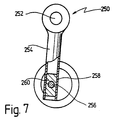
- FIG. 7 An alternative version of the oscillation drive is in Fig. 7 is shown schematically and overall with the number Designated 250.
- An eccentric element 256 is from the motor shaft driven, that with an approximately cylindrical piston 260 is rotatably connected.
- the piston 260 is of one hollow cylindrical guide 258 of a swivel element 254 added, the other end rotatably with the output shaft 252 is connected.
- the motor shaft rotates, the Movement of the eccentric element 256 on the piston 260 on the Transfer pivot member 254 with the piston 260 inside the hollow cylindrical guide 258 is guided and a back and forth executing movement.
- the movement of the Eccentric element 256 via the pivot element 254 in a oscillating rotary movement of the output shaft 252 implemented.
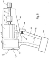
- FIG. 8 Another embodiment of the invention is shown in FIG. 8 represented very schematically and overall with the number Designated 110.
- the drive 112 includes a unidirectional magnet 124 which via a return spring (not shown) against it Direction of rotation is applied.
- the rotary magnet 124 is over control electronics 146, which are described below with reference to FIG. 9 is briefly explained with a rectangular voltage pulse train constant frequency applied.
- the output shaft 114 of the rotary magnet drives one in the manner described above Overrunning clutch 116, via which a tool drive shaft 118 is driven to drive a tool holder 120.
- the switch-off and disconnection device also provided not shown.
- An accumulator 132 is provided for the voltage supply, which is arranged interchangeably on the handle 126 of the housing 122 is.
- the accumulator 132 is connected to the control electronics via lines 134, 136 146 and an ON-OFF switch 130 which can be operated via a button 128.
- the control electronics 146 has a torque setting 144 on that via a collar 142 from outside the housing 122 can be operated.
- the rotary magnet 124 becomes during the duration of a voltage pulse applied to a rotation. During the following The period of time in which there is no voltage becomes the rotary magnet 124 moved back via the return spring until the forward rotation occurs again after the next voltage pulse.
- the achievable performance or the achievable tightening torque of Screwdriver is about the pulse energy by means of a pulse width modulation (PWM) adjustable.
- PWM pulse width modulation
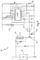
- the voltage pulse sequence which is shown schematically in FIG Number 148 is indicated, can be via the control electronics 146 are generated, for example according to that in FIG. 5 shown circuit is constructed.
- a timer For example, an LM 556 is used, the discharge and Threshold inputs 1 and 2 via an adjustable resistor 144 and there is a series resistor on the positive supply voltage.
- the voltage supplied by output 5 of timer 150 is present a resistor 156, which is connected to ground via a diode 158.
- Switch 152 Via this voltage dropping across the resistor 156 is a Switch 152, which is used, for example, as a field effect transistor (FET) can be trained, controlled.
- the rotary magnet 124 is located between the supply voltage plus and the switch 152 and is bridged by a diode 154.
- the pulse energy can be adjusted by adjusting the Set resistor 144, which changes the pulse width becomes.
Landscapes
- Engineering & Computer Science (AREA)
- Mechanical Engineering (AREA)
- Details Of Spanners, Wrenches, And Screw Drivers And Accessories (AREA)
- Drilling And Boring (AREA)
- Constituent Portions Of Griding Lathes, Driving, Sensing And Control (AREA)
Description
Die Erfindung betrifft eine Werkzeugmaschine in Form eines Schraubers mit einem Antrieb, der eine Abtriebswelle umfaßt, die eine intermittierende Drehbewegung ausführt, und die über eine Freilaufkupplung mit einer Werkzeugantriebswelle zum Antrieb eines Werkzeuges gekoppelt ist.The invention relates to a machine tool in the form of a Screwdriver with a drive comprising an output shaft, which performs an intermittent rotational movement, and which over a one-way clutch with a tool drive shaft for driving a tool is coupled.
Eine derartige als Schrauber verwendbare Werkzeugmaschine ist aus der US-A-2 392 097 bekannt. Such a machine tool can be used as a screwdriver known from US-A-2 392 097.
Bei dem bekannten Schrauber wird die Drehbewegung eines Elektromotors in eine um eine feste Drehachse hin- und heroszillierende Drehbewegung umgesetzt, die dann wiederum über einen Ratschentrieb, der nur in einer Drehrichtung mitnimmt, in eine intermittierende Drehbewegung einer Werkzeugantriebswelle zum Antrieb eines Werkzeugs umgesetzt wird.In the known screwdriver, the rotary movement of an electric motor in a oscillating around a fixed axis of rotation Rotational movement implemented, which in turn via a ratchet drive, which only moves in one direction of rotation, in an intermittent one Rotary movement of a tool drive shaft for driving of a tool is implemented.
Grundsätzlich besteht bei Werkzeugmaschinen, die als Schrauber oder Bohrer eingesetzt werden, das Problem, ein ausreichend großes Drehmoment auf das Werkzeug zu übertragen, während gleichzeitig die Antriebsleistung möglichst gering gehalten werden soll.Basically there is a machine tool that works as a screwdriver or drills are used, the problem is a sufficient one transfer large torque to the tool while at the same time the drive power is kept as low as possible shall be.
Die zuvor genannte Werkzeugmaschine ermöglicht zwar die Übertragung eines relativ großen Drehmomentes auf das Werkzeug, erlaubt jedoch keine präzise Abschaltung des Antriebes bei Erreichung eines vorgegebenen Drehmomentes.The aforementioned machine tool enables transmission a relatively large torque on the tool, does not allow precise shutdown of the drive Reaching a predetermined torque.
Um bei Schraubern ein hohes Anzugsmoment zu erzielen, sind auch Impulsschrauber oder Schlagschrauber bekannt, bei denen hohe Drehmomente von mehreren 100 Nm erzielbar sind.To achieve a high tightening torque with screwdrivers, too Impulse wrenches or impact wrenches known to be high Torques of several 100 Nm can be achieved.
Jedoch entstehen hierbei relativ hohe Reaktionsmomente für den Benutzer. Zusätzlich kann die durch den Schlagimpuls bedingte Beanspruchung der Schrauben und Muttern zu Beschädigungen führen. Schließlich sind derartige Impulsschrauber nur für sehr hohe Drehmomente geeignet und erlauben keine Feineinstellung eines vorgegebenen Drehmomentes.However, this creates relatively high reaction moments for the User. In addition, the one caused by the impact pulse Strain on the screws and nuts can cause damage. After all, such impulse wrenches are only for very high ones Torques suitable and do not allow fine adjustment of a predetermined torque.
Der Erfindung liegt demnach die Aufgabe zugrunde, eine als Schrauber einsetzbare Werkzeugmaschine zu schaffen, mit der ein hohes Drehmoment des Werkzeuges mit einer relativ geringen The invention is therefore based on the object, a To create screwdrivers that can be used with the high tool torque with a relatively low one
Antriebsleistung erzielbar ist, die ein möglichst geringes Reaktionsmoment aufweist und eine möglichst präzise Abschaltung des Schraubers bei Erreichen eines vorgegebenen Drehmomentes ermöglicht.Drive power can be achieved which is as low as possible Has reaction torque and a shutdown as precise as possible of the screwdriver when a predetermined torque is reached enables.
Diese Aufgabe wird bei einem Schrauber gemäß der eingangs genannten Art erfindungsgemäß dadurch gelöst, daß eine Abschalteinrichtung zur Abschaltung des Antriebes bei Erreichen eines vorgegebenen Drehmomentes und eine Trenneinrichtung zum Trennen der Werkzeugantriebswelle vom Antrieb vorgesehen sind, daß die Trenneinrichtung ein mit der Werkzeugantriebswelle drehbar verbundenes erstes Kupplungselement aufweist, das mit der Abtriebsseite einer Freilaufkupplung koppelbar ist, sowie ein zweites Kupplungselement aufweist, das drehfest mit der Werkzeugantriebswelle verbunden ist, daß zwischen dem ersten Kupplungselement und dem zweiten Kupplungselement ein Zwischenkupplungselement angeordnet ist, das mit dem zweiten Kupplungselement eine Mitnahmekupplung bildet, über die das Zwischenkupplungselement unter Last in Richtung auf das erste Kupplungselement verschiebbar ist, daß das Zwischenkupplungselement mit dem ersten Kupplungselement eine bei Axialverschiebung des Zwischenkupplungselementes ausrückbare Trennkupplung bildet, und daß das Zwischenkupplungselement in Richtung auf das zweite Kupplungselement federnd beaufschlagt ist.This task is carried out with a screwdriver according to the mentioned type according to the invention solved in that a shutdown device to switch off the drive when a predetermined torque and a separating device for separating the tool drive shaft are provided by the drive that the Separating device rotatable with the tool drive shaft connected connected first coupling element which with the Output side of a one-way clutch can be coupled, and a has a second coupling element which is non-rotatable with the tool drive shaft is connected between the first coupling element and the second coupling element, an intermediate coupling element is arranged with the second coupling element forms a driving clutch over which the intermediate coupling element under load towards the first coupling element is displaceable that the intermediate coupling element with the first Coupling element with axial displacement of the intermediate coupling element disengageable separating clutch forms, and that the intermediate coupling element in the direction of the second Coupling element is spring loaded.
Die Aufgabe der Erfindung wird auf diese Weise vollkommen gelöst, da ein hohes Drehmoment bei relativ kleiner Antriebsleistung erzielbar ist, da das Reaktionsmoment aufgrund des neuartigen Antriebes relativ gering gehalten wird und durch den Aufbau der Abschalteinrichtung und der Trenneinrichtung zum Trennen der Werkzeugantriebswelle ein recht genaues Einhalten eines vorgegebenen Anzugsmomentes erreichen läßt. The object of the invention is completely achieved in this way, because high torque with relatively low drive power can be achieved because the reaction moment due to the novel Drive is kept relatively low and by the structure the switch-off device and the separating device for separating the tool drive shaft a very precise adherence to a can reach the specified tightening torque.
Mit einem erfindungsgemäßen Schrauber lassen sich ohne weiteres Anzugsmomente bis zu 35 Nm mit Handwerkzeugen erzielen. Derartig hohe Anzugsmomente konnten bislang nur mit Impulsschraubern oder Schlagschraubern erreicht werden.With a screwdriver according to the invention can be tightened easily achieve up to 35 Nm with hand tools. Such high tightening torques So far, only with impulse wrenches or impact wrenches can be achieved.
Gegenüber herkömmlichen Impulsschraubern oder Schlagschraubern zeichnet sich ein erfindungsgemäßer Schrauber insbesondere dadurch aus, daß sich das Anzugsmoment in einem weiten Bereich sehr genau voreinstellen läßt, sofern eine entsprechende Drehmomentabschaltung vorgesehen ist. Compared to conventional impulse wrenches or impact wrenches a screwdriver according to the invention is particularly notable characterized in that the tightening torque is in a wide range can be preset very precisely, provided a corresponding one Torque shutdown is provided.
Ferner ist das Reaktionsmoment gegenüber herkömmlichen Schraubern mit Abschalteinrichtung erheblich reduziert. Gleichzeitig werden anzuziehende oder zu lösende Schrauben oder Muttern erheblich weniger beansprucht als beim Arbeiten mit herkömmlichen Impuls- oder Schlagschraubern.Furthermore, the reaction torque compared to conventional screwdrivers significantly reduced with shutdown device. Be at the same time screws or nuts to be tightened or loosened considerably less stressed than when working with conventional pulse or Impact wrenches.
In vorteilhafter Weiterbildung der Erfindung ist eine Einrichtung zur Umkehr der Drehrichtung der Abtriebswelle vorgesehen.In an advantageous development of the invention is a device provided to reverse the direction of rotation of the output shaft.
Somit läßt sich eine Umschaltung erreichen, um Schrauben lösen oder anziehen zu können.So you can switch to loosen or tighten screws to be able to.
Zusätzlich kann eine Stelleinrichtung zur Voreinstellung des Abschaltmomentes vorgesehen sein.In addition, an actuator for presetting the Shutdown torque may be provided.
Die intermittierende Drehbewegung der Abtriebswelle des Antriebes kann grundsätzlich auf verschiedene Arten erzeugt werden. The intermittent rotary movement of the drive shaft can basically be generated in different ways.
So kann beispielsweise die Drehbewegung eines Antriebsmotors über einen Oszillationsantrieb in eine oszillierende Drehbewegung umgesetzt werden. Alternativ kann ein Drehmagnet oder ein Schrittmotor verwendet werden, der über eine entsprechende Spannungsimpulsfolge angesteuert wird.For example, the rotary movement of a drive motor via an oscillation drive into an oscillating rotary movement be implemented. Alternatively, a rotary magnet or a Stepper motor are used, the corresponding one Voltage pulse train is driven.
Im ersten Fall umfaßt der Antrieb der erfindungsgemäßen Werkzeugmaschine einen Motor, der mit einem Oszillationsantrieb gekoppelt ist, über den eine Drehbewegung der Motorwelle in eine oszillierende Drehbewegung der die Freilaufkupplung antreibenden Abtriebswelle umgesetzt wird.In the first case, the drive of the machine tool according to the invention comprises a motor coupled to an oscillation drive is a rotary motion of the motor shaft into an oscillating Rotational movement of the one-way clutch driving Output shaft is implemented.
Derartige Oszillationsantriebe sind grundsätzlich bekannt und können vorteilhaft für diese Ausführung verwendet werden.Such oscillation drives are basically known and can be used advantageously for this version.
Die Verwendung eines derartigen Oszillationsantriebes bei einer erfindungsgemäßen Werkzeugmaschine hat den Vorteil, daß sich infolge der um eine gerätefeste Schwenkachse oszillierenden Drehbewegung der Abtriebswelle des Oszillationsantriebes ein praktisch reaktionsfreies Arbeiten ergibt, da jeder Drehbewegung der Abtriebswelle des Oszillationsantriebes in Drehrichtung des Werkzeuges eine gleich lange Drehbewegung in entgegengesetzter Richtung folgt. Da sich somit lediglich das Werkzeug samt Werkzeugaufnahme und Freilauf ausschließlich in einer Drehrichtung bewegt, während der Oszillationsantrieb eine oszillierende Drehbewegung ausführt, wird das Reaktionsmoment nochmals deutlich reduziert, so daß ein besonders reaktionsmomentarmes Arbeiten ermöglicht wird oder andererseits eine größere Antriebsleistung verwendet werden kann, so daß höhere Drehmomente auf das Werkzeug übertragen werden können, also etwa größere Bohrdurchmesser erzielt werden können oder zum Beispiel höhere Anzugsmomente beim Schrauben erzielt werden können. The use of such an oscillation drive in a The machine tool according to the invention has the advantage that due to the oscillating around a fixed swivel axis Rotary movement of the output shaft of the oscillation drive practically reaction-free work results because of every rotary movement the output shaft of the oscillation drive in the direction of rotation the tool has an equally long rotational movement in opposite directions Direction follows. Since this is just the tool including tool holder and freewheel only in one Direction of rotation moves while the oscillation drive a executes oscillating rotary motion, the reaction moment again significantly reduced, so that a particularly low reaction torque Work is made possible or on the other hand a larger drive power can be used, so higher Torques can be transferred to the tool, so about larger drilling diameters can be achieved or Example, higher tightening torques can be achieved when screwing can.
Dabei kann die Amplitude der Oszillationsbewegung um die gerätefeste Drehachse dem jeweiligen Anwendungsfall angepaßt werden. Zusätzlich kann etwa durch eine elektronische Drehzahlregelung die Frequenz des Oszillationsantriebes veränderbar ausgeführt sein, um die Leistung des Werkzeuges zu regeln.The amplitude of the oscillation movement can fixed axis of rotation adapted to the respective application become. In addition, for example, by electronic speed control the frequency of the oscillation drive can be changed be carried out to regulate the performance of the tool.
Der Oszillationsantrieb kann grundsätzlich auf verschiedene Arten ausgeführt sein.The oscillation drive can basically be different Species.
Bei einer bevorzugten Ausführung umfaßt der Oszillationsantrieb ein von der Motorwelle angetriebenes Exzenterelement, von dem ein Schwenkelement angetrieben ist, das mit der Abtriebswelle drehfest verbunden ist.In a preferred embodiment, the oscillation drive comprises an eccentric element driven by the motor shaft, from which a pivoting element is driven, which is connected to the output shaft is rotatably connected.
Als Antriebsmotor kann ein Elektromotor, ein Druckluftmotor, ein Hydraulikmotor oder dergleichen vorgesehen sein.An electric motor, a compressed air motor, a hydraulic motor or the like may be provided.
Eine andere Möglichkeit für die Erzeugung einer intermittierenden Drehbewegung der Abtriebswelle besteht in der Verwendung eines Drehmagneten, der mit einer Spannungsimpulsfolge zur Erzeugung der intermittierenden Drehbewegung beaufschlagt ist.Another way of generating an intermittent Rotary movement of the output shaft consists in the use of a Rotary magnet that generates a voltage pulse train the intermittent rotary movement is applied.
Diese Maßnahme hat den Vorteil, daß sich eine besonders einfache Bauart ergibt, da lediglich ein Drehmagnet erforderlich ist, der über eine entsprechende Steuerelektronik mit einer Spannungsimpulsfolge beaufschlagt ist.This measure has the advantage that it is particularly simple Design results, since only a rotary magnet is required, of the corresponding control electronics with a voltage pulse train is acted upon.
Als Drehmagnet kann hierbei ein Einrichtungsdrehmagnet verwendet werden, sofern dieser mit einer Rückstellkraft entgegen der Drehrichtung beaufschlagt ist, die etwa über eine Feder erzeugt werden kann.A device rotating magnet can be used as the rotating magnet are provided that this with a restoring force against the Direction of rotation is applied, which generates about a spring can be.
In alternativer Weise kann der Drehmagnet auch als Zweirichtungsdrehmagnet ausgebildet sein, sofern auf eine Rückstellfeder verzichtet werden soll. Hierbei muß natürlich die elektronische Steuerung einen entsprechenden Rückstellimpuls erzeugen. Alternatively, the rotating magnet can also be used as a bidirectional rotating magnet be formed, if provided on a return spring should be dispensed with. Of course, the electronic Control generate a corresponding reset pulse.
Eine Überlastung des Antriebes ist praktisch ausgeschlossen, da bei Stillstand des Werkzeuges die Antriebsenergie impulsartig auf das Werkzeug übertragen wird.Overloading the drive is practically impossible. since the drive energy is pulsed when the tool is at a standstill is transferred to the tool.
Eine Steuerung der Leistung kann auf einfache Weise dadurch erreicht werden, daß die Impulsenergie der Spannungsimpulsfolge mit konstanter Frequenz mittels einer Pulsbreiten-Modulation (PWM) einstellbar ist. Das auf das Werkzeug übertragene Drehmoment ist dabei abhängig von der Impulsenergie.Control of performance can be done in a simple manner be achieved that the pulse energy of the voltage pulse train with constant frequency by means of pulse width modulation (PWM) is adjustable. The torque transferred to the tool depends on the pulse energy.
Alternativ oder zusätzlich kann in gewissen Grenzen auch die Impulsfrequenz verändert werden, um die Leistung des Werkzeuges zu steuern. Dabei kann die Frequenz natürlich nur in gewissem Rahmen verändert werden, da das mechanisch schwingende System einerseits in Resonanz gebracht werden könnte oder da andererseits bei zu hoher Frequenz ein Stehenbleiben des Drehmagneten die Folge sein könnte.Alternatively or additionally, the Pulse frequency can be changed to the performance of the tool to control. Of course, the frequency can only be used to a certain extent Frame can be changed because of the mechanically vibrating system on the one hand could be brought into resonance or on the other hand if the frequency is too high, the rotating magnet stops the result could be.
Gemäß einer Weiterbildung der Erfindung ist die Abtriebswelle von zwei im Abstand voneinander angeordneten Lagern aufgenommen, wobei das eine Lager in Radialrichtung der Abtriebswelle fixiert ist, während das andere Lager gegen eine Vorspannung in Radialrichtung verschiebbar angeordnet ist, wobei der Abtriebswelle ein Sensorelement zugeordnet ist, um den Antrieb bei Auftreten einer Radialverschiebung abzuschalten.According to a development of the invention, the output shaft taken up by two spaced apart bearings, wherein the one bearing fixed in the radial direction of the output shaft is, while the other bearing against radial preload is arranged displaceably, the output shaft a sensor element is assigned to the drive when it occurs switch off a radial displacement.
Diese Ausführung ermöglicht eine präzise Abschaltung des Antriebes bei Erreichen eines voreingestellten Anzugsmomentes. Da eines der beiden die Abtriebswelle aufnehmenden Lager in Radialrichtung gegen eine Vorspannung verschieblich angeordnet ist, führt die Abtriebswelle bei ansteigendem Drehmoment am Ende einer Verschraubung eine leichte Kippbewegung durch, sobald die durch das Drehmoment ausgeübte Reaktionskraft groß genug ist, um die Wirkung der auf das verschieblich angeordnete Lager wirkenden Vorspannung zu überwinden. Diese Kippbewegung wird von einem Sensorelement erfaßt und zur Abschaltung des Antriebes genutzt. Gemäß diesem an sich bekannten Aufbau (EP-B-0 182 986) läßt sich eine präzise Abschaltung des Antriebes bei Erreichen eines vorgegebenen Drehmomentes durchführen.This execution enables precise shutdown of the drive when a preset tightening torque is reached. Because one of the two bearings receiving the output shaft in the radial direction is arranged displaceably against a bias, leads Output shaft with increasing torque at the end of a screw connection a slight tilting motion as soon as the through the torque reaction force is large enough to Effect of those acting on the slidably arranged bearing To overcome bias. This tilting movement is done by one Sensor element detected and used to switch off the drive. According to this structure known per se (EP-B-0 182 986) a precise shutdown of the drive when a perform the specified torque.
In weiter bevorzugter Ausgestaltung ist bei der vorgenannten Ausführung eine Stelleinrichtung zur Erzeugung einer einstellbaren Vorspannung vorgesehen, um eine Einstellung des Abschaltmomentes zu ermöglichen.In a further preferred embodiment, the aforementioned Execution of an actuator for generating an adjustable Preload is provided to adjust the tripping torque to enable.
Dabei kann das andere Lager von einer Gleitführung aufgenommen sein, die eine Verschiebung in Radialrichtung der Abtriebswelle erlaubt.The other bearing can be taken up by a sliding guide be a displacement in the radial direction of the output shaft allowed.
Bei einer weiter bevorzugten Ausgestaltung der Erfindung sind eine erste im Uhrzeigersinn mitnehmende Freilaufkupplung und eine zweite im Gegenuhrzeigersinn mitnehmende Freilaufkupplung in Axialrichtung hintereinander angeordnet, wobei ein Schaltelement vorgesehen ist, um wahlweise entweder die erste oder die zweite Freilaufkupplung mit der Werkzeugantriebswelle zu koppeln.In a further preferred embodiment of the invention a first one-way clutch and clockwise a second one-way clutch that moves counterclockwise Arranged one behind the other in the axial direction, with a switching element is provided to choose either either the first or the second one-way clutch with the tool drive shaft couple.
Auf diese Weise läßt sich eine Umschaltung der Drehrichtung der Werkzeugantriebswelle in einfacher Weise unter Verwendung zweier in umgekehrter Richtung wirkender Freilaufkupplungen erreichen, von denen jeweils die eine oder die andere wahlweise mit der Werkzeugantriebswelle gekoppelt wird. In this way it is possible to switch the direction of rotation the tool drive shaft in a simple manner using two one-way clutches acting in the opposite direction reach, one of which is optional is coupled to the tool drive shaft.
Gemäß einer Weiterbildung dieser Ausführung ist das Schaltelement als Schiebehülse ausgebildet, die in Axialrichtung der Abtriebswelle verschiebbar gelagert ist, wobei in einer ersten in Richtung auf die Werkzeugantriebswelle vorgeschobenen Position der Schiebehülse die erste Freilaufkupplung über die Schiebehülse mit der Werkzeugantriebswelle gekoppelt ist, und wobei in einer zweiten zurückgeschobenen Position der Schiebehülse die zweite Freilaufkupplung mit der Werkzeugantriebswelle gekoppelt ist.According to a development of this embodiment, the switching element designed as a sliding sleeve in the axial direction of the output shaft is slidably mounted, in a first in Direction on the tool drive shaft advanced position the sliding sleeve, the first one-way clutch over the sliding sleeve is coupled to the tool drive shaft, and wherein in a second retracted position of the sliding sleeve the second Overrunning clutch is coupled to the tool drive shaft.
Auf diese Weise ergibt sich eine einfache Umschaltung zwischen Links- und Rechtslauf, indem lediglich die Schiebehülse in Axialrichtung verschoben werden muß.This results in a simple switchover between Counterclockwise and clockwise rotation by simply sliding in Axial direction must be shifted.
Gemäß einer weiteren Ausgestaltung der Erfindung ist die Schiebehülse in der ersten Position über eine Klauenkupplung mit der Werkzeugantriebswelle gekoppelt und in der zweiten Position über einen Längsschlitz der Schiebehülse mit der Werkzeugantriebswelle gekoppelt, in den ein die Werkzeugantriebswelle durchsetzender Querstift eingreift.According to a further embodiment of the invention Sliding sleeve in the first position via a claw coupling coupled to the tool drive shaft and in the second Position over a longitudinal slot of the sliding sleeve with the Tool drive shaft coupled, in which the tool drive shaft penetrating cross pin engages.
Auf diese Weise läßt sich entweder eine direkte Kopplung der Schiebehülse über den Querstift an die Werkzeugantriebswelle erreichen oder aber eine Kopplung über eine Klauenkupplung, die sich in vorteilhafter Weise noch mit einer Einrichtung zum Trennen der Werkzeugantriebswelle vom Antrieb verbinden läßt. In this way, either a direct coupling of the Sliding sleeve over the cross pin to the tool drive shaft achieve or a coupling via a claw coupling, which are still advantageous with a device for Disconnect the tool drive shaft from the drive.
In vorteilhafter Weiterbildung der Erfindung weist die durch das erste Kupplungselement und das Zwischenkupplungselement gebildete Trennkupplung gerade Nocken mit einer sich senkrecht zur einer Radialebene erstreckenden Mitnahmeflanke an einem der Elemente auf, sowie abgesetzte Nocken mit einem geraden Abschnitt, bei dem sich die Mitnahmeflanke senkrecht zu einer Radialebene erstreckt, und mit einem schrägen, sich an den geraden Abschnitt anschließenden Abschnitt, bei dem sich die Mitnahmeflanke schräg zu einer Radialebene erstreckt, an einem der anderen Elemente auf.In an advantageous development of the invention, the the first coupling element and the intermediate coupling element formed coupling straight cam with a vertical to the driving flank on a radial plane the elements on, as well as offset cams with a straight Section in which the driving flank is perpendicular to a Radial plane extends, and with an oblique, to the straight section adjoining section in which the Driving flank extends obliquely to a radial plane on one of the other elements.
Durch diese Nockenform wird beim Anlaufen der Werkzeugmaschine ein Einrücken der Trennkupplung sichergestellt. Hierzu sollte die Steigung der schrägen Abschnitte der abgesetzten Nocken so bemessen sein, daß zunächst das Zwischenkupplungselement mit seinen geraden Nocken zwischen die geraden Nockenabschnitte des ersten Kupplungselementes eingreift, bevor das Zwischenkupplungselement unter Wirkung des übertragenen Drehmomentes in Richtung auf das zweite Kupplungselement verschoben wird.This cam shape is used when the machine tool starts up engagement of the clutch is ensured. This should the slope of the sloping portions of the offset cams be dimensioned so that first the intermediate coupling element with its straight cams between the straight cam sections of the first coupling element engages before the intermediate coupling element under the effect of the transmitted torque is moved towards the second coupling element.
Gemäß einer weiteren Ausgestaltung der Erfindung weist das zweite Kupplungselement einen sich in Radialrichtung erstreckenden Vorsprung auf, der mit einer Führungskurve des Zwischenkupplungselementes, die sich schräg zu einer Radialebene erstreckt, zusammenwirkt.According to a further embodiment of the invention, the second Coupling element extending in a radial direction Projection on that with a guide curve of the intermediate coupling element, that extends obliquely to a radial plane, cooperates.
Diese Maßnahme hat den Vorteil eines besonders einfachen und kostengünstig herstellbaren Aufbaus der Mitnahmekupplung.This measure has the advantage of being particularly simple and Construction of the driving clutch that can be manufactured cost-effectively.
Dabei kann in zusätzlicher Weiterbildung der Erfindung der sich in Radialrichtung erstreckende Vorsprung durch einen Querstift gebildet sein, der die Abtriebswelle in Radialrichtung durchsetzt. In an additional development of the invention, the Radially extending projection by a cross pin be formed, which passes through the output shaft in the radial direction.
Somit läßt sich die Mitnahmekupplung auf besonders einfache Weise durch einen in einer Radialbohrung fixierbaren Querstift in Verbindung mit einer schräg zu einer Radialebene angeordneten Führungskurve realisieren. Dabei sollte die Neigung der Führungskurve größer als die Neigung der schrägen Nockenabschnitte des Zwischenkupplungselementes sein, um ein Einrücken der Trennkupplung am Anfang sicherzustellen. Thus, the driving clutch can be particularly simple Way by a cross pin fixable in a radial bore in connection with an arranged obliquely to a radial plane Realize leadership curve. In doing so, the slope of the guide curve should greater than the inclination of the oblique cam sections of the Intermediate clutch element to engage the separating clutch ensure at the beginning.
Es zeigen :
- Fig. 1
- ein erstes Ausführungsbeispiel der Erfindung als Schrauber in schematischer Darstellung, wobei ein Schaltelement zur Umschaltung zwischen Rechts- und Linkslauf vorgesehen ist, das sich in Rechtslaufposition befindet;
- Fig. 2
- einen Ausschnitt des Schaltelementes mit der angrenzenden Werkzeugantriebswelle nach umschaltung des Schaltelementes von Rechts- auf Linkslauf;
- Fig. 3a
- eine schematische Ansicht der Trenneinrichtung zur Trennung der Werkzeugantriebswelle vom Antrieb bei Erreichen eines vorgegebenen Grenzdrehmomentes beim Ansetzen der Maschine auf eine Schraube;
- Fig. 3b
- eine Ansicht gemäß Fig. 3a, die in der oberen Hälfte die Stellung beim Anziehen einer Verschraubung und in der unteren Hälfte die Stellung nach dem Auslösen der Trenneinrichtung zeigt;
- Fig. 4
- einen vereinfachten Schnitt durch den Oszillationsantrieb gemäß Fig. 1;
- Fig. 5
- eine leicht gegenüber der Ausführung gemäß Fig. 1 abgewandelte Ausführung eines erfindungsgemäßen Schraubers;
- Fig. 6
- eine teilweise geschnittene Seitenansicht der Ausführung gemäß Fig. 5, aus der der Aufbau der Einrichtung zur Abschaltung des Antriebes zu ersehen ist;
- Fig. 7
- eine teilweise geschnittene Ansicht eines alternativ aufgebauten Oszillationsantriebes für eine erfindungsgemäße Werkzeugmaschine;
- Fig. 8
- ein weiteres Ausführungsbeispiel der Erfindung als akkubetriebener Schrauber in schematischer Darstellung;
- Fig. 9
- ein Schaltbild der Steuerelektronik für das Ausführungsbeispiel gemäß Fig. 8.
- Fig. 1
- a first embodiment of the invention as a screwdriver in a schematic representation, wherein a switching element for switching between clockwise and counterclockwise rotation is provided, which is in the clockwise rotation position;
- Fig. 2
- a section of the switching element with the adjacent tool drive shaft after switching the switching element from clockwise to counterclockwise rotation;
- Fig. 3a
- is a schematic view of the separating device for separating the tool drive shaft from the drive when a predetermined limit torque is reached when the machine is placed on a screw;
- Fig. 3b
- a view of Figure 3a, showing in the upper half the position when tightening a screw and in the lower half the position after the separation device has been triggered;
- Fig. 4
- a simplified section through the oscillation drive according to FIG. 1;
- Fig. 5
- a slightly modified embodiment of a screwdriver according to the invention compared to the embodiment of FIG. 1;
- Fig. 6
- a partially sectioned side view of the embodiment of Figure 5, from which the structure of the device for switching off the drive can be seen.
- Fig. 7
- a partially sectioned view of an alternatively constructed oscillation drive for a machine tool according to the invention;
- Fig. 8
- a further embodiment of the invention as a battery-operated screwdriver in a schematic representation;
- Fig. 9
- 7 shows a circuit diagram of the control electronics for the exemplary embodiment according to FIG. 8.
In Fig. 1 ist eine erfindungsgemäße Werkzeugmaschine, die
als Schrauber Verwendung findet, äußerst schematisch
dargestellt und insgesamt mit der Ziffer 160 bezeichnet.In Fig. 1 is a machine tool according to the invention, the
used as a screwdriver, extremely schematic
shown and designated overall by the
Die Werkzeugmaschine 160 umfaßt
einen Elektromotor 162,
der über einen Oszillationsantrieb 164 eine Abtriebswelle 180
antreibt. Die Antriebswelle 180 ist wahlweise entweder über eine
erste Freilaufkupplung 188, die im Uhrzeigersinn mitnimmt, oder
über eine zweite Freilaufkupplung 190, die im Gegenuhrzeigersinn
mitnimmt, mit einer Werkzeugantriebswelle 200 verbindbar, um ein
in eine Werkzeugaufnahme 202 der Werkzeugantriebswelle 200 eingesetztes
Werkzeug anzutreiben. Zur Umschaltung zwischen der
ersten Freilaufkupplung 188 und der zweiten Freilaufkupplung 190,
also zur Umschaltung zwischen Rechts- und Linkslauf, dient ein
insgesamt mit der Ziffer 184 bezeichnetes Schaltelement.The
Der Oszillationsantrieb 164 umfaßt gemäß den Fig 1 und 4 ein
an der Motorwelle 168, die an ihrem aus dem Motorgehäuse hervorstehenden
Ende an einem angeflanschten Halter 166 mittels eines
Lagers 181 gelagert ist, angeordnetes Exzenterelement 170. Das
Exzenterelement 170 ist von einer Nadelhülse 172 umschlossen, die
als Drehlager dient. Auf der Abtriebswelle 180 ist ein Schwenkelement
174 drehfest angeordnet, an dessen in Richtung zur Motorwelle
168 vorstehendem Abschnitt durch einen U-förmigen Ausschnitt
zwei Schwenkarme 176 gebildet sind, zwischen denen die
Nadelhülse 172 von beiden Seiten her eingeschlossen ist. Die beiden
an die Nadelhülse 172 angrenzenden Gleitflächen 178 sind
auf Paßmaß bearbeitet, um eine spielfreie Übertragung der hin- und
hergehenden Bewegung des Exzenterelementes 170 auf das
Schwenkelement 174 zu erlauben, das so die Abtriebswelle 180
in eine oszillierende Bewegung um ihre Längsachse 185 versetzt.The
Das Schaltelement 184 ist als zylindrische Schalthülse ausgebildet,
die auf der Abtriebswelle 180 axial verschieblich gelagert
ist. In der Schalthülse 184 sind hintereinander die erste
Freilaufkupplung 188, ein Lager 186 und die zweite Freilaufkupplung
190 angeordnet. Die Schalthülse 184 ist mit dem Lager 186
auf der Abtriebswelle 180 axial verschiebbar und mit einem
zweiten Lager 196, das an ihrem vorderen, der Werkzeugaufnahme
202 zugewandeten Ende vorgesehen ist, auf der Werkzeugantriebswelle
200 in Axialrichtung verschiebbar. The switching
In der in Fig. 1 dargestellten Position befindet sich die
Schalthülse 184 in einer ersten, in Richtung auf die Werkzeugaufnahme
202 hin vorgeschobenen Position, in der ihre der Werkzeugaufnahme
202 zugewandte Stirnfläche, die mit radial verlaufenden
Nocken 205 versehen ist, zwischen Nocken 207 (Fig. 3a, b) eines
ersten Kupplungselementes 208 einer nachfolgenden insgesamt
mit der Ziffer 198 bezeichneten Trenneinrichtung eingreift,
mit denen sie eine Klauenkupplung 206 bilden.In the position shown in Fig. 1 is the
In der in Fig. 1 dargestellten Position wird daher das Drehmoment
von der Abtriebswelle 180 über die erste Freilaufkupplung 188
auf die Schalthülse 184 übertragen, von der aus das Antriebsmoment
über die Klauenkupplung 206 und die Trenneinrichtung
198 auf die Werkzeugantriebswelle 200 übertragen wird. In dieser
Stellung ist die zweite Freilaufkupplung 190 außer Funktion.
Die Werkzeugantriebswelle 200 weist einen geringeren Durchmesser
als die Abtriebswelle 180 auf und ist an ihrem der Abtriebswelle
180 zugewandten Ende gegen diese mittels eines Axiallagers
gelagert, das durch die Ziffer 192 angedeutet ist und im
einfachsten Fall als Kugel ausgeführt ist, die in entsprechenden
Ausnehmungen der Abtriebswelle 180 und der Werkzeugantriebswelle
200 gehalten ist. Die Werkzeugantriebswelle 200 ist an ihrem der
Abtriebswelle 180 zugewandten Ende ferner von einem Querstift 194
durchsetzt, dessen beide Enden seitlich radial aus der Werkzeugantriebswelle
200 hervorstehen. In der in Fig. 1 dargestellten
Position können die Enden des Querstiftes 194 frei innerhalb
der zweiten Freilaufkupplung 190 rotieren, so daß diese vollständig
ohne Funktion ist. Wird dagegen die Schiebehülse 184
nach rechts in Richtung auf den Oszillationsantrieb 164 in die
in Fig. 2 dargestellte Position zurückgeschoben, so gelangt
dieser Querstift 194 in einen Längsschlitz 197, der sich zwischen
dem zweiten Lager 196 und der zweiten Freilaufkupplung 190
erstreckt. Damit wird eine formschlüssige Verbindung zwischen
der Schalthülse 184 und der Werkzeugantriebswelle 200 in der
in Fig. 2 dargestellten Position hergestellt.The torque is therefore in the position shown in FIG. 1
from the
In der in Fig. 2 dargestellten Linkslaufposition gelangt die
zweite Freilaufkupplung 190 in Eingriff, da sie nunmehr das Wellenende
der Abtriebswelle 180 umschließt. Dagegen ist die erste
Freilaufkupplung 188 in der Linkslaufposition gemäß Fig. 2 außer
Eingriff, da die erste Freilaufkupplung 188 in dieser Stellung
einen Wellenabschnitt 183 der Abtriebswelle 180 mit geringerem
Durchmesser umschließt. Somit wird in der in Fig. 2 dargestellten
Linkslaufposition der Schalthülse 184 die Werkzeugantriebswelle
200 von der Abtriebswelle 180 über die zweite Freilaufkupplung
190 und die Schalthülse 184 mittels des in den Längsschlitz 197
der Schalthülse 184 eingreifenden Querstiftes 194 angetrieben.
Dagegen verläuft der Kraftfluß in der in Fig. 1 dargestellten
Rechtslaufposition, wie bereits erwähnt, von der Abtriebswelle
180 über die erste Freilaufkupplung 188 auf die Schalthülse
184 und von dieser mittels der Klauenkupplung 206 über die
Trenneinrichtung 198 auf die Werkzeugantriebswelle 200.In the counterclockwise rotation position shown in FIG
second one-
Am äußeren Ende der Abtriebswelle 180 ist ferner eine insgesamt
mit der Ziffer 224 bezeichnete Abschalteinrichtung zur Abschaltung
des Motors 162 bei Erreichen eines vorgegebenen Drehmomentes
angeordnet, die nachfolgend anhand von Fig. 5 näher erläutert
wird.At the outer end of the
Einzelheiten und Funktionsweise der Trenneinrichtung 198 werden
nunmehr anhand der Fig. 1 und 3 näher erläutert. Details and operation of the
Die Trenneinrichtung 198 besteht aus dem ersten Kupplungselement
208, aus einem Zwischenkupplungselement 210 und aus einem zweiten
Kupplungselement 212. Dabei ist zwischen dem ersten Kupplungselement
208 und dem Zwischenkupplungselement 210 ein Federelement
214 angeordnet, das als Schraubenfeder ausgebildet ist und das
Zwischenkupplungselement 210 gegen das zweite Kupplungselement
212 drückt. Das erste Kupplungselement 208 ist als Kupplungsscheibe
ausgebildet und drehbar, aber in Axialrichtung nicht
verschiebbar, auf der Werkzeugantriebswelle 200 angeordnet.
Wie bereits erwähnt, weist das erste Kupplungselement 208 auf
der der Schalthülse 184 zugewandten Seite radial verlaufende
Nockenkörper 207 auf, um mit den entsprechenden Nockenkörpern
205 an der Stirnfläche der Schalthülse 184 eine Klauenkupplung
206 zu bilden, die in der in Fig. 6 dargestellten Rechtslaufposition
eine Übertragung des Drehmomentes von der Schalthülse
184 auf das erste Kupplungselement 208 sicherstellt.The
Auf der dem Zwischenkupplungselement 210 zugewandten Seite des
ersten Kupplungselementes 208 sind abgesetzte Nockenkörper 209
vorgesehen, die einen geraden, sich von der Stirnfläche aus
erstreckenden Abschnitt aufweisen, bei dem sich die Mitnahmeflanke
215 senkrecht zu einer Radialebene erstreckt, an den
sich ein schräger Abschnitt anschließt, bei dem die Mitnahmeflanke
216 schräg zu einer Radialebene verläuft. Dieser schräge
Abschnitt eines jeden Nockens 209 läuft an der Stirnfläche 217
des Nockens aus, die sich parallel zu einer Radialebene erstreckt.On the side of the
Das Zwischenkupplungselement 210 weist an seiner dem ersten
Kupplungselement 208 zugewandten Seite gerade Nocken 211 auf,
die sich in Radialrichtung erstrecken. The
Das zweite Kupplungselement 212 ist als ein Querstift ausgebildet,
der die Werkzeugantriebswelle 200 radial durchsetzt und
mit seinen beiden Enden daraus hervorsteht. Das Zwischenkupplungselement
210, das frei drehbar und axial verschiebbar auf
der Werkzeugantriebswelle 200 angeordnet ist, weist auf seiner
dem zweiten Kupplungselement 212 zugewandten Seite in seiner
Mantelfläche zwei um 180° zueinander versetzte V-förmige
Ausnehmungen auf, die jeweils schräge Führungskurven 213 für
den Querstift 212 bilden, an denen dieser entlanggleiten kann.The
Die Trenneinrichtung 198 funktioniert folgendermaßen.The
Wird der Schrauber auf eine Schraube aufgesetzt, so wird zunächst
durch den Anpreßdruck das Federelement 214 zusammengedrückt
und das Zwischenkupplungselement 210 durch den Federdruck gegen
das zweite Kupplungselement 212 gedrückt, so daß der Querstift
am dem Zwischenkupplungselement 212 zugewandten Ende der
Führungsschräge 213 anliegt, so daß sich die in Fig. 3a gezeichnete
Stellung ergibt. In der Rechtslaufposition überträgt nun
die Abtriebswelle 180 ihre oszillierende Antriebsbewegung auf
die erste Freilaufkupplung 188, über die diese Bewegung in eine
intermittierende Antriebsbewegung im Uhrzeigersinn umgesetzt
wird, die von der Schalthülse 184 über die Nocken 205, 207 der
Klauenkupplung 206 auf das erste Kupplungselement 208 übertragen
wird.If the screwdriver is placed on a screw, the first step is
the
Durch das übertragene Drehmoment rücken die geraden Nocken 211
des Zwischenkupplungselementes 210 zunächst zwischen die geraden
Mitnahmeflanken 215 der Nocken 209 des ersten Kupplungselementes
208 ein, so daß die Trennkupplung eingerückt ist und das
Drehmoment formschlüssig überträgt. Infolge des übertragenen
Drehmomentes wandert nun das Zwischenkupplungselement 210 mit
seinen Führungskurven 213 gegen die Federkraft entlang der beiden
Enden des Querstiftes 212, so daß sich die der oberen Hälfte
von Fig. 3b gezeichnete Position ergibt.The
Beim Anziehen der Verschraubung steigt nun in der letzten Phase
das Drehmoment so lang an, bis die Abschalteinrichtung 224 den
Motor 162 abschaltet.When tightening the screw connection now increases in the last phase
the torque until the
Da nunmehr kein Drehmoment mehr übertragen wird, wird das
Zwischenkupplungselement 210 durch das gespannte Federelement
214 bis in die Endposition gegen den Querstift 212 gedrückt,
in der das runde Ende der V-förmigen Führungskurve 213 am
Querstift 212 anschlägt, wobei die Trennkupplung gelöst wird,
so daß sich die in der unteren Hälfte von Fig. 3b gezeichnete
Position ergibt.Now that no more torque is being transmitted, it will
Der Aufbau der Abschalteinrichtung zur Abschaltung des Elektromotors
162 wird nunmehr anhand der Fig. 5 und 6 naher erläutert.The structure of the switch-off device for switching off the
Eine leicht gegenüber der Ausführung gemäß Fig. 1 abgewandelte
Werkzeugmaschine ist in Fig. 5 dargestellt und insgesamt mit
der Ziffer 220 bezeichnet.A slightly modified from the embodiment of FIG. 1
Machine tool is shown in Fig. 5 and overall with
Dabei werden für entsprechende Teile die gleichen Bezugsziffern wie bei der Ausführung gemäß Fig. 1 verwendet.The same reference numbers are used for corresponding parts as used in the embodiment of FIG. 1.
Die Ausführung gemäß Fig. 5 unterscheidet sich von der Ausführung
gemäß Fig. 1 im wesentlichen dadurch, daß die Abtriebswelle
180 nach hinten verlängert ist, so daß sich der Elektromotor
162 parallel zu einem über den Oszillationsantrieb 164 hinaus
verlängerten Bereich der Abtriebswelle 180 erstreckt. Es ergibt
sich somit insgesamt eine lange Bauform der Werkzeugmaschine
220 im Gegensatz zu einer kurzen Bauform der Werkzeugmaschine
160 gemäß Fig. 1, bei der der Elektromotor 162 parallel zur
Abtriebswelle 180 derart angeordnet ist, daß die Schiebehülse
184 etwa parallel zum Elektromotor 162 angeordnet ist bzw.
verschiebbar ist.5 differs from the embodiment
1 essentially in that the
Auch bei der Ausführung gemäß Fig. 5 ist an dem der Schiebehülse
184 abgewandten Ende der Abtriebswelle 180 eine Abschalteinrichtung
224 für die Abschaltung des Elektromotors bei Erreichen
eines voreingestellten Drehmomentes angeordnet. Ihr Aufbau
entspricht vollständig dem Aufbau der in Fig. 1 angedeuteten
Abschalteinrichtung 224.5 is the sliding
Die Abschalteinrichtung 224 weist gemäß Fig. 5 einen Halter
226 auf, der an den Elektromotor 162 angeflanscht ist und in
dem die Abtriebswelle 180 an ihrem der Werkzeugantriebswelle
200 gegenüberliegende Ende mit einem Lager 222 gelagert ist.
Das andere Ende der Abtriebswelle 180 ist an der Schalthülse
184 mittels des Lagers 186 in der zuvor anhand von Fig. 1
beschriebenen Weise gelagert, die wiederum mit ihrem zweiten
Lager 196 auf der Werkzeugantriebswelle 200 gelagert und axial
zu dieser verschiebbar ist. Das der Werkzeugantriebswelle 200
zugewandte Ende der Abtriebswelle 180 ist somit über die
Schalthülse 184 mittels des Lagers 186 und des Lagers 196 in
Radialrichtung fixiert, wobei die Werkzeugantriebswelle 200
an ihrem anderen Ende wiederum mit dem Lager 204 am Maschinengehäuse
203 gelagert ist. The
Das andere Lager 222 der Abtriebswelle 180 ist, wie im einzelnen
aus Fig. 6 zu ersehen ist, in Radialrichtung mittels einer
Gleitführung 228 um einen gewissen Betrag verschieblich befestigt.
Das andere Lager 222 ist über eine Stelleinrichtung
244 mittels einer Feder 232 in Radialrichtung vorgespannt, so
daß es gegen ein Sensorelement 230 beaufschlagt ist, das auf
der gegenüberliegenden Seite der Gleitführung 228 angeordnet
ist.The
Bei Erreichen eines voreingestellten Grenzdrehmomentes weicht
die Abtriebswelle 180 mit ihrem anderen Lager 222 gegen die
Vorspannung der Feder 234 aus, so daß sich eine Kippbewegung
der Abtriebswelle 180 ergibt. Diese Kippbewegung führt dazu,
daß das Sensorelement 230 ein Signal erhält, was zur Abschaltung
des Elektromotors führt. Zweckmäßigerweise ist das Sensorelement
230 zugleich als Abschalter für den Elektromotor 162 ausgeführt.When a preset limit torque is reached, it gives way
the
Da der erforderliche Kippwinkel außerordentlich klein ist und
schon eine geringfügige Verschiebung der Abtriebswelle 180 in
Radialrichtung an ihrem anderen Lager 222 ausreicht, um eine
Abschaltung des Elektromotors 162 herbeizuführen, wird dieses
geringfügige Spiel ohne weiteres von der Lagerung aufgenommen
und wirkt sich nicht nachteilig auf die Funktion der Abtriebswelle
180 aus.Because the required tilt angle is extremely small and
even a slight displacement of the
Um eine Einstellung der in Radialrichtung auf die Abtriebswelle
180 wirkenden Vorspannung zu ermöglichen, ist eine insgesamt
mit der Ziffer 244 bezeichnete Stelleinrichtung vorgesehen,
die ein Einstellelement 240 aufweist, das als Gewindestopfen
ausgebildet ist, der in einem Gewinde 238 des Halters 226 mittels
eines Stellringes 242 von außen verstellbar ist. Das andere
Lager 222 ist über einen Stift 234 mittels der Kraft des
Federelementes 232 beaufschlagt, das zwischen einem Bund 236
des Stiftes 234 und der Stirnfläche 246 des Einstellelementes
240 eingeschlossen ist. Der Stift 234 ist an seinem der Abtriebswelle
180 gegenüberliegenden Ende in einer zentralen Bohrung
248 des Einstellelementes 240 verschieblich aufgenommen. Wird
das Einstellelement 240 weiter in das Gewinde 238 durch Verdrehen
des Stellrings 242 eingeschraubt, so wird die Vorspannung des
Federelementes 232 erhöht, so daß eine Abschaltung des Elektromotors
162 erst bei einem höheren Abschaltmoment erfolgt. Wird
dagegen der Gewindestopfen weiter aus dem Gewinde 238 herausgeschraubt,
so wird die Vorspannung des Federelementes 232,
das vorzugsweise als eine den Stift 234 umschließende Spiralfeder
ausgebildet ist, verringert, so daß sich ein geringeres Abschaltmoment
ergibt.To adjust the radial direction on the output shaft
Allowing 180 acting prestress is an overall
provided with the
Eine alternative Ausführung des Oszillationsantriebes ist in
Fig. 7 schematisch dargestellt und insgesamt mit der Ziffer
250 bezeichnet. Von der Motorwelle ist ein Exzenterelement 256
angetrieben, das mit einem annähernd zylindrischen Kolben 260
drehbeweglich verbunden ist. Der Kolben 260 ist von einer
hohlzylindrischen Führung 258 eines Schwenkelementes 254
aufgenommen, dessen anderes Ende drehfest mit der Abtriebswelle
252 verbunden ist. Bei einer Drehung der Motorwelle wird die
Bewegung des Exzenterelementes 256 über den Kolben 260 auf das
Schwenkelement 254 übertragen, wobei der Kolben 260 innerhalb
der hohlzylindrischen Führung 258 geführt ist und eine hin- und
hergehende Bewegung ausführt. Somit wird die Bewegung des
Exzenterelementes 256 über das Schwenkelement 254 in eine
oszillierende Drehbewegung der Abtriebswelle 252 umgesetzt. An alternative version of the oscillation drive is in
Fig. 7 is shown schematically and overall with the number
Designated 250. An
Es versteht sich, daß zahlreiche weitere Möglichkeiten für die Ausgestaltung des Oszillationsantriebes zur Verfügung stehen. It is understood that there are numerous other possibilities for the Design of the oscillation drive are available.
Es versteht sich, daß bei den zuvor beschriebenen Ausführungen als Antriebsmotor auch ein Pneumatikmotor, hydraulischer Motor oder andersartiger Motor verwendet werden kann.It is understood that in the previously described embodiments as a drive motor also a pneumatic motor, hydraulic motor or other type of motor can be used.
Ein weiteres Ausführungsbeispiel der Erfindung ist in Fig. 8 äußerst schematisch dargestellt und insgesamt mit der Ziffer 110 bezeichnet.Another embodiment of the invention is shown in FIG. 8 represented very schematically and overall with the number Designated 110.
Es handelt sich hierbei um einen akkubetriebenen Schrauber,
der im Gegensatz zu den zuvor beschriebenen Ausführungen nicht
motorisch angetrieben ist sondern mittels eines Drehmagneten.
Der Antrieb 112 umfaßt einen Einrichtungsdrehmagneten 124, der
über eine Rückstellfeder (nicht dargestellt) entgegen seiner
Drehrichtung beaufschlagt ist. Der Drehmagnet 124 wird über
eine Steuerelektronik 146, die nachfolgend noch anhand von Fig. 9
kurz erläutert wird, mit einer rechteckförmigen Spannungsimpulsfolge
konstanter Frequenz beaufschlagt. Die Abtriebswelle 114
des Drehmagneten treibt in der zuvor beschriebenen Weise eine
Freilaufkupplung 116 an, über die eine Werkzeugantriebswelle
118 zum Antrieb einer Werkzeugaufnahme 120 angetrieben ist.
Die ferner noch vorgesehene Abschalt- und Trenneinrichtung ist
nicht dargestellt.It is a battery operated screwdriver,
which, in contrast to the previously described versions, is not
is driven by a motor but by means of a rotating magnet.
The
Zur Spannungsversorgung ist ein Akkumulator 132 vorgesehen,
der austauschbar am Handgriff 126 des Gehäuses 122 angeordnet
ist. An
Der Akkumulator 132 ist über Leitungen 134, 136 mit der Steuerelektronik
146 und einem EIN-AUS-Schalter 130 verbunden, der
über einen Taster 128 betätigt werden kann.The
Die Steuerelektronik 146 weist eine Drehmomenteinstellung 144
auf, die über einen Stellring 142 von außerhalb des Gehäuses
122 betätigt werden kann.The
Der Drehmagnet 124 wird während der Dauer eines Spannungsimpulses
zu einer Drehung beaufschlagt. Während der nachfolgenden
Zeitdauer, in der keine Spannung anliegt, wird der Drehmagnet
124 über die Rückstellfeder zurückbewegt, bis beim Anstieg des
nächsten Spannungsimpulses wieder eine Vorwärtsdrehung erfolgt.The
Die erzielbare Leistung bzw. das erzielbare Anzugsmoment des Schraubers ist über die Impulsenergie mittels einer Pulsbreiten-Modulation (PWM) einstellbar. Das auf das Werkzeug übertragene Drehmoment ist dabei abhängig von der Impulsenergie.The achievable performance or the achievable tightening torque of Screwdriver is about the pulse energy by means of a pulse width modulation (PWM) adjustable. The one transferred to the tool Torque depends on the pulse energy.
Die Spannungsimpulsfolge, die in Fig. 9 schematisch mit der
Ziffer 148 angedeutet ist, kann über die Steuerelektronik 146
erzeugt werden, welche beispielsweise gemäß der in Fig. 5
gezeigten Schaltung aufgebaut ist. Hierzu wird ein Timer,
beispielsweise ein LM 556 verwendet, dessen Discharge- und
Threshold-Eingang 1 und 2 über einen regelbaren Widerstand 144
und einen Vorwiderstand an der positiven Speisespannung liegt.
Die vom Ausgang 5 des Timers 150 gelieferte Spannung steht an
einem Widerstand 156 an, der über eine Diode 158 an Masse liegt.The voltage pulse sequence, which is shown schematically in
Über diese am Widerstand 156 abfallende Spannung wird ein
Schalter 152, der zum Beispiel als Feldeffekttransistor (FET)
ausgebildet sein kann, angesteuert. Der Drehmagnet 124 liegt
zwischen der Speisespannung plus und dem Schalter 152 und ist
durch eine Diode 154 überbrückt.Via this voltage dropping across the
Die Impulsenergie läßt sich durch Verstellung des einstellbaren
Widerstandes 144 einstellen, wodurch die Pulsbreite verändert
wird.The pulse energy can be adjusted by adjusting the
Es versteht sich, daß die vorstehend kurz erläuterte Schaltung
lediglich eine von vielen möglichen Ausführungen darstellt und
daß zahlreiche andere Möglichkeiten zur Erzeugung der Spannungsimpulsfolge
148 bestehen.It is understood that the circuit briefly explained above
represents only one of many possible designs and
that numerous other ways of generating the
Claims (20)
- Screw driver comprising a drive (12, 32, 72, 112; 162, 164, 180; 272, 274, 276) having an output shaft (14; 34; 74; 114; 180; 276) which performs an intermittant rotary motion and which is coupled to a tool drive shaft (18; 38; 78; 118; 200) via an overrunning clutch (16; 36; 76; 116; 188, 190; 278) for driving a tool (20; 282), characterized in that a shutoff device (96, 98; 100; 224) is provided for shutting off the drive (72; 162, 164, 180) when a given torque is reached, and a means for interrupting (198) is provided for interrupting said tool drive shaft (78; 200) from said drive (72; 162, 164, 180), and that said means for interrupting (198) comprises a first coupling element (208) which is rotatably coupled to said tool drive shaft (200) and which can be coupled with its output side to an overrunning clutch (188), and which further comprises a second coupling element (212) which is connected with said tool drive shaft (200) non-rotatable, in that between said first coupling element (208) and said second coupling element (212) an intermediate coupling element (210) is provided which forms a clutch coupling for sliding the intermediate coupling element (210) towards said first coupling element (208) under power, in that said intermediate coupling element (210) forms a release clutch together with said first coupling element (208) which releases upon axial displacement of said intermediate coupling element (210), and in that said intermediate coupling element (210) is a spring stressed towards said second coupling element (212).
- Screw driver according to claim 1, characterized by a means (94; 184) for reversing the rotation direction of said output shaft (14; 34; 74; 114; 200).
- Screw driver according to claim 1 or 2, characterized by an adjusting means (98; 244) for presetting the cutoff torque.
- Screw driver according to one of the preceding claims, characterized in that said drive comprises a motor (44; 84; 162; 272) which is coupled to an oscillating drive (49; 89; 164; 250; 274) which converts a rotary motion of the motor shaft (48; 88; 168) into an oscillating rotary motion of said output shaft (34; 74; 180; 252; 276) driving said overrunning clutch (36; 76; 188, 190; 278).
- Screw driver according to claim 4, characterized in that said oscillating drive (49; 89; 164; 250) comprises an ex-center element (50; 170; 256) driven by said motor shaft (48; 88; 168) and driving a pivot element (52; 174; 254) which is connected to said output shaft (34; 74; 180; 252) non-rotatably.
- Screw driver according to one of the preceding claims, characterized in that said drive (32; 72; 162, 164, 180) comprises an electric motor (44; 84; 162; 272), a pneumatic motor or a hydraulic motor.
- Screw driver according to one of claims 1 to 3, characterized in that said drive (112) comprises a rotary magnet (124) which is subjected to a voltage impulse sequence for effecting an intermittent rotary motion.
- Screw driver according to claim 7, characterized in that said rotary magnet (124) is a one direction rotary magnet which is prestressed against its rotary direction by a restoring force.
- Screw driver according to claim 7, characterized in that said rotary magnet is a two direction rotary magnet.
- Screw driver according to one of claims 1 to 3, characterized in that said drive comprises a stepping motor which is subjected to a voltage impulse sequence for effecting an intermittent rotary motion.
- Screw driver according to one of claims 7 to 10, characterized in that the impulse frequency and/or the impulse length is adjustable.
- Screw driver according to one of claims 1 to 11, characterized in that said output shaft (180) is held by two bearings (186; 222) arranged at a spacing from one another, the one bearing (186) immobilized in the radial direction of the output shaft (180), while the other bearing (222) is arranged displaceably in the radial direction against a preload, and in that a center element (230) is associated with the output shaft (180) to shut off the drive mechanism (162, 164) when a radial displacement occurs.
- Screw driver according to claim 12, characterized in that an adjusting means (244) for effecting an adjustable preload is provided.
- Screw driver according to claim 12 or 13, characterized in that the other bearing (222) is received by a plane guide (228) which allows a displacement of the output shaft (180) in the radial direction.
- Screw driver according to one of claims 2 to 14, characterized in that a first (188) overrunning clutch, engaging clockwise, and a second (190) overrunning clutch, engaging counterclockwise, are arranged axially one after another, and in that a switching element (184) is provided for selectively coupling the first (188) or the second (190) overrunning clutch to said tool drive shaft (200).
- Screw driver according to claim 15, characterized in that said switching element (184) is designed as a shifting sleeve which is held shiftable in axial direction of said output shaft (180), wherein in a first position of the shifting sleeve (184), displaced forwardly into the direction of the tool drive shaft (200), the first overrunning clutch (188) is coupled via the shifting sleeve (184) to said tool drive shaft (200), and wherein in a second position of the shifting sleeve (184), displaced backwardly, the second overrunning clutch (190) is coupled to the tool drive shaft (200).
- Screw driver according to claim 16, characterized in that the shifting sleeve (184) is coupled to the tool drive shaft (200) via a claw clutch, when in a first position, and is coupled to the tool drive shaft (200) via a longitudinal slit of the shifting sleeve (184), when in a second position, into which a cross pin (194) extends, which intersects the tool drive shaft (200).
- Screw driver according to one of the preceding claims, characterized in that the release clutch formed by said first coupling element (208) and said intermediate coupling element (210) comprises straight cams (211) having a catch flank (210) at one of said elements (208, 210) extending perpendicularly to a radial plane, and further comprising offset cams (209) having a straight section, at which a catch flank (215) extends perpendicularly to a radial plane, as well as a slanted section, following said straight section, at which said catch flank (216) extends slanted with respect to a radial plane, at one of said other (208) elements (208, 210).
- Screw driver according to one of the preceding claims, characterized in that said second coupling element (212) comprises a protrusion extending in radial direction and cooperating with a guide curvature (213) of said intermediate coupling element (210) which extends slanted with respect to a radial plane.
- Screw driver according to claim 19, characterized in that said protrusion extending in radial direction is formed by a lateral pin (212) which protrudes through said output shaft (200) in radial direction.
Applications Claiming Priority (3)
| Application Number | Priority Date | Filing Date | Title |
|---|---|---|---|
| DE4344849 | 1993-12-29 | ||
| DE4344849A DE4344849A1 (en) | 1993-12-29 | 1993-12-29 | Machine tool |
| PCT/EP1994/004281 WO1995017991A2 (en) | 1993-12-29 | 1994-12-22 | Machine-tool |
Publications (2)
| Publication Number | Publication Date |
|---|---|
| EP0804315A2 EP0804315A2 (en) | 1997-11-05 |
| EP0804315B1 true EP0804315B1 (en) | 1999-07-28 |
Family
ID=6506459
Family Applications (1)
| Application Number | Title | Priority Date | Filing Date |
|---|---|---|---|
| EP95904526A Expired - Lifetime EP0804315B1 (en) | 1993-12-29 | 1994-12-22 | Machine-tool |
Country Status (6)
| Country | Link |
|---|---|
| US (1) | US5868208A (en) |
| EP (1) | EP0804315B1 (en) |
| JP (1) | JPH09502134A (en) |
| AU (1) | AU1317795A (en) |
| DE (2) | DE4344849A1 (en) |
| WO (1) | WO1995017991A2 (en) |
Families Citing this family (67)
| Publication number | Priority date | Publication date | Assignee | Title |
|---|---|---|---|---|
| DE19815443C1 (en) * | 1998-04-07 | 1999-12-23 | Fein C & E | Hand held sander and polisher |
| DE19937767B4 (en) * | 1999-08-10 | 2004-09-09 | Hilti Ag | Hand-held electric combi hammer |
| SE520916C2 (en) * | 1999-12-28 | 2003-09-09 | Atlas Copco Tools Ab | Nut wrench with torque clutch with trigger sensor for power shut-off |
| DE10117121A1 (en) * | 2001-04-06 | 2002-10-17 | Bosch Gmbh Robert | Hand tool |
| DE10124572A1 (en) * | 2001-05-14 | 2002-11-21 | C & E Fein Gmbh & Co Kg | Power driven screwdriver with torque limiting clutch |
| US6715380B2 (en) | 2001-05-14 | 2004-04-06 | C. & E. Fein Gmbh & Co. Kg | Power-driven screwdriver |
| SE519658C2 (en) | 2001-07-06 | 2003-03-25 | Atlas Copco Tools Ab | Method and nut puller with target torque detection through sound |
| DE10137896A1 (en) * | 2001-08-02 | 2003-02-20 | Paul-Heinz Wagner | Method for tightening screws with power screwdriver prevents damage to screws and provides a high measure of accuracy and reproducibility in the screwing process |
| US6758731B2 (en) * | 2001-08-10 | 2004-07-06 | One World Technologies Limited | Orbital sander |
| DE10219755A1 (en) * | 2002-05-02 | 2003-11-13 | Hilti Ag | Overload protection for a rotating machine tool |
| US6883617B2 (en) * | 2002-05-09 | 2005-04-26 | Snap-On Incorporated | Air auto shut-off |
| DE10240361A1 (en) * | 2002-09-02 | 2004-03-11 | Hilti Ag | Rotating and striking electric hand machine tool |
| DE10256547A1 (en) * | 2002-12-04 | 2004-06-24 | Hilti Ag | Electric power tool has drive with two piece bearing bridge between it and motor |
| DE10309012B3 (en) * | 2003-03-01 | 2004-08-12 | Hilti Ag | Control method for hand-held electric hammer drill using microcontroller for repetitive opening and closing of clutch between electric motor and tool chuck |
| DE10342232A1 (en) * | 2003-09-11 | 2005-04-07 | Robert Bosch Gmbh | Power control device of a power tool |
| DE10352500A1 (en) * | 2003-11-11 | 2005-06-09 | Robert Bosch Gmbh | Hand tool |
| DE10356068A1 (en) * | 2003-12-01 | 2005-06-23 | Robert Bosch Gmbh | Hand tool |
| DE10358033B4 (en) * | 2003-12-11 | 2007-05-03 | Hilti Ag | drive arrangement |
| US20050130782A1 (en) * | 2003-12-12 | 2005-06-16 | Guenther Boehler Gmbh. | Handheld power tool |
| US6971454B2 (en) * | 2004-03-16 | 2005-12-06 | Bogue Edward M | Pulsed rotation screw removal and insertion device |
| DE102004017946A1 (en) * | 2004-04-14 | 2005-11-03 | Robert Bosch Gmbh | Accumulator-powered hand tool machine |
| DE102004037072B3 (en) * | 2004-07-30 | 2006-01-12 | Hilti Ag | Hand-held power tool e.g. for drilling has braking force creator on tool spindle to provide braking force acting against direction of rotation |
| EP1792039A4 (en) * | 2004-08-11 | 2010-09-15 | William Szieff | Tool with motion and orientation indicators |
| DE102004062858A1 (en) | 2004-12-21 | 2006-08-10 | C. & E. Fein Gmbh | Method and device for producing bores |
| CN100574946C (en) * | 2005-06-01 | 2009-12-30 | 密尔沃基电动工具公司 | Power tool |
| DE102005057268A1 (en) * | 2005-12-01 | 2007-06-06 | Robert Bosch Gmbh | Hand power tools reversing unit |
| DE102006057283A1 (en) * | 2006-12-05 | 2008-06-12 | Robert Bosch Gmbh | hand tool |
| US8100745B2 (en) * | 2007-03-16 | 2012-01-24 | Black & Decker Inc. | Low vibration sander with a flexible top handle |
| DE102007018466A1 (en) * | 2007-04-19 | 2008-10-23 | Robert Bosch Gmbh | Motor driven machine tool |
| DE102007018464A1 (en) * | 2007-04-19 | 2008-10-23 | Robert Bosch Gmbh | Motor driven machine tool |
| US7806198B2 (en) | 2007-06-15 | 2010-10-05 | Black & Decker Inc. | Hybrid impact tool |
| US20090065225A1 (en) * | 2007-09-07 | 2009-03-12 | Black & Decker Inc. | Switchable anti-lock control |
| US7793560B2 (en) * | 2007-09-11 | 2010-09-14 | Black & Decker Inc. | Transmission and variable radially expanding spring clutch assembly |
| US7854274B2 (en) * | 2007-11-21 | 2010-12-21 | Black & Decker Inc. | Multi-mode drill and transmission sub-assembly including a gear case cover supporting biasing |
| US7717192B2 (en) * | 2007-11-21 | 2010-05-18 | Black & Decker Inc. | Multi-mode drill with mode collar |
| US7762349B2 (en) * | 2007-11-21 | 2010-07-27 | Black & Decker Inc. | Multi-speed drill and transmission with low gear only clutch |
| US7717191B2 (en) * | 2007-11-21 | 2010-05-18 | Black & Decker Inc. | Multi-mode hammer drill with shift lock |
| US7798245B2 (en) | 2007-11-21 | 2010-09-21 | Black & Decker Inc. | Multi-mode drill with an electronic switching arrangement |
| US7735575B2 (en) | 2007-11-21 | 2010-06-15 | Black & Decker Inc. | Hammer drill with hard hammer support structure |
| US7770660B2 (en) | 2007-11-21 | 2010-08-10 | Black & Decker Inc. | Mid-handle drill construction and assembly process |
| FR2929981B1 (en) * | 2008-03-18 | 2012-04-20 | Guy Jacques Perrin | REEL, PORTABLE MOTORIZED DRIVER FOR BLINDS, BRAKES, SHUTTERS, OR OTHERWISE. |
| SE532395C2 (en) * | 2008-05-08 | 2010-01-12 | Atlas Copco Tools Ab | Power tool for tightening screw joints and decoupling |
| US9193053B2 (en) * | 2008-09-25 | 2015-11-24 | Black & Decker Inc. | Hybrid impact tool |
| DE102008050703B3 (en) * | 2008-10-07 | 2009-12-31 | Wacker Neuson Se | Implement with overrunning clutch |
| JP5333836B2 (en) * | 2009-03-02 | 2013-11-06 | 日立工機株式会社 | Electric tools and power tools |
| US8631880B2 (en) * | 2009-04-30 | 2014-01-21 | Black & Decker Inc. | Power tool with impact mechanism |
| US8540580B2 (en) | 2009-08-12 | 2013-09-24 | Black & Decker Inc. | Tool bit or tool holder for power tool |
| WO2011024697A1 (en) * | 2009-08-28 | 2011-03-03 | 株式会社マキタ | Power tool |
| DE102010031274B4 (en) * | 2009-12-18 | 2023-06-22 | Robert Bosch Gmbh | Hand tool with gear cooling |
| US8460153B2 (en) | 2009-12-23 | 2013-06-11 | Black & Decker Inc. | Hybrid impact tool with two-speed transmission |
| US8584770B2 (en) * | 2010-03-23 | 2013-11-19 | Black & Decker Inc. | Spindle bearing arrangement for a power tool |
| DE102010043032A1 (en) * | 2010-10-28 | 2012-05-03 | Hilti Aktiengesellschaft | Control method for a machine tool and a machine tool |
| US9149923B2 (en) | 2010-11-09 | 2015-10-06 | Black & Decker Inc. | Oscillating tools and accessories |
| EP2594364B1 (en) | 2011-11-15 | 2014-06-04 | C. & E. Fein GmbH | Oscillation drive |
| JP2013188812A (en) * | 2012-03-13 | 2013-09-26 | Hitachi Koki Co Ltd | Impact tool |
| US9193055B2 (en) | 2012-04-13 | 2015-11-24 | Black & Decker Inc. | Electronic clutch for power tool |
| US20140182419A1 (en) * | 2012-12-28 | 2014-07-03 | Hsiu-Lin HSU | Motor Accelerator for Automatic Screwdriver |
| JP6085225B2 (en) * | 2013-06-27 | 2017-02-22 | 株式会社マキタ | Screw tightening electric tool |
| US10252441B2 (en) | 2013-08-28 | 2019-04-09 | Corning Incorporated | System and method for cutting a wet green ceramic article |
| CN103629505B (en) * | 2013-12-02 | 2015-10-14 | 宁波汉浦工具有限公司 | A kind of hand-held electric grinder |
| DE102014202218A1 (en) * | 2014-02-06 | 2015-08-06 | Robert Bosch Gmbh | Hand tool with an electronically commutated electric motor |
| CN107838878A (en) * | 2016-09-20 | 2018-03-27 | 苏州宝时得电动工具有限公司 | A kind of power tool |
| WO2018061556A1 (en) * | 2016-09-30 | 2018-04-05 | 日立工機株式会社 | Electric power tool |
| WO2019046144A1 (en) * | 2017-08-28 | 2019-03-07 | Apex Brands, Inc. | Power tool two-stage trigger |
| US10875201B2 (en) | 2018-04-04 | 2020-12-29 | Swanstrom Tools Usa Inc. | Relief guard for hand tools |
| CN112031641B (en) * | 2020-10-09 | 2022-06-28 | 贵州航天天马机电科技有限公司 | Driving device for anchoring drilling machine |
| DE102021208359A1 (en) * | 2021-08-02 | 2023-02-02 | Adolf Würth GmbH & Co. KG | Impact or impulse wrench and method of driving a screw |
Family Cites Families (31)
| Publication number | Priority date | Publication date | Assignee | Title |
|---|---|---|---|---|
| US1921628A (en) * | 1932-06-06 | 1933-08-08 | Ralph H Maxwell | Portable electric hammer |
| US2392097A (en) * | 1943-08-03 | 1946-01-01 | Chicago Pneumatic Tool Co | Reversible close quarter drill |
| US2764138A (en) * | 1953-03-02 | 1956-09-25 | Atlas Copco Ab | Percussion tools having a reciprocable hammer piston actuated by combustion gases |
| US2825436A (en) * | 1953-07-03 | 1958-03-04 | Chicago Pneumatic Tool Co | Impact clutch |
| DE1483854A1 (en) * | 1966-12-28 | 1970-03-19 | Metabowerke Kg | Hammer drill |
| DE2039369A1 (en) * | 1969-08-11 | 1971-02-25 | Hitachi Ltd | Driving device utilizing electromagnetic vibration |
| US3650336A (en) * | 1970-05-05 | 1972-03-21 | Rockwell Mfg Co | Power driven device |
| DE2229388C3 (en) * | 1972-06-16 | 1981-01-22 | Robert Bosch Gmbh, 7000 Stuttgart | Hand-operated hammer drill |
| DE2328826C3 (en) * | 1973-06-06 | 1978-06-08 | Hartmann & Braun Ag, 6000 Frankfurt | Oscillating armature motor |
| US4019589A (en) * | 1975-12-02 | 1977-04-26 | Chicago Pneumatic Tool Company | Pulse motor nut runner |
| DE8102453U1 (en) * | 1981-01-31 | 1982-09-09 | Kress-elektrik GmbH & Co, Elektromotorenfabrik, 7457 Bisingen | Electric hand machine tool for screwing, drilling and possibly hammer drilling |
| DE3329010A1 (en) * | 1983-08-11 | 1985-02-28 | Robert Bosch Gmbh, 7000 Stuttgart | Hammer drill |
| US4591299A (en) * | 1984-05-21 | 1986-05-27 | Dresser Industries, Inc. | Rapid feed apparatus for automatic feed drills or the like |
| DE3443670A1 (en) * | 1984-11-30 | 1986-06-05 | C. & E. Fein Gmbh & Co, 7000 Stuttgart | POWER-DRIVEN SCREW DEVICE WITH VARIABLE TORQUE ADJUSTMENT |
| DE3621182A1 (en) * | 1986-06-25 | 1988-01-07 | Bosch Gmbh Robert | Powered hand tool, in particular hammer and/or percussion drill |
| US4850955A (en) * | 1986-12-02 | 1989-07-25 | Codman & Shurtleff | Body fluid transfer device |
| DE3710149C1 (en) * | 1987-03-27 | 1988-08-18 | Spinner Gmbh Elektrotech | Switch drive for a rotary switch |
| DE3740083C2 (en) * | 1987-11-26 | 1995-01-12 | Hans Hohmann | Hydraulic power wrench |
| US4799833A (en) * | 1987-12-14 | 1989-01-24 | Dresser Industries, Inc. | Clutch for positive feed drill |
| DE3742952A1 (en) * | 1987-12-18 | 1989-07-06 | Fein C & E | MACHINE WITH VARIABLE TORQUE ADJUSTMENT |
| DE3840974A1 (en) * | 1988-12-06 | 1990-06-07 | Fein C & E | OSCILLATION DRIVE |
| DE8904356U1 (en) * | 1989-04-07 | 1989-06-15 | Licentia Patent-Verwaltungs-Gmbh, 6000 Frankfurt, De | |
| DE3931329C1 (en) * | 1989-05-31 | 1990-06-28 | Robert Bosch Gmbh, 7000 Stuttgart, De | |
| DE3940743A1 (en) * | 1989-12-09 | 1991-06-13 | Chicago Pneumatic Tool Gmbh | Portable saw for trepanning holes and hole segments - has oscillatory drive to cup-shaped cutter having edge chosen to suit material |
| JPH0777687B2 (en) * | 1990-01-26 | 1995-08-23 | 日東工器株式会社 | Drill equipment |
| DE4100185A1 (en) * | 1991-01-05 | 1992-07-09 | Bosch Gmbh Robert | HAND MACHINE TOOL WITH SAFETY CLUTCH |
| DE4123349C1 (en) * | 1991-07-15 | 1993-03-04 | Fein C & E | Screwdriver with variable torque setting |
| JP2961995B2 (en) * | 1991-10-08 | 1999-10-12 | 味の素株式会社 | Piperidine derivatives and antiarrhythmic drugs containing the same |
| JPH05268643A (en) * | 1992-03-24 | 1993-10-15 | Meisei Electric Co Ltd | Power failure detecting system in telephone system |
| DE4213421C2 (en) * | 1992-04-23 | 1998-08-27 | Fraunhofer Ges Forschung | Use of an automatic wobble riveting tool with an industrial robot |
| US5346023A (en) * | 1993-02-11 | 1994-09-13 | Hitachi Koki Company Limited | Slipping torque changing apparatus for impact tool |
-
1993
- 1993-12-29 DE DE4344849A patent/DE4344849A1/en not_active Ceased
-
1994
- 1994-12-22 JP JP7517773A patent/JPH09502134A/en active Pending
- 1994-12-22 WO PCT/EP1994/004281 patent/WO1995017991A2/en active IP Right Grant
- 1994-12-22 EP EP95904526A patent/EP0804315B1/en not_active Expired - Lifetime
- 1994-12-22 AU AU13177/95A patent/AU1317795A/en not_active Abandoned
- 1994-12-22 DE DE59408554T patent/DE59408554D1/en not_active Expired - Lifetime
-
1996
- 1996-06-28 US US08/671,688 patent/US5868208A/en not_active Expired - Fee Related
Also Published As
| Publication number | Publication date |
|---|---|
| US5868208A (en) | 1999-02-09 |
| DE4344849A1 (en) | 1995-07-06 |
| DE59408554D1 (en) | 1999-09-02 |
| AU1317795A (en) | 1995-07-17 |
| JPH09502134A (en) | 1997-03-04 |
| WO1995017991A3 (en) | 1995-09-21 |
| EP0804315A2 (en) | 1997-11-05 |
| WO1995017991A2 (en) | 1995-07-06 |
Similar Documents
| Publication | Publication Date | Title |
|---|---|---|
| EP0804315B1 (en) | Machine-tool | |
| DE3918227C1 (en) | ||
| EP2140976B1 (en) | Impact wrench | |
| DE4236819C2 (en) | Motorized turning tool device | |
| EP0523477B1 (en) | Wrench with variable torque adjustment | |
| DE2825022C2 (en) | ||
| EP0329852B1 (en) | Powered wrench | |
| EP0670199B1 (en) | Setting tool for blind rivet nuts | |
| DE60301050T2 (en) | ELECTRICALLY OPERATED VIBRATION DRILL / DRIVE | |
| EP2599568B1 (en) | Drilling device | |
| EP0990488B1 (en) | Power driven screwdriver | |
| DE4301610C2 (en) | Impact wrench | |
| DE19705378A1 (en) | Coupling mechanism for use in powered tool | |
| DE102004051911A1 (en) | Hand tool, in particular drill | |
| DE4328599C2 (en) | Rotary striking tool | |
| EP0755754B1 (en) | Screw fastening device | |
| DE3235544C2 (en) | ||
| DE4021037C2 (en) | Electric drill with speed and torque adjustment option | |
| DE3904085C2 (en) | ||
| EP2140978B1 (en) | Impact wrench | |
| DE3015423A1 (en) | MOTORIZED SHUT-OFF SCREWDRIVER | |
| DE2557118C2 (en) | Portable rotary impact machines with detachable striking mechanism | |
| EP0239670A2 (en) | Motor-driven machine with torque adjustment, in particular an electrical hand tool | |
| DE4305967C2 (en) | Switch device for spindle locking for power tools | |
| DE3431630A1 (en) | Electric tool |
Legal Events
| Date | Code | Title | Description |
|---|---|---|---|
| PUAI | Public reference made under article 153(3) epc to a published international application that has entered the european phase |
Free format text: ORIGINAL CODE: 0009012 |
|
| 17P | Request for examination filed |
Effective date: 19960626 |
|
| AK | Designated contracting states |
Kind code of ref document: A2 Designated state(s): CH DE FR GB IT LI |
|
| 17Q | First examination report despatched |
Effective date: 19971209 |
|
| GRAG | Despatch of communication of intention to grant |
Free format text: ORIGINAL CODE: EPIDOS AGRA |
|
| GRAG | Despatch of communication of intention to grant |
Free format text: ORIGINAL CODE: EPIDOS AGRA |
|
| GRAH | Despatch of communication of intention to grant a patent |
Free format text: ORIGINAL CODE: EPIDOS IGRA |
|
| GRAH | Despatch of communication of intention to grant a patent |
Free format text: ORIGINAL CODE: EPIDOS IGRA |
|
| GRAA | (expected) grant |
Free format text: ORIGINAL CODE: 0009210 |
|
| AK | Designated contracting states |
Kind code of ref document: B1 Designated state(s): CH DE FR GB IT LI |
|
| PG25 | Lapsed in a contracting state [announced via postgrant information from national office to epo] |
Ref country code: IT Free format text: LAPSE BECAUSE OF FAILURE TO SUBMIT A TRANSLATION OF THE DESCRIPTION OR TO PAY THE FEE WITHIN THE PRE;WARNING: LAPSES OF ITALIAN PATENTS WITH EFFECTIVE DATE BEFORE 2007 MAY HAVE OCCURRED AT ANY TIME BEFORE 2007. THE CORRECT EFFECTIVE DATE MAY BE DIFFERENT FROM THE ONE RECORDED.SCRIBED TIME-LIMIT Effective date: 19990728 Ref country code: GB Free format text: LAPSE BECAUSE OF FAILURE TO SUBMIT A TRANSLATION OF THE DESCRIPTION OR TO PAY THE FEE WITHIN THE PRESCRIBED TIME-LIMIT Effective date: 19990728 Ref country code: FR Free format text: LAPSE BECAUSE OF FAILURE TO SUBMIT A TRANSLATION OF THE DESCRIPTION OR TO PAY THE FEE WITHIN THE PRESCRIBED TIME-LIMIT Effective date: 19990728 |
|
| REG | Reference to a national code |
Ref country code: CH Ref legal event code: EP |
|
| REG | Reference to a national code |
Ref country code: CH Ref legal event code: NV Representative=s name: TROESCH SCHEIDEGGER WERNER AG |
|
| REF | Corresponds to: |
Ref document number: 59408554 Country of ref document: DE Date of ref document: 19990902 |
|
| EN | Fr: translation not filed | ||
| GBV | Gb: ep patent (uk) treated as always having been void in accordance with gb section 77(7)/1977 [no translation filed] |
Effective date: 19990728 |
|
| PLBE | No opposition filed within time limit |
Free format text: ORIGINAL CODE: 0009261 |
|
| STAA | Information on the status of an ep patent application or granted ep patent |
Free format text: STATUS: NO OPPOSITION FILED WITHIN TIME LIMIT |
|
| 26N | No opposition filed | ||
| PGFP | Annual fee paid to national office [announced via postgrant information from national office to epo] |
Ref country code: CH Payment date: 20011120 Year of fee payment: 8 |
|
| PG25 | Lapsed in a contracting state [announced via postgrant information from national office to epo] |
Ref country code: LI Free format text: LAPSE BECAUSE OF NON-PAYMENT OF DUE FEES Effective date: 20021231 Ref country code: CH Free format text: LAPSE BECAUSE OF NON-PAYMENT OF DUE FEES Effective date: 20021231 |
|
| REG | Reference to a national code |
Ref country code: CH Ref legal event code: PL |
|
| PGFP | Annual fee paid to national office [announced via postgrant information from national office to epo] |
Ref country code: DE Payment date: 20121219 Year of fee payment: 19 |
|
| REG | Reference to a national code |
Ref country code: DE Ref legal event code: R119 Ref document number: 59408554 Country of ref document: DE |
|
| REG | Reference to a national code |
Ref country code: DE Ref legal event code: R119 Ref document number: 59408554 Country of ref document: DE Effective date: 20140701 |
|
| PG25 | Lapsed in a contracting state [announced via postgrant information from national office to epo] |
Ref country code: DE Free format text: LAPSE BECAUSE OF NON-PAYMENT OF DUE FEES Effective date: 20140701 |