EP0803736A2 - Appareil de RM avec un dispositif de bobines cylindriques et avec un dispositif de bobines de surface - Google Patents
Appareil de RM avec un dispositif de bobines cylindriques et avec un dispositif de bobines de surface Download PDFInfo
- Publication number
- EP0803736A2 EP0803736A2 EP97201103A EP97201103A EP0803736A2 EP 0803736 A2 EP0803736 A2 EP 0803736A2 EP 97201103 A EP97201103 A EP 97201103A EP 97201103 A EP97201103 A EP 97201103A EP 0803736 A2 EP0803736 A2 EP 0803736A2
- Authority
- EP
- European Patent Office
- Prior art keywords
- arrangement
- coil arrangement
- coil
- solenoid
- overlap
- Prior art date
- Legal status (The legal status is an assumption and is not a legal conclusion. Google has not performed a legal analysis and makes no representation as to the accuracy of the status listed.)
- Granted
Links
- 230000005284 excitation Effects 0.000 claims description 3
- 210000000481 breast Anatomy 0.000 abstract 1
- 210000003484 anatomy Anatomy 0.000 description 3
- 230000008878 coupling Effects 0.000 description 3
- 238000010168 coupling process Methods 0.000 description 3
- 238000005859 coupling reaction Methods 0.000 description 3
- 230000001427 coherent effect Effects 0.000 description 2
- 238000006073 displacement reaction Methods 0.000 description 2
- 230000035945 sensitivity Effects 0.000 description 2
- 238000005481 NMR spectroscopy Methods 0.000 description 1
- 230000000712 assembly Effects 0.000 description 1
- 238000000429 assembly Methods 0.000 description 1
- 230000005540 biological transmission Effects 0.000 description 1
- 238000010586 diagram Methods 0.000 description 1
- 210000003127 knee Anatomy 0.000 description 1
- 210000002414 leg Anatomy 0.000 description 1
- 238000005457 optimization Methods 0.000 description 1
- XLYOFNOQVPJJNP-UHFFFAOYSA-N water Substances O XLYOFNOQVPJJNP-UHFFFAOYSA-N 0.000 description 1
Images
Classifications
-
- G—PHYSICS
- G01—MEASURING; TESTING
- G01R—MEASURING ELECTRIC VARIABLES; MEASURING MAGNETIC VARIABLES
- G01R33/00—Arrangements or instruments for measuring magnetic variables
- G01R33/20—Arrangements or instruments for measuring magnetic variables involving magnetic resonance
- G01R33/28—Details of apparatus provided for in groups G01R33/44 - G01R33/64
- G01R33/32—Excitation or detection systems, e.g. using radio frequency signals
- G01R33/36—Electrical details, e.g. matching or coupling of the coil to the receiver
- G01R33/3642—Mutual coupling or decoupling of multiple coils, e.g. decoupling of a receive coil from a transmission coil, or intentional coupling of RF coils, e.g. for RF magnetic field amplification
- G01R33/365—Decoupling of multiple RF coils wherein the multiple RF coils have the same function in MR, e.g. decoupling of a receive coil from another receive coil in a receive coil array, decoupling of a transmission coil from another transmission coil in a transmission coil array
-
- G—PHYSICS
- G01—MEASURING; TESTING
- G01R—MEASURING ELECTRIC VARIABLES; MEASURING MAGNETIC VARIABLES
- G01R33/00—Arrangements or instruments for measuring magnetic variables
- G01R33/20—Arrangements or instruments for measuring magnetic variables involving magnetic resonance
- G01R33/28—Details of apparatus provided for in groups G01R33/44 - G01R33/64
- G01R33/32—Excitation or detection systems, e.g. using radio frequency signals
- G01R33/34—Constructional details, e.g. resonators, specially adapted to MR
- G01R33/341—Constructional details, e.g. resonators, specially adapted to MR comprising surface coils
- G01R33/3415—Constructional details, e.g. resonators, specially adapted to MR comprising surface coils comprising arrays of sub-coils, i.e. phased-array coils with flexible receiver channels
-
- G—PHYSICS
- G01—MEASURING; TESTING
- G01R—MEASURING ELECTRIC VARIABLES; MEASURING MAGNETIC VARIABLES
- G01R33/00—Arrangements or instruments for measuring magnetic variables
- G01R33/20—Arrangements or instruments for measuring magnetic variables involving magnetic resonance
- G01R33/28—Details of apparatus provided for in groups G01R33/44 - G01R33/64
- G01R33/32—Excitation or detection systems, e.g. using radio frequency signals
- G01R33/34—Constructional details, e.g. resonators, specially adapted to MR
- G01R33/34046—Volume type coils, e.g. bird-cage coils; Quadrature bird-cage coils; Circularly polarised coils
-
- G—PHYSICS
- G01—MEASURING; TESTING
- G01R—MEASURING ELECTRIC VARIABLES; MEASURING MAGNETIC VARIABLES
- G01R33/00—Arrangements or instruments for measuring magnetic variables
- G01R33/20—Arrangements or instruments for measuring magnetic variables involving magnetic resonance
- G01R33/28—Details of apparatus provided for in groups G01R33/44 - G01R33/64
- G01R33/32—Excitation or detection systems, e.g. using radio frequency signals
- G01R33/34—Constructional details, e.g. resonators, specially adapted to MR
- G01R33/341—Constructional details, e.g. resonators, specially adapted to MR comprising surface coils
Definitions
- the invention relates to an MR device for receiving MR signals from an examination area penetrated by a stationary homogeneous magnetic field and superimposed gradient magnetic fields after excitation by a high-frequency magnetic field by means of an MR coil arrangement which has a solenoid arrangement and a surface coil arrangement.
- Such a magnetic resonance (MR) device is known from EP-A 616 229.
- MR signals from several areas of a patient's body are received simultaneously with the aid of several coil arrangements.
- the cylindrical coil arrangement is, for example, a birdcage resonator designed for examining the head
- the surface coil arrangement is, for example, a quadrature coil arrangement which is arranged on the patient's chest.
- MR images of a patient's head and chest area can be created.
- Cylinder coil arrangement is generally understood to mean a coil arrangement which is cylindrical in shape and encloses one or more parts of the patient's body during an MR examination.
- the solenoid arrangement has an essentially homogeneous sensitivity, usually only one channel being required to receive the MR signals measured by the solenoid arrangement.
- surface coil arrangement or surface coils comprised by it are meant coils that are arranged on or near the surface of the body of a patient, but do not enclose the body or body parts. Such surface coils have a locally increased signal / noise ratio, but also have a clearly inhomogeneous one Sensitivity. Usually one or two surface coils of this type require their own reception channel.
- the present invention has for its object to further improve an MR device of the type mentioned.
- the two coil arrangements can be largely decoupled from one another by overlapping the two coil arrangements. Furthermore, it was found that the size of the overlap area has a great influence on the strength of the coupling. For this reason, means are provided according to the invention with which the size of the overlap area can be varied before or during the examination. Before the examination, for example, a phantom body (e.g. a container filled with water) could be arranged in the examination area and the overlap area changed until the best signal / noise ratio is achieved. This could also be done at the beginning of the examination of a patient, which has the advantage that his body anatomy is immediately taken into account when setting the best signal / noise ratio.
- a phantom body e.g. a container filled with water
- the MR device With the MR device according to the invention, it is possible to obtain a coherent MR image of a relatively large area, only a small number of reception channels being required, in contrast to an arrangement with a large number of surface coils covering an equally large area, which is essential for this more reception channels would be required. There is also one Sufficient homogeneity and a sufficiently large signal-to-noise ratio are guaranteed since couplings between the coil arrangements are largely suppressed by the invention.
- Another advantage of the invention is that conventional coil arrangements can be used for both the solenoid and surface coil arrangements, with only minor design changes having to be made.
- the solenoid arrangement has at least one birdcage resonator, a saddle coil arrangement, a solenoid coil arrangement or a loop array coil arrangement.
- a birdcage resonator is known from the above-mentioned EP-A 616 229
- a loop array coil arrangement consisting of a plurality of inductively coupled loops is known from US Pat. No. 50 03 265.
- a saddle coil arrangement consists, for example, of two individual so-called saddle coils, which are designed as loops and each cover half the circumference of a body or a body part on opposite sides.
- a solenoid coil arrangement is a coil arrangement in the form of a spiral.
- the surface coil arrangement has at least one surface coil which is at least partially adapted to the body surface of a patient.
- Such surface coils have a particularly good signal / noise ratio in the area of the body that they cover.
- adjacent surface coils are also overlapped in order to reduce the mutual coupling. Means for changing the size of the overlap area can also be provided.
- the solenoid arrangement is designed such that it can enclose the head of a patient at a short distance
- the surface coil arrangement is designed such that it can be adapted to the chest and / or neck area of a patient.
- MR images e.g. Sagittal or coronal sectional images can be created from the top of the head to the heart.
- a practical version has a field-of-view with a length of about 45 cm.
- a further embodiment of the invention provides that the means for adjusting the size of the overlap area comprise a rail device which enables the surface coil arrangement to be displaced with respect to the cylinder coil arrangement.
- a rail device which enables the surface coil arrangement to be displaced with respect to the cylinder coil arrangement.
- a displacement lock can also be provided, with which a variation of the overlap area is prevented after the optimal size of the overlap area has been found. This can be a locking screw or a mechanical lock, for example.
- the size of the surface coils included in the surface coil arrangement can be changed. It was found that the wider the side of a surface coil adjacent to the solenoid arrangement, the smaller the overlap area. Conversely, an optimization of the signal / noise ratio could thus be achieved in a once overlapping area was fixed by varying the size, in particular the width, of a surface coil. It would also be conceivable for both the size of the overlap area and the size to vary the surface coil. By varying the size of the surface coil, the field-of-view of the surface coil could also be adapted to the requirements of the desired image or the anatomy of the patient during or immediately before the examination.
- an MR coil arrangement comprising a solenoid arrangement and a surface coil arrangement, which is characterized in that the solenoid arrangement and the surface coil arrangement overlap in an overlap area and that the MR coil arrangement has means for adjusting the size of the overlap area.
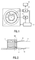
- the MR device shown in FIG. 1 contains a high-frequency coil arrangement 1 with a hollow cylindrical cross-section, which generates a high-frequency magnetic field that is perpendicular to the plane of the drawing and penetrates the examination area in which a patient 2 is located, whose longitudinal body axis runs perpendicular to the plane of the drawing.
- the MR device also has a main field magnet (not shown in more detail) which generates a stationary, homogeneous magnetic field running perpendicular to the plane of the drawing.
- the MR device also has gradient coils, not shown in more detail, which likewise generate magnetic fields running perpendicular to the plane of the drawing, but with a gradient in one of three mutually perpendicular Directions.
- a control unit 3 controls the generation of the fields described above. In particular, it controls an oscillator 4, which is connected to the high-frequency coil arrangement 1, by means of which the high-frequency excitation takes place in the transmission mode. Furthermore, the control unit 3 controls a radio-frequency receiver 5, which is connected to various receiving coils and amplifies, demodulates and digitizes the received nuclear magnetic resonance signals. The signals are then processed in the processing unit 6.
- a cylindrical coil arrangement 7, which encloses part of the body of the patient 2 in a cylindrical manner, and a surface coil arrangement 8, which covers part of the body surface of the patient, are shown here as reception coils.
- FIG. 2 shows an embodiment of the invention for creating coherent MR images from the head and chest area of a patient 2.
- the solenoid arrangement here is a known birdcage resonator 7, which encloses the entire head of a patient 2 up to the neck.
- a birdcage resonator 7 can be used to generate MR images of the head, a single receiving channel having to be provided in the receiver.
- a first surface coil 8 is arranged on the body surface, which is adapted to the body surface, particularly in the neck area.
- the surface coil 8 and the birdcage resonator 7 overlap in an overlap region 100, that is to say the surface coil 8 partially projects into the space enclosed by the birdcage 7.
- a further surface coil 9 adapted to the body surface is arranged in the neck and shoulder region of the patient 2. This is also overlapped by the birdcage resonator 7, ie it also partially projects into the interior thereof.
- a further surface coil 10 is arranged in the back area of the patient 2 and is partially overlapped with the surface coil 9. A total of four reception channels are required for the MR device shown.
- the surface coils 8, 9, 10 are each constructed from a single wire loop.
- the proportion of the surface of the surface coils 8 and 9 that overlaps the birdcage resonator 7 is in practice about 10 to 20% of the total surface of the surface coils 8.9.
- the width of the overlap area is in the range of a few cm. However, the size of the overlap area also depends on the type, design and size of the coils and on the anatomy of the patient.
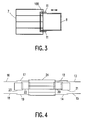
- FIG. 3 A top view of part of the embodiment shown in FIG. 2 is shown in FIG. 3.
- the overlap region 100 of the birdcage resonator 7 and the surface coil 8 can be seen.
- 11 denotes a rail device attached to both sides of the surface coil 8, which slides in a rail (not shown) attached to the birdcage resonator 7.
- the surface coil 8 can be displaced in the direction indicated by the double arrow with respect to the birdcage resonator 7, as a result of which the size of the overlap region 100 changes.
- FIG. 4 shows an alternative embodiment of an MR device according to the invention.
- This includes a birdcage resonator 24 and a large number of surface coils 12 to 23.
- the surface coils 12, 14, 17, 19, 20, 22 adjacent to the birdcage resonator 24 also overlap here with the birdcage resonator 24.
- the further surface coils 13 , 15, 16, 18, 21, 23 each overlap with the adjacent surface coil.
- the embodiment shown is suitable, for example, for creating MR images of an entire leg of a patient.
- the birdcage resonator 24 is arranged, for example, around the knee, the surface coils are distributed over the upper or lower leg.
- the signals received from two surface coils can also be received and processed after processing with a combination circuit on one channel are processed, so that seven reception channels are required for this arrangement.
- any other embodiment is conceivable.
- a further birdcage resonator or a saddle coil arrangement which surrounds the patient's foot can be provided in the end region.
- Two or more solenoid assemblies that partially overlap each other are also conceivable.
- quadrature coils or butterfly coils can also be used as surface coils.
- the surface coil arrangement can also consist of a combination of several different surface coils, with several surface coils, for example a loop and a butterfly coil, being arranged one above the other and covering approximately the same area of the body surface.
- the design of the solenoid arrangement can also differ from the embodiments shown.
- the birdcage can, for example, also have an elliptical cross section and / or have a conductive end surface and / or shoulder openings.
- a further additional decoupling between the surface coil and the solenoid arrangement can take place through a capacitive network between the two coil arrangements if a sufficient improvement in the decoupling is not possible, for example for design reasons, by changing the size of the overlap area.
Landscapes
- Physics & Mathematics (AREA)
- Condensed Matter Physics & Semiconductors (AREA)
- General Physics & Mathematics (AREA)
- Magnetic Resonance Imaging Apparatus (AREA)
Applications Claiming Priority (2)
| Application Number | Priority Date | Filing Date | Title |
|---|---|---|---|
| DE19616464A DE19616464A1 (de) | 1996-04-25 | 1996-04-25 | MR-Gerät mit einer Zylinderspulenanordnung und einer Oberflächenspulenanordnung |
| DE19616464 | 1996-04-25 |
Publications (3)
| Publication Number | Publication Date |
|---|---|
| EP0803736A2 true EP0803736A2 (fr) | 1997-10-29 |
| EP0803736A3 EP0803736A3 (fr) | 1998-04-15 |
| EP0803736B1 EP0803736B1 (fr) | 2008-05-28 |
Family
ID=7792374
Family Applications (1)
| Application Number | Title | Priority Date | Filing Date |
|---|---|---|---|
| EP97201103A Expired - Lifetime EP0803736B1 (fr) | 1996-04-25 | 1997-04-14 | Appareil de RM avec un dispositif de bobines cylindriques et avec un dispositif de bobines de surface |
Country Status (4)
| Country | Link |
|---|---|
| US (1) | US5917324A (fr) |
| EP (1) | EP0803736B1 (fr) |
| JP (1) | JP4097738B2 (fr) |
| DE (2) | DE19616464A1 (fr) |
Cited By (1)
| Publication number | Priority date | Publication date | Assignee | Title |
|---|---|---|---|---|
| WO1999027381A3 (fr) * | 1997-11-26 | 1999-08-12 | Medrad Inc | Reseau vasculaire peripherique de bobines hf d'irm |
Families Citing this family (34)
| Publication number | Priority date | Publication date | Assignee | Title |
|---|---|---|---|---|
| US6027452A (en) | 1996-06-26 | 2000-02-22 | Vital Insite, Inc. | Rapid non-invasive blood pressure measuring device |
| WO1998037438A1 (fr) * | 1997-02-25 | 1998-08-27 | Advanced Imaging Research, Inc. | Ensemble bobinage haute frequence permettant une analyse de resonance |
| US6873156B2 (en) * | 1998-05-06 | 2005-03-29 | Insight Neuroimaging Systems, Llc | Method and apparatus for performing neuroimaging |
| US6711430B1 (en) | 1998-10-09 | 2004-03-23 | Insight Neuroimaging Systems, Inc. | Method and apparatus for performing neuroimaging |
| JP2003511172A (ja) * | 1999-10-11 | 2003-03-25 | コーニンクレッカ フィリップス エレクトロニクス エヌ ヴィ | 感度の重なる領域を具備するmri−rfコイル |
| US6313633B1 (en) * | 1999-12-27 | 2001-11-06 | General Electric Company | Magnetic resonance imaging head coil |
| CA2426324C (fr) * | 2000-10-20 | 2010-09-21 | Insight Neuroimaging Systems, Llc | Ensemble de retenue pour utilisation avec un dispositif d'imagerie par resonance magnetique |
| US6668184B1 (en) | 2000-12-19 | 2003-12-23 | Ge Medical Systems Global Technology Company, Llc | System for and method of synchronizing an image data receiver and an MR imaging acquisition slice |
| US20050283053A1 (en) * | 2002-01-30 | 2005-12-22 | Decharms Richard C | Methods for physiological monitoring, training, exercise and regulation |
| WO2002061457A2 (fr) * | 2001-01-30 | 2002-08-08 | Decharms R Christopher | Procedes de surveillance physiologique, d'entrainement, d'exercice et de regulation |
| US20020103429A1 (en) * | 2001-01-30 | 2002-08-01 | Decharms R. Christopher | Methods for physiological monitoring, training, exercise and regulation |
| US6487436B1 (en) | 2001-04-17 | 2002-11-26 | Ge Medical Systems Global Technology Company, Llc | Switchable field of view apparatus and method for magnetic resonance imaging |
| DE10126338A1 (de) * | 2001-05-30 | 2002-12-12 | Siemens Ag | Hochfrequenz-Spulenanordnung für ein Kernspintomographie-Gerät und Kernspintomorgraphie-Gerät |
| US6630829B1 (en) | 2002-04-22 | 2003-10-07 | Ge Medical Systems Global Technology Co., Llc | Gradient coil set capable of producing a variable field of view |
| US20040092809A1 (en) * | 2002-07-26 | 2004-05-13 | Neurion Inc. | Methods for measurement and analysis of brain activity |
| KR20040013704A (ko) * | 2002-08-08 | 2004-02-14 | 주식회사 아이솔테크놀로지 | 횡전자기파를 이용한 두부용 공명 코일 |
| US6762606B2 (en) * | 2002-11-22 | 2004-07-13 | Igc-Medical Advances, Inc. | Retracting MRI head coil |
| WO2004109300A2 (fr) * | 2003-06-03 | 2004-12-16 | Decharms R Christopher | Procedes de mesure de perturbations de signaux de resonance magnetique |
| US20060155348A1 (en) * | 2004-11-15 | 2006-07-13 | Decharms Richard C | Applications of the stimulation of neural tissue using light |
| ATE477503T1 (de) * | 2005-01-24 | 2010-08-15 | Koninkl Philips Electronics Nv | Orthogonale spule zur kernspintomographie |
| WO2009040677A2 (fr) * | 2007-04-16 | 2009-04-02 | The Governors Of The University Of Calgary | Procédés, dispositifs et systèmes utiles pour un repérage |
| US10076266B2 (en) | 2010-07-07 | 2018-09-18 | Aspect Imaging Ltd. | Devices and methods for a neonate incubator, capsule and cart |
| US10499830B2 (en) | 2010-07-07 | 2019-12-10 | Aspect Imaging Ltd. | Premature neonate life support environmental chamber for use in MRI/NMR devices |
| IL226488A (en) | 2013-05-21 | 2016-07-31 | Aspect Imaging Ltd | Baby crib |
| US11278461B2 (en) | 2010-07-07 | 2022-03-22 | Aspect Imaging Ltd. | Devices and methods for a neonate incubator, capsule and cart |
| US10794975B2 (en) | 2010-09-16 | 2020-10-06 | Aspect Imaging Ltd. | RF shielding channel in MRI-incubator's closure assembly |
| US9597246B2 (en) | 2010-09-16 | 2017-03-21 | Aspect Imaging Ltd. | Premature neonate closed life support system |
| WO2015029044A2 (fr) | 2013-09-02 | 2015-03-05 | Aspect Imaging Ltd. | Incubateur doté d'un mécanisme d'atténuation de bruit et procédé associé |
| US10383782B2 (en) | 2014-02-17 | 2019-08-20 | Aspect Imaging Ltd. | Incubator deployable multi-functional panel |
| US10224135B2 (en) | 2016-08-08 | 2019-03-05 | Aspect Imaging Ltd. | Device, system and method for obtaining a magnetic measurement with permanent magnets |
| US11988730B2 (en) | 2016-08-08 | 2024-05-21 | Aspect Imaging Ltd. | Device, system and method for obtaining a magnetic measurement with permanent magnets |
| US11287497B2 (en) | 2016-08-08 | 2022-03-29 | Aspect Imaging Ltd. | Device, system and method for obtaining a magnetic measurement with permanent magnets |
| US11052016B2 (en) | 2018-01-18 | 2021-07-06 | Aspect Imaging Ltd. | Devices, systems and methods for reducing motion artifacts during imaging of a neonate |
| EP3992656A1 (fr) * | 2020-10-27 | 2022-05-04 | Koninklijke Philips N.V. | Positionnement de bobines de radiofréquence dans des dispositifs d'imagerie par résonance magnétique |
Family Cites Families (18)
| Publication number | Priority date | Publication date | Assignee | Title |
|---|---|---|---|---|
| NL8603006A (nl) * | 1986-11-27 | 1988-06-16 | Philips Nv | Magnetisch resonantie apparaat met gestapeld oppervlakte spoelenstelsel. |
| NL8801018A (nl) * | 1988-04-20 | 1989-11-16 | Philips Nv | Magnetisch resonantie apparaat met ontkoppelde rf-spoelen. |
| JPH0168015U (fr) * | 1987-10-26 | 1989-05-01 | ||
| FI893695A7 (fi) * | 1987-12-07 | 1989-08-04 | Gen Electric | Ydinmagneettinen resonanssi (NMR)-kuvaus usealla pintakäämillä |
| DE3816831A1 (de) * | 1988-05-18 | 1989-11-30 | Philips Patentverwaltung | Kernspinuntersuchungsgeraet mit einer hochfrequenzspulenanordnung |
| JPH01293863A (ja) * | 1988-05-24 | 1989-11-27 | Toshiba Corp | 磁気共鳴イメージング装置 |
| JPH02200243A (ja) * | 1989-01-30 | 1990-08-08 | Yokogawa Medical Syst Ltd | Mriのサーフェースコイル |
| JPH03103230A (ja) * | 1989-09-18 | 1991-04-30 | Toshiba Corp | 磁気共鳴イメージング装置 |
| JPH0420328A (ja) * | 1990-05-14 | 1992-01-23 | Toshiba Corp | Mri装置用受信コイル装置 |
| JPH0549613A (ja) * | 1991-01-11 | 1993-03-02 | Hitachi Medical Corp | 核磁気共鳴装置の受信コイル支持機構 |
| US5258717A (en) * | 1991-08-09 | 1993-11-02 | Medrad, Inc. | Geometrically isolated multiple port volume MRI receiving coil comprising multiple quadrature coils |
| US5510714A (en) * | 1991-08-09 | 1996-04-23 | Hitachi, Ltd. | Magnetic resonance imaging apparatus and RF coil employed therein |
| US5374890A (en) * | 1992-07-24 | 1994-12-20 | Picker International, Inc. | Simultaneous magnetic resonance imaging of multiple human organs |
| DE4225001C1 (de) * | 1992-07-29 | 1993-11-18 | Siemens Ag | Stereotaktische Zusatzeinrichtung für Kernspintomographen |
| US5285160A (en) * | 1992-08-06 | 1994-02-08 | U.S. Philips Corporation | Magnetic resonance apparatus comprising adjacently arranged RF coils systems |
| JP3216938B2 (ja) * | 1993-06-08 | 2001-10-09 | 株式会社日立製作所 | Mri用rfプローブ及び磁気共鳴撮影装置 |
| JP3411631B2 (ja) * | 1993-08-30 | 2003-06-03 | 株式会社日立メディコ | Rfプローブ及び磁気共鳴イメージング装置 |
| EP0695947B1 (fr) * | 1994-08-03 | 2001-11-14 | Philips Patentverwaltung GmbH | Procédé de résonance magnétique pour déterminer la distribution de la magnétisation nucléaire avec un dispositif de bobine de surface |
-
1996
- 1996-04-25 DE DE19616464A patent/DE19616464A1/de not_active Withdrawn
-
1997
- 1997-04-14 DE DE59712942T patent/DE59712942D1/de not_active Expired - Fee Related
- 1997-04-14 EP EP97201103A patent/EP0803736B1/fr not_active Expired - Lifetime
- 1997-04-22 JP JP10479297A patent/JP4097738B2/ja not_active Expired - Fee Related
- 1997-04-23 US US08/842,290 patent/US5917324A/en not_active Expired - Fee Related
Cited By (6)
| Publication number | Priority date | Publication date | Assignee | Title |
|---|---|---|---|---|
| WO1999027381A3 (fr) * | 1997-11-26 | 1999-08-12 | Medrad Inc | Reseau vasculaire peripherique de bobines hf d'irm |
| US6323648B1 (en) | 1997-11-26 | 2001-11-27 | Medrad, Inc. | Peripheral vascular array |
| US6677755B2 (en) | 1997-11-26 | 2004-01-13 | Medrad, Inc. | Circuit for selectively enabling and disabling coils of a multi-coil array |
| US6714012B2 (en) | 1997-11-26 | 2004-03-30 | Medrad, Inc. | Apparatus and method for positioning a patient to obtain images of the vasculature |
| US6737866B2 (en) | 1997-11-26 | 2004-05-18 | Medrad, Inc. | Method of imaging a vasculature of a patient |
| US6747454B2 (en) | 1997-11-26 | 2004-06-08 | Medrad, Inc. | Array of coils for use in imaging the vasculature of a patient |
Also Published As
| Publication number | Publication date |
|---|---|
| DE19616464A1 (de) | 1997-11-06 |
| JP4097738B2 (ja) | 2008-06-11 |
| EP0803736B1 (fr) | 2008-05-28 |
| JPH1043161A (ja) | 1998-02-17 |
| DE59712942D1 (de) | 2008-07-10 |
| US5917324A (en) | 1999-06-29 |
| EP0803736A3 (fr) | 1998-04-15 |
Similar Documents
| Publication | Publication Date | Title |
|---|---|---|
| EP0803736B1 (fr) | Appareil de RM avec un dispositif de bobines cylindriques et avec un dispositif de bobines de surface | |
| DE4422782C2 (de) | Aktiv geschirmte transversale Gradientenspule für Kernspintomographiegeräte | |
| EP0462131B1 (fr) | Systeme magnetique | |
| DE69532220T2 (de) | Scheibenförmiger Magnet zur Bilderzeugung mittels magnetischer Resonanz | |
| DE3616078C2 (fr) | ||
| EP0142077B1 (fr) | Dispositif à haute fréquence dans un appareil pour la résonance de spin nucléaire avec une bobine de surface | |
| DE19534387C2 (de) | Abschirmgradientenspule für ein Kernspin-Tomographiegerät und Kernspin-Tomographiegerät | |
| DE19540746A1 (de) | Magnetresonanz-Abbildungssystem mit modularen Ganzkörper-Gradientenspulen | |
| DE10157039A1 (de) | HF-Spulenanordnung für Magnetresonanz-Bildgerät | |
| DE3411521A1 (de) | Nuklearmagnetische resonanzvorrichtung | |
| DE4142263C2 (de) | Gradientenspulensystem | |
| DE69822709T2 (de) | Offener Magnet für die Magnetresonanzbildgebung mit inhomogenem Feld | |
| DE19610266A1 (de) | Mit kernmagnetischer Resonanz arbeitende bildgebende Vorrichtung unter Verwendung asymmetrischer, drehmomentfreier aktiver Abschirmgradientenspulen | |
| DE10255261A1 (de) | HF-Spulenanordnung für Magnetresonanz-Bildgerät | |
| DE19829298C2 (de) | Gradientenspulensystem für ein Kernspintomographiegerät | |
| DE69836293T2 (de) | Magnetstruktur für einen Kernspinresonanztomographen | |
| DE102005017718B4 (de) | MR-Bildgebungsverfahren und MRI-Spule | |
| EP0797103B1 (fr) | Assemblage d'aimants pour IRM avec deux volumes à imager separés | |
| DE69311296T2 (de) | Vorrichtung zur Erzeugung eines Magnetfeldes für den Gebrauch zur Bilderzeugung mittels magnetischer Resonanz vom supraleitenden Typ | |
| EP0142079B1 (fr) | Dispositif à haute fréquence dans un appareil pour la résonance de spin nucléàire | |
| DE69925956T2 (de) | Shimspulenanordnung und Gradientenspule mit Ausnehmungen für die Magnetresonanzbildgebung | |
| DE4128323C2 (de) | Zirkular polarisierende Lokalantenne für ein Kernspinresonanz-Bildgerät | |
| DE19545222C2 (de) | Gradientenspulen für Therapietomographen | |
| DE19535257A1 (de) | MR-Anordnung zur Bestimmung der Kernmagnetisierungsverteilung mit einer Oberflächenspulen-Anordnung | |
| DE60225039T2 (de) | Rf-spule mit zwei parallelen endleitern |
Legal Events
| Date | Code | Title | Description |
|---|---|---|---|
| PUAI | Public reference made under article 153(3) epc to a published international application that has entered the european phase |
Free format text: ORIGINAL CODE: 0009012 |
|
| AK | Designated contracting states |
Kind code of ref document: A2 Designated state(s): DE FR GB NL |
|
| PUAL | Search report despatched |
Free format text: ORIGINAL CODE: 0009013 |
|
| AK | Designated contracting states |
Kind code of ref document: A3 Designated state(s): DE FR GB NL |
|
| RAP3 | Party data changed (applicant data changed or rights of an application transferred) |
Owner name: KONINKLIJKE PHILIPS ELECTRONICS N.V. Owner name: PHILIPS PATENTVERWALTUNG GMBH |
|
| 17P | Request for examination filed |
Effective date: 19981015 |
|
| RAP3 | Party data changed (applicant data changed or rights of an application transferred) |
Owner name: KONINKLIJKE PHILIPS ELECTRONICS N.V. Owner name: PHILIPS CORPORATE INTELLECTUAL PROPERTY GMBH |
|
| RAP1 | Party data changed (applicant data changed or rights of an application transferred) |
Owner name: KONINKLIJKE PHILIPS ELECTRONICS N.V. Owner name: PHILIPS CORPORATE INTELLECTUAL PROPERTY GMBH |
|
| RAP1 | Party data changed (applicant data changed or rights of an application transferred) |
Owner name: KONINKLIJKE PHILIPS ELECTRONICS N.V. Owner name: PHILIPS INTELLECTUAL PROPERTY & STANDARDS GMBH |
|
| 17Q | First examination report despatched |
Effective date: 20070412 |
|
| GRAP | Despatch of communication of intention to grant a patent |
Free format text: ORIGINAL CODE: EPIDOSNIGR1 |
|
| GRAS | Grant fee paid |
Free format text: ORIGINAL CODE: EPIDOSNIGR3 |
|
| GRAA | (expected) grant |
Free format text: ORIGINAL CODE: 0009210 |
|
| AK | Designated contracting states |
Kind code of ref document: B1 Designated state(s): DE FR GB NL |
|
| REG | Reference to a national code |
Ref country code: GB Ref legal event code: FG4D Free format text: NOT ENGLISH |
|
| REF | Corresponds to: |
Ref document number: 59712942 Country of ref document: DE Date of ref document: 20080710 Kind code of ref document: P |
|
| PG25 | Lapsed in a contracting state [announced via postgrant information from national office to epo] |
Ref country code: NL Free format text: LAPSE BECAUSE OF FAILURE TO SUBMIT A TRANSLATION OF THE DESCRIPTION OR TO PAY THE FEE WITHIN THE PRESCRIBED TIME-LIMIT Effective date: 20080528 |
|
| NLV1 | Nl: lapsed or annulled due to failure to fulfill the requirements of art. 29p and 29m of the patents act | ||
| PLBE | No opposition filed within time limit |
Free format text: ORIGINAL CODE: 0009261 |
|
| STAA | Information on the status of an ep patent application or granted ep patent |
Free format text: STATUS: NO OPPOSITION FILED WITHIN TIME LIMIT |
|
| 26N | No opposition filed |
Effective date: 20090303 |
|
| GBPC | Gb: european patent ceased through non-payment of renewal fee |
Effective date: 20090414 |
|
| REG | Reference to a national code |
Ref country code: FR Ref legal event code: ST Effective date: 20091231 |
|
| PG25 | Lapsed in a contracting state [announced via postgrant information from national office to epo] |
Ref country code: DE Free format text: LAPSE BECAUSE OF NON-PAYMENT OF DUE FEES Effective date: 20091103 |
|
| PG25 | Lapsed in a contracting state [announced via postgrant information from national office to epo] |
Ref country code: GB Free format text: LAPSE BECAUSE OF NON-PAYMENT OF DUE FEES Effective date: 20090414 Ref country code: FR Free format text: LAPSE BECAUSE OF NON-PAYMENT OF DUE FEES Effective date: 20091222 |