EP3992656A1 - Positionnement de bobines de radiofréquence dans des dispositifs d'imagerie par résonance magnétique - Google Patents
Positionnement de bobines de radiofréquence dans des dispositifs d'imagerie par résonance magnétique Download PDFInfo
- Publication number
- EP3992656A1 EP3992656A1 EP20204012.7A EP20204012A EP3992656A1 EP 3992656 A1 EP3992656 A1 EP 3992656A1 EP 20204012 A EP20204012 A EP 20204012A EP 3992656 A1 EP3992656 A1 EP 3992656A1
- Authority
- EP
- European Patent Office
- Prior art keywords
- coil
- relative overlap
- magnetic resonance
- overlap
- coil elements
- Prior art date
- Legal status (The legal status is an assumption and is not a legal conclusion. Google has not performed a legal analysis and makes no representation as to the accuracy of the status listed.)
- Withdrawn
Links
- 238000002595 magnetic resonance imaging Methods 0.000 title claims abstract description 40
- 238000000034 method Methods 0.000 claims abstract description 52
- 230000008569 process Effects 0.000 claims description 25
- 239000011159 matrix material Substances 0.000 claims description 18
- 230000003287 optical effect Effects 0.000 claims description 8
- 230000007246 mechanism Effects 0.000 claims description 7
- 230000001939 inductive effect Effects 0.000 claims description 4
- 238000012544 monitoring process Methods 0.000 claims description 4
- 238000005516 engineering process Methods 0.000 description 12
- 230000001419 dependent effect Effects 0.000 description 6
- 210000003127 knee Anatomy 0.000 description 6
- 230000035945 sensitivity Effects 0.000 description 6
- 238000003491 array Methods 0.000 description 4
- 230000008859 change Effects 0.000 description 4
- 238000006073 displacement reaction Methods 0.000 description 4
- 238000010801 machine learning Methods 0.000 description 4
- 230000006870 function Effects 0.000 description 3
- 238000003384 imaging method Methods 0.000 description 3
- 210000002414 leg Anatomy 0.000 description 3
- 238000002360 preparation method Methods 0.000 description 3
- 230000006978 adaptation Effects 0.000 description 2
- 210000003484 anatomy Anatomy 0.000 description 2
- 239000004020 conductor Substances 0.000 description 2
- 230000008878 coupling Effects 0.000 description 2
- 238000010168 coupling process Methods 0.000 description 2
- 238000005859 coupling reaction Methods 0.000 description 2
- 230000009193 crawling Effects 0.000 description 2
- 238000001514 detection method Methods 0.000 description 2
- 238000010586 diagram Methods 0.000 description 2
- 230000000007 visual effect Effects 0.000 description 2
- 238000013473 artificial intelligence Methods 0.000 description 1
- 210000004204 blood vessel Anatomy 0.000 description 1
- 210000000746 body region Anatomy 0.000 description 1
- 230000005415 magnetization Effects 0.000 description 1
- 238000005259 measurement Methods 0.000 description 1
- 230000009467 reduction Effects 0.000 description 1
- 230000029058 respiratory gaseous exchange Effects 0.000 description 1
- 230000002123 temporal effect Effects 0.000 description 1
- 210000000689 upper leg Anatomy 0.000 description 1
Images
Classifications
-
- G—PHYSICS
- G01—MEASURING; TESTING
- G01R—MEASURING ELECTRIC VARIABLES; MEASURING MAGNETIC VARIABLES
- G01R33/00—Arrangements or instruments for measuring magnetic variables
- G01R33/20—Arrangements or instruments for measuring magnetic variables involving magnetic resonance
- G01R33/28—Details of apparatus provided for in groups G01R33/44 - G01R33/64
- G01R33/32—Excitation or detection systems, e.g. using radio frequency signals
- G01R33/34—Constructional details, e.g. resonators, specially adapted to MR
- G01R33/34007—Manufacture of RF coils, e.g. using printed circuit board technology; additional hardware for providing mechanical support to the RF coil assembly or to part thereof, e.g. a support for moving the coil assembly relative to the remainder of the MR system
-
- G—PHYSICS
- G01—MEASURING; TESTING
- G01R—MEASURING ELECTRIC VARIABLES; MEASURING MAGNETIC VARIABLES
- G01R33/00—Arrangements or instruments for measuring magnetic variables
- G01R33/20—Arrangements or instruments for measuring magnetic variables involving magnetic resonance
- G01R33/28—Details of apparatus provided for in groups G01R33/44 - G01R33/64
- G01R33/32—Excitation or detection systems, e.g. using radio frequency signals
- G01R33/34—Constructional details, e.g. resonators, specially adapted to MR
- G01R33/34084—Constructional details, e.g. resonators, specially adapted to MR implantable coils or coils being geometrically adaptable to the sample, e.g. flexible coils or coils comprising mutually movable parts
-
- G—PHYSICS
- G01—MEASURING; TESTING
- G01R—MEASURING ELECTRIC VARIABLES; MEASURING MAGNETIC VARIABLES
- G01R33/00—Arrangements or instruments for measuring magnetic variables
- G01R33/20—Arrangements or instruments for measuring magnetic variables involving magnetic resonance
- G01R33/28—Details of apparatus provided for in groups G01R33/44 - G01R33/64
- G01R33/32—Excitation or detection systems, e.g. using radio frequency signals
- G01R33/36—Electrical details, e.g. matching or coupling of the coil to the receiver
- G01R33/3642—Mutual coupling or decoupling of multiple coils, e.g. decoupling of a receive coil from a transmission coil, or intentional coupling of RF coils, e.g. for RF magnetic field amplification
- G01R33/365—Decoupling of multiple RF coils wherein the multiple RF coils have the same function in MR, e.g. decoupling of a receive coil from another receive coil in a receive coil array, decoupling of a transmission coil from another transmission coil in a transmission coil array
-
- G—PHYSICS
- G01—MEASURING; TESTING
- G01R—MEASURING ELECTRIC VARIABLES; MEASURING MAGNETIC VARIABLES
- G01R33/00—Arrangements or instruments for measuring magnetic variables
- G01R33/20—Arrangements or instruments for measuring magnetic variables involving magnetic resonance
- G01R33/28—Details of apparatus provided for in groups G01R33/44 - G01R33/64
- G01R33/32—Excitation or detection systems, e.g. using radio frequency signals
- G01R33/34—Constructional details, e.g. resonators, specially adapted to MR
- G01R33/341—Constructional details, e.g. resonators, specially adapted to MR comprising surface coils
- G01R33/3415—Constructional details, e.g. resonators, specially adapted to MR comprising surface coils comprising arrays of sub-coils, i.e. phased-array coils with flexible receiver channels
Definitions
- the present invention relates to a system for magnetic resonance imaging, a method for generating images by magnetic resonance imaging and a program element.
- High patient throughput is crucial for magnetic resonance imaging devices, in particular in medical facilities. Thus, ensuring a smooth imaging process is of particular importance.
- radiofrequency coils are commonly used.
- the radiofrequency coils are configured to excite the magnetization by broadcasting the radiofrequency power as well as to receive the signal from the excited spins.
- the radiofrequency coils directly affect the spatial and temporal resolution, sensitivity, and uniformity in magnetic resonance imaging. Therefore, a correct positioning of the receiving coils is crucial for a good image quality. Due to that, usually only trained and experienced staff members are allowed to operate magnetic resonance imaging devices. Understaffing, e.g. due to illness, holidays etc., and/or operating of the magnetic resonance imaging device by unexperienced staff members lead to cancellation and/or delay of the planned schedule. Therefore, the workflows are becoming increasingly autonomous and automated, wherein a correct positioning of the coils is of particular importance.
- Wireless radiofrequency coil technology offers convenience and ease of operation for handling and positioning of the coils, in particular for increasingly autonomous and automated workflows.
- the increasingly autonomous and automated workflows rises the challenge of guaranteeing a sufficiently good and constant image quality.
- a system for magnetic resonance imaging comprising a magnetic resonance imaging device, and a control unit configured to control the magnetic resonance imaging device.
- the magnetic resonance imaging device comprises a magnetic resonance bore, a movable table configured to be movable in and out of the magnetic resonance bore, and at least two coil elements of at least one coil.
- the two coil elements are configured to be adjacently positioned with a relative overlap, and to be relatively movable to each other on the movable table.
- the control unit comprises a coil element detecting unit configured to detect the at least two coil elements, an overlap detecting unit configured to detect the relative overlap of the at least two coil elements, a determining unit configured to determine whether the detected relative overlap is within a predefined critical range, and a position adapting unit configured to adapt the relative position of the coil elements when the detected relative overlap is outside the predefined critical range.
- Such a system for magnetic resonance imaging (MRI) may allow autonomously detecting of and guiding to an optimal relative overlap of the at least two coil elements.
- the optimal relative overlap may be defined by as a value within a so called "critical range" allowing a fast reconstruction of images and a good image quality.
- the critical range may be defined by a preset lower limit value and a preset upper limit value between which a homogeneous B1 sensitivity and a good signal-to-noise-ratio may be provided.
- the predefined critical range may be stored in the control unit.
- the homogeneous B1 sensitivity defines the magnetic field sensitivity of the reconstructed image.
- the homogeneity of the magnetic field is directly proportional to an intensity variation in the image, meaning pixel values in the image.
- Local variation of B1 meaning varying pixel values in the image, may lead to undesired spatially varying image signals and contrast.
- the more homogeneous the B1 sensitivity the better the image quality.
- a good signal-to-noise-ratio may be defined as the independency of the noise from the different coil elements, which may be achieved within the predefined critical range.
- the signal-to-noise-ratio may be determined using the noise-correlation matrix.
- the image quality is dependent on the number of present artifacts.
- the artifacts can occur due to breathing of a patient and/or due to blood vessels. Hence, those artifacts can hardly be prevented. Additionally, the artifacts can occur due to an unfavorable signal-to-noise ratio.
- the signal-to-noise ratio corresponds to a measureable value for the presence and intensity of noise due to undesired signal-correlation of adjacently arranged coil elements. Within the predefined critical range, the signal-to-noise ratio is close to an optimum defining a minimal influence on the image quality.
- the movable table as used herein is to be understood as a table or a couch, on which a patient is placed at least for the duration of the magnetic resonance image generating process, and may also be referred to as a patient table.
- the movable table may comprise at least one coil, preferably several coils, embedded into a bed surface of the movable table.
- the embedded coils may be selectively tuned or detuned by the control unit to achieve the optimal arrangement for the image generating process to be performed.
- the at least one coil may be a receiving coil that is usually placed on a patient's body. Additionally or alternatively, there may be applications where a relative overlap of transmit coils, and/or combinations of transmit and receiving coils may be applied.
- One coil may comprise at least one coil segment comprising several coil elements. The coil elements of one coil segment may be pre-fixedly arranged relative to each other such that an interference of signals of adjacent coil elements is so low that the image quality is barely affected.
- the at least two coil elements of at least one coil may relate to coil elements being arranged at outer edge areas of the at least one coil.
- the coil setup may be dependent on the region to be imaged and/or the individually selected anatomy as well as on a coil size and/or a patient's body size.
- the position adapting unit as used herein is to be understood as comprising an audio guidance and/or a video guidance as well as an automated positioning.
- the position adapting unit may be configured to support a manual adaption of the coil position, e.g., performed by the patient, by providing an audio guidance, e.g. by an audio output of position adaptation orders and/or an optical guidance, e.g. by displaying the required displacement of the coil, by showing the actual position of the coil and the required position of the coil.
- the position adapting unit may be configured to automatically adapt the position of the coil without a human intervention.
- the coil may be provided with software-controlled actuators being controlled by the position adapting unit.
- control unit particularly the position adapting unit, may be configured to automatically select and detune individual coil elements, especially of wireless radiofrequency coils, to achieve the relative overlap being within the predefined critical range.
- the system may allow patient engagement e.g., through autonomous preparation of the patient by himself without an experienced staff member being physically present.
- the system may guide the patient through the preparation process, e.g. including the selection of the correct coils and the positioning of the coils such that the relative overlap is within the predefined critical range.
- the system for magnetic resonance imaging may allow an increased patient throughput as the performance is at least less dependent on the presence of a skilled staff member. Further, the system may allow an improved image quality by adapting the relative overlap of adjacently positioned overlapping coil elements to a position in which the signal-to noise-ratio barely affects the image quality.
- the magnetic resonance imaging device may comprise a computing unit configured to perform an image generating process.
- the control unit which in configured to control the magnetic resonance imaging device, controls the computing unit for performing an image generating process.
- the control unit may be a state machine capable of machine learning.
- Machine learning corresponds to a computer-implemented method for accessing and/or collecting data and using the data to learn for themselves.
- machine learning is an application of artificial intelligence (AI) enabling systems to automatically learn and improve from experience, e.g. based on collected data, without being explicitly programmed.
- the control unit may use data from e.g., the coil element detecting unit, the overlap detecting unit, the determining unit and/or the position adapting unit. Additionally, the control unit may have access to a hospital and/or patient database.
- the at least two coil elements may be from different coils. There may be applications in which the use of more than one coil is required. To ensure a seamless imaging, the at least two coils should be positioned overlapping each other. In such case, the coil elements arranged at the outer edge area of each coil may be positioned overlapping each other. In case of only one coil, the coil may be flexible and wrapped around a part of a patient's body, e.g., a knee, and the coil element of opposing outer edge areas of the coil may be positioned overlapping each other.
- the at least one coil may have the form of a flat thin blanket-like pad.
- a coil may be flexible in shape such that the coil may be wrapped around a part of a patient's body as described above.
- such a coil may be placed flat onto a part of the patient's body, e.g. on hip, neck or chest.
- other coil types may be used, e.g. a volume coil, a surface coil etc.
- the at least one coil may be wireless or non-wireless.
- Non-wireless coils may comprise a connection wire to connect the coil with either the control unit or an interface of the computing unit.
- Non-wireless coil may comprise more than one coil segment to cover a whole body region, e.g. the coil covering a leg may comprise two coil segments.
- One coil segment may be configured to be placed onto a thigh and the other one may be configured to be placed onto a lower leg, wherein both coil segments may be positioned overlapping each other at the knee.
- Such coil segments may be at least partially pre-arranged, because all coil segments may be connected to the same connection wire.
- Wireless coils may simplify coil handling, especially when being placed by an unexperienced person, e.g., the patient himself or an unskilled operator for an autonomous image acquisition.
- the coil element detecting unit may comprise at least one sensor configured to detect markers of the coils.
- the sensor may be selected of the 2D-sensor group of optical video sensor, capacitive sensor, and inductive sensor, or the sensor may be selected of the 3D-video sensor group of radar sensor, lidar sensor and infrared sensor.
- the coils, particularly the non-wireless coils may comprise optical markers, which can be optical, capacitive or inductive sensible by a corresponding sensor of the coil element detecting unit.
- the markers may have a predefined position on the respective coil, such that a guidance to achieve a relative overlap within the predefined critical range is provided by the markers being detected by the coil element detecting unit.
- the coils, particularly wireless radiofrequency coils may be equipped with color/sensor coded areas to support the guidance to achieve the relative overlap within the predefined critical range.
- an audio device may be individually activated to support the optical guidance.
- the coils may comprise individual passive or active markers, e.g. regions, to provide contrast for the detection with the 3D-video sensor.
- the active markers may be modulated and detected by correlation with respect to a reference signal so that active markers may be run with extreme low power requirement.
- the at least one coil may comprise sensing flexible areas.
- the flexible areas may be stretchable. By stretching the flexible areas of a coil, the relative overlap between this coil and the adjacently positioned coil may be adapted, particularly by sensing integrated in the flexible areas.
- the flexible areas may have markers configured to change their distance as function of stretching.
- the sensing technology integrated in the stretched area may provide a measuring signal for detecting the relative overlap.
- the flexible area may be configured as a flexible latch or strap containing flexible coil conductors or coil electronics to realize a guided adaption of the relative overlap.
- the relative overlap may be fixed using mechanical latches, e.g. Velcro, recess or fixation clamps.
- the flexible areas may comprise markers to be sensed by the coil element detecting unit.
- the stretchable areas may include coil conductor or coil electronics.
- the magnetic resonance imaging device may further comprise at least one coil holder, configured to hold the at least one coil in a predefined position.
- the coil holder may be made for adhering to clothes or may be a harness.
- the coil may be fixed to the coil holder, preferably with fixations and markers for individual coil positioning detection.
- the coil holder and/or the coil may be equipped with sensing technology to detect the relative overlap being within the predefined critical range dependent on the individual size of the patient.
- the coil holder may further be configured to hold the at least one coil in position during the image generating process for preventing a displacement of the coil, particularly a displacement causing the relative overlap moving outside the predefined critical range.
- the coil holder may be applicable to wireless and non-wireless coils and may be combinable with all position adapting guidance technology mentioned above.
- the coil may comprise an outer cover and an inner core, which is configured to slide laterally in two dimensions within the outer cover.
- the coil may be a surface coil that can be applied to a patient at just approximately correct position manually and then may be fixed, e.g. by the patient himself.
- the inner core may comprise the coil elements, and be moved relative to the outer cover by integrated software-controlled actuators.
- the inner core may be movable in two lateral, flat dimensions of the surface coil to achieve that the relative overlap is within the predefined critical range. Such coils are of particular use when arranged under a patient's body, or for the coils being integrated in the movable table.
- a method for generating images by magnetic resonance imaging comprises the steps of positioning at least two coil elements of at least one coil with relative overlap to each other on a movable table, preferably on a patient's body lying on the movable table, detecting the relative overlap of the coil elements, determining whether the detected relative overlap is within a predefined critical range, repeating the preceding steps, when the detected relative overlap is outside the predefined critical range; and starting an image generating process, when the detected relative overlap is within the predefined critical range and the movable table in a final position for generating images.
- the method may be at least partly computer-implemented, and may be implemented in software and/or in hardware.
- This method may allow autonomously detecting of and guiding to an optimal relative overlap of the at least two coil elements.
- the method may allow patient engagement e.g., through autonomous preparation of the patient by himself without an experienced staff member being physically present.
- the method may guide the patient through the positioning of the coils such that the relative overlap is within the predefined critical range. Therefore, the method may allow an automated and autonomous magnetic resonance image acquisition process ensuring a good image quality.
- the method may additionally comprise the steps of monitoring the relative overlap of the coil elements during the image generating process, and re-positioning the coil elements during the image generating process, when the monitored relative overlap is detected to be outside the predefined critical range.
- Monitoring the relative overlap of the coil elements during the image generating process may allow detecting any change of the relative overlap and therefore, timely reacting to such change.
- the repositioning of the coil elements during the image generating process may only be applicable when using coils configured to be automatically positioned by the position adapting unit, as the patient may be not allowed to move during the image generating process.
- the influence of the displaced relative overlap on the image quality may be estimated, and if necessary, the image generating process may be stopped prematurely, the coil elements may be re-positioned manually and the image generating process may be restarted at the beginning.
- the step of detecting a relative overlap of the coil elements may comprise determining a noise-correlation-matrix.
- the noise-correlation-matrix is a measurement value for the signal-to-noise ratio.
- the noise-correlation matrix may be acquired by measuring the electrical signals of the individual coil elements.
- the noise-correlation-matrix may be estimated by an AI-algorithm of the control unit, or by the external 3D-sensing or by coil internal sensing.
- the noise-correlation-matrix may be preferably determined by using local and/or distributed transmitters in the movable table, in the coils themselves, or in the bore of the MR system.
- the noise-correlation-matrix and/or a signal coupling may be determined by individual digital transceivers located in a wireless coil. Different coil elements may be individually activated for detecting the relative overlap and to generate a corresponding feedback signal for guiding the positioning of the coil as mentioned above.
- the step of determining whether the detected relative overlap is within a predefined critical range may comprise comparing the measured noise-correlation-matrix with a predefined noise-correlation-matrix-threshold and based on the comparison result, determining if the detected relative overlap is within the predefined critical range.
- the predefined noise-correlation-matrix threshold may differ depending on the area to be imaged.
- the predefined noise-correlation-matrix may be stored in the control unit and may be adapted by the control unit through a machine learning process.
- the step of positioning the at least two coil elements may further comprise detecting markers provided on the coil or a coil holder, visually and/or audibly guiding a manual positioning of the coil elements based on the detected position of markers into a position corresponding to a relative overlap within the predefined critical range.
- the visual and/or audio guiding process may support the manual positioning of the coil elements and thereby, may accelerate the positioning process.
- the step of positioning at least two coil elements of at least one coil may further comprise an automatic positioning of the at least one coil based on at least one software-controlled mechanism integrated in the coil.
- the automatic positioning of the coils by software-controlled mechanism may comprise the surface coils having an outer cover and an inner core, wherein the inner core is movable within the outer cover, as outlined above.
- Another software-controlled mechanism for automatically position the coil may comprise the coil being equipped with a crawl-mechanism allowing the coil to crawl on the patient, e.g. guided by the position adapting unit. Once the correct position is achieved, the coil may be fixed in position, e.g. by the patient.
- the crawling mechanism may be implemented based on conservation of inertia, e.g. some relatively large mass inside the coil may be first jerked aside laterally and rapidly by an actuator and then moved back more slowly.
- the conservation of inertia may cause the coils to move during the rapid motion because friction between coil and patient may be exceeded. During the more slowly return motion, the friction may be not exceeded and therefore may hold the coil in place. In other words, fast motion and slow return of the mass being repeated rapidly but at slow amplitude may effectively cause the coil crawling along the patient's body.
- the method may further comprise the step of moving the movable table in the final position, wherein moving the movable table in the final position is executed after it is determined that the detected relative overlap is within the predefined critical range or while executing the necessary steps to achieve that the relative overlap is within the predefined critical range.
- moving the table in the final position may be executed during the positioning of the coils for achieving that the relative overlap is within the predefined critical range.
- a program element configured to be stored on a control unit of a system according to first aspect, and configured to cause the system to execute a method according to the second aspect.
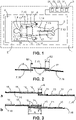
- Fig. 1 shows an exemplary embodiment of a system 1 for magnetic resonance imaging in a schematic illustration.
- the system 1 comprises a magnetic resonance imaging device 2 and a control unit 3, wherein the control unit 3 is configured to control the magnetic resonance imaging device 2.
- the magnetic resonance imaging device 2 comprises a magnetic resonance bore 4, a movable table 5 configured to transport a patient 6 in and out of the magnetic resonance bore 4, and several coils 7.
- Fig. 1 there are shown exemplarily and schematically a head coil 8, two shoulder coils 9, a neck coil 10, a first anterior coil 11, a second anterior coil 12, and two leg coils 13.
- Several coils 7 can be grouped, as exemplarily shown by an upper-body-section 14 comprising the head coil 8, the two shoulder coils 9 and the neck coil 10. Combinations of coils 7 may be selected as function of region to be imaged and/or individually selected anatomy.
- Each coil 7 comprises several coil elements 15 being fixedly arranged to each other integrated into a coil body 16 (e.g., see Figs. 2 ).
- the arrangement of the coils 7, as shown in Fig. 1 illustrates overlapping areas 17, in which adjacently arranged coils 7 overlap with each other. Within the overlapping areas 17, coil elements 15 of the adjacently arranged coils 7 are positioned overlapping each other.
- Such a relative overlap R (e.g., see Fig. 2 ) of adjacently arranged coil elements 15 can cause a noise due to inductively coupled signals of the adjacently arranged coil elements 15.
- This noise directly affects the quality of the reconstructed images of the magnetic resonance imaging device 2, wherein there is a critical range in which the relative overlap R provides a homogeneous B1 sensitivity, and prevents a reduction of the signal-to-noise ratio, resulting in a good image quality.
- the adjacently arranged coil elements 15 are not optimally inductively decoupled resulting in a signal-to-noise-ratio loss causing image artifacts depending on an image sequence and an image reconstruction algorithm.
- the control unit 3 comprises a coil element detecting unit 31, an overlap detecting unit 32, a determining unit 33 and a position adapting unit 34.
- the coil element detecting unit 31 is configured to detect adjacently arranged overlapping coil elements 15.
- the overlap detecting unit 32 is configured to detect the relative overlap R of the adjacently arranged overlapping coil elements 15. Both units 31, 32 can be provided separately or integrated to each other.
- the coil elements 15 may be detected by markers (not illustrated) being provided on the coils 7.
- the markers can be sensed by the coil element detecting unit 31 and/or the overlap detecting unit 32.
- the coil element detecting unit 31 and the overlap detecting unit 32 can comprise 2D-sensing technology, sensing optical, capacitive or inductive markers and/or an external 3D-sensing technology to detect passive or active markers providing contrast areas, which can be detected by the 3D-sensing technology, e.g. radar, lidar or infrared sensors.
- the determining unit 33 is configured to determine whether the detected relative overlap R being detected by the overlap detecting unit 32 is within the critical range, e.g. by determining an actual noise-correlation-matrix, comparing the actual noise-correlation matrix with a predefined noise-correlation-matrix-threshold, to determine, based on the comparison result, whether the detected relative overlap R is within the critical range. Additionally or alternatively, the determining unit 33 may determine whether the detected relative overlap R is within the critical range based on the results of the overlap detecting unit 32.
- the position adapting unit 34 is configured to adapt the relative position of the adjacently arranged overlapping coil elements 15, when the detected relative overlap R is outside the critical range.
- the position adapting unit 34 can comprise an audio guidance device and/or a video guidance device (not illustrated) for supporting a manual adaption of the coil position, e.g., performed by the patient 6.
- the audio guidance device can provide an audio guidance, e.g. by an audio output of position adaptation orders and/or the video guidance device can provide an optical guidance, e.g. by displaying the required displacement of the coil 7, by showing the actual position of the coil 7 and the required position of the coil 7.
- the position adapting unit 34 can comprise an automated positioning device configured to automatically adapt the position of the coil 7 without a human intervention.
- the coil 7 may be provided with software-controlled actuators being controlled by the position adapting unit 34.
- the position adapting unit 34 may be configured to automatically select and detune individual coil elements 15, especially of coil 7 being wireless radiofrequency coils, to achieve the relative overlap R being within the predefined critical range.
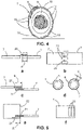
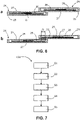
- Figs. 2 to 6 show several exemplary embodiments of arranging coils 7 to achieve a relative overlap being within the critical range.
- Fig. 2 three coils 7 each being formed as a thin flat blanket-like pad are arranged such that the coil elements 15 arranged in outer edge areas of the coils 7, are positioned overlapping each other.
- the thin flat blanket-like coil 7 may be formed of arranging coil elements 15 in arrays (not illustrated), wherein the arrays are fixedly arranged adjacent to each other to form the coil 7.
- the coil elements 15 shown in Fig. 2 each correspond to one coil element 15 of one coil element array.
- the relative overlap R1 between a first pair of overlapping coils 7 illustrates a lower limit value for the critical range and the relative overlap R2 between a second pair of overlapping coils 7 illustrates an upper limit value for the critical range defining the range in which the relative overlap R may not negatively affect the image reconstruction.
- Whether the relative overlap R is within the critical range may be determined by determining a noise-correlation-matrix.
- the noise-correlation-matrix, and thereby a signal coupling of adjacently arranged overlapping coil elements 15, can be measured by individual digital transceivers (not illustrated) located in the coils 7.
- step S2 the relative overlap R of the coil elements 15 is detected, e.g. by measuring a noise-correlation-matrix, preferably by the overlap detecting unit 21.
- step S3 it is determined, preferably by the determining unit 33 of the control unit 3, whether the detected relative overlap R is within a predefined critical range, e.g. by comparing the measured noise-correlation-matrix with a predefined noise-correlation-matrix-threshold and based on the comparison result, determining if the detected relative overlap is within the predefined critical range.
- step S4 When the detected relative overlap R is outside the predefined critical range; the steps S1 to S3 are repeated (step S4) until the detected relative overlap R is within the predefined critical range, then an image generating process is started, when the movable table 5 in a final position for generating images (step S5).
- the following steps not being illustrated in Fig 7 may additionally be comprised by the method 100: a step of monitoring the relative overlap R of the coil elements 15 during the image generating process, and a step of re-positioning the coil elements 15 automatically during the image generating process, when the monitored relative overlap R is detected to be outside the predefined critical range.
Priority Applications (6)
| Application Number | Priority Date | Filing Date | Title |
|---|---|---|---|
| EP20204012.7A EP3992656A1 (fr) | 2020-10-27 | 2020-10-27 | Positionnement de bobines de radiofréquence dans des dispositifs d'imagerie par résonance magnétique |
| US18/031,170 US20230384403A1 (en) | 2020-10-27 | 2021-10-25 | Positioning of radiofrequency coils in magnetic resonance imaging devices |
| PCT/EP2021/079506 WO2022090137A1 (fr) | 2020-10-27 | 2021-10-25 | Positionnement de bobines radiofréquences dans des dispositifs d'imagerie par résonance magnétique |
| CN202180073549.1A CN116868074A (zh) | 2020-10-27 | 2021-10-25 | 射频线圈在磁共振成像设备中的定位 |
| EP21793968.5A EP4237865A1 (fr) | 2020-10-27 | 2021-10-25 | Positionnement de bobines radiofréquences dans des dispositifs d'imagerie par résonance magnétique |
| JP2023525468A JP2023546620A (ja) | 2020-10-27 | 2021-10-25 | 磁気共鳴イメージングデバイスにおける高周波コイルの配置 |
Applications Claiming Priority (1)
| Application Number | Priority Date | Filing Date | Title |
|---|---|---|---|
| EP20204012.7A EP3992656A1 (fr) | 2020-10-27 | 2020-10-27 | Positionnement de bobines de radiofréquence dans des dispositifs d'imagerie par résonance magnétique |
Publications (1)
| Publication Number | Publication Date |
|---|---|
| EP3992656A1 true EP3992656A1 (fr) | 2022-05-04 |
Family
ID=73029875
Family Applications (2)
| Application Number | Title | Priority Date | Filing Date |
|---|---|---|---|
| EP20204012.7A Withdrawn EP3992656A1 (fr) | 2020-10-27 | 2020-10-27 | Positionnement de bobines de radiofréquence dans des dispositifs d'imagerie par résonance magnétique |
| EP21793968.5A Pending EP4237865A1 (fr) | 2020-10-27 | 2021-10-25 | Positionnement de bobines radiofréquences dans des dispositifs d'imagerie par résonance magnétique |
Family Applications After (1)
| Application Number | Title | Priority Date | Filing Date |
|---|---|---|---|
| EP21793968.5A Pending EP4237865A1 (fr) | 2020-10-27 | 2021-10-25 | Positionnement de bobines radiofréquences dans des dispositifs d'imagerie par résonance magnétique |
Country Status (5)
| Country | Link |
|---|---|
| US (1) | US20230384403A1 (fr) |
| EP (2) | EP3992656A1 (fr) |
| JP (1) | JP2023546620A (fr) |
| CN (1) | CN116868074A (fr) |
| WO (1) | WO2022090137A1 (fr) |
Citations (5)
| Publication number | Priority date | Publication date | Assignee | Title |
|---|---|---|---|---|
| EP0338624A1 (fr) * | 1988-04-20 | 1989-10-25 | Koninklijke Philips Electronics N.V. | Appareil à résonance magnétique muni de bobines HF découplées |
| US5552707A (en) * | 1993-08-30 | 1996-09-03 | Hitachi Medical Corporation | RF probe which can vary distance between receiving coils which face each other |
| US20100259262A1 (en) * | 2009-04-10 | 2010-10-14 | Nobuyasu Ichinose | Magnetic resonance imaging apparatus |
| WO2014044635A1 (fr) * | 2012-09-18 | 2014-03-27 | Koninklijke Philips N.V. | Linac guidé par résonance magnétique |
| US20190369181A1 (en) * | 2018-05-31 | 2019-12-05 | General Electric Company | Method and systems for coil selection in magnetic resonance imaging to reduce annefact artifact |
-
2020
- 2020-10-27 EP EP20204012.7A patent/EP3992656A1/fr not_active Withdrawn
-
2021
- 2021-10-25 US US18/031,170 patent/US20230384403A1/en active Pending
- 2021-10-25 WO PCT/EP2021/079506 patent/WO2022090137A1/fr active Application Filing
- 2021-10-25 JP JP2023525468A patent/JP2023546620A/ja active Pending
- 2021-10-25 EP EP21793968.5A patent/EP4237865A1/fr active Pending
- 2021-10-25 CN CN202180073549.1A patent/CN116868074A/zh active Pending
Patent Citations (5)
| Publication number | Priority date | Publication date | Assignee | Title |
|---|---|---|---|---|
| EP0338624A1 (fr) * | 1988-04-20 | 1989-10-25 | Koninklijke Philips Electronics N.V. | Appareil à résonance magnétique muni de bobines HF découplées |
| US5552707A (en) * | 1993-08-30 | 1996-09-03 | Hitachi Medical Corporation | RF probe which can vary distance between receiving coils which face each other |
| US20100259262A1 (en) * | 2009-04-10 | 2010-10-14 | Nobuyasu Ichinose | Magnetic resonance imaging apparatus |
| WO2014044635A1 (fr) * | 2012-09-18 | 2014-03-27 | Koninklijke Philips N.V. | Linac guidé par résonance magnétique |
| US20190369181A1 (en) * | 2018-05-31 | 2019-12-05 | General Electric Company | Method and systems for coil selection in magnetic resonance imaging to reduce annefact artifact |
Also Published As
| Publication number | Publication date |
|---|---|
| WO2022090137A1 (fr) | 2022-05-05 |
| JP2023546620A (ja) | 2023-11-06 |
| CN116868074A (zh) | 2023-10-10 |
| US20230384403A1 (en) | 2023-11-30 |
| EP4237865A1 (fr) | 2023-09-06 |
Similar Documents
| Publication | Publication Date | Title |
|---|---|---|
| US9250305B2 (en) | Adaptable sheet of coils | |
| US9453894B2 (en) | Sheet of surface coils for imaging applications | |
| CN102764121B (zh) | 用于感应地通信数据的系统和方法 | |
| US9808174B2 (en) | Magnetic-resonance imaging diagnosis apparatus and magnetic-resonance imaging method | |
| EP2568307A1 (fr) | Amélioration du positionnement du patient dans un appareil d'IRM | |
| US20100189328A1 (en) | Method of automatically acquiring magnetic resonance image data | |
| JP2018518300A (ja) | 効率的なmriワークフローのために金属インプラントを検出し磁気共鳴パルスシーケンスを選択するための方法及び検出ユニット | |
| KR102346071B1 (ko) | 로우-필드, 다중-채널 이미징을 위한 시스템 및 방법 | |
| US10191131B2 (en) | Medical imaging apparatus having multiple subsystems, and operating method therefor | |
| US20110218424A1 (en) | Magnetic resonance imaging apparatus and control method thereof | |
| CN111480089B (zh) | 具有运动检测的磁共振成像系统 | |
| KR20160038796A (ko) | 복수의 서브시스템들을 포함하는 의료 이미징 검사 디바이스의 동작 | |
| US9839371B2 (en) | Method and apparatus for capture of physiological signals and image data | |
| KR20160038799A (ko) | 복수의 서브시스템들을 포함하는 의료 이미징 검사 디바이스의 동작 | |
| US10036795B2 (en) | Method for the adjustment of at least one magnetic resonance image data set of a movable examination object and correspondingly designed magnetic resonance device | |
| CN103424722A (zh) | 磁共振成像的颈部线圈设备 | |
| US10031199B2 (en) | Implementation of a magnetic resonance examination at several bed positions in the scanner | |
| EP3992656A1 (fr) | Positionnement de bobines de radiofréquence dans des dispositifs d'imagerie par résonance magnétique | |
| US20140320128A1 (en) | Method and magnetic resonance apparatus to acquire image data sets of an examination subject | |
| US20180268569A1 (en) | Method and medical imaging apparatus for detecting abnormalities in medical image data of a region of a patient outside of a region to be examined | |
| US11163029B2 (en) | MRI system with improved navigator | |
| JPH0268036A (ja) | 核磁気共鳴イメージング装置 | |
| US20170059678A1 (en) | Method and magnetic resonance apparatus for determining a scanning region relevant to a magnetic resonance examination | |
| KR20180089247A (ko) | 자기 공명 영상 디스플레이 장치 및 자기 공명 영상 디스플레이 방법 | |
| CN112438718A (zh) | 定位检查床的方法、磁共振设备、程序产品和数据载体 |
Legal Events
| Date | Code | Title | Description |
|---|---|---|---|
| PUAI | Public reference made under article 153(3) epc to a published international application that has entered the european phase |
Free format text: ORIGINAL CODE: 0009012 |
|
| STAA | Information on the status of an ep patent application or granted ep patent |
Free format text: STATUS: THE APPLICATION HAS BEEN PUBLISHED |
|
| AK | Designated contracting states |
Kind code of ref document: A1 Designated state(s): AL AT BE BG CH CY CZ DE DK EE ES FI FR GB GR HR HU IE IS IT LI LT LU LV MC MK MT NL NO PL PT RO RS SE SI SK SM TR |
|
| STAA | Information on the status of an ep patent application or granted ep patent |
Free format text: STATUS: THE APPLICATION IS DEEMED TO BE WITHDRAWN |
|
| 18D | Application deemed to be withdrawn |
Effective date: 20221105 |