EP0802534B1 - Lademechanismus zum Laden eines Informationsträgers in ein Aufzeichnungs-/Wiedergabegerät - Google Patents
Lademechanismus zum Laden eines Informationsträgers in ein Aufzeichnungs-/Wiedergabegerät Download PDFInfo
- Publication number
- EP0802534B1 EP0802534B1 EP97106493A EP97106493A EP0802534B1 EP 0802534 B1 EP0802534 B1 EP 0802534B1 EP 97106493 A EP97106493 A EP 97106493A EP 97106493 A EP97106493 A EP 97106493A EP 0802534 B1 EP0802534 B1 EP 0802534B1
- Authority
- EP
- European Patent Office
- Prior art keywords
- disc
- tray
- lid body
- recording
- reproducing
- Prior art date
- Legal status (The legal status is an assumption and is not a legal conclusion. Google has not performed a legal analysis and makes no representation as to the accuracy of the status listed.)
- Expired - Lifetime
Links
Images


Classifications
-
- G—PHYSICS
- G11—INFORMATION STORAGE
- G11B—INFORMATION STORAGE BASED ON RELATIVE MOVEMENT BETWEEN RECORD CARRIER AND TRANSDUCER
- G11B17/00—Guiding record carriers not specifically of filamentary or web form, or of supports therefor
- G11B17/02—Details
- G11B17/04—Feeding or guiding single record carrier to or from transducer unit
- G11B17/05—Feeding or guiding single record carrier to or from transducer unit specially adapted for discs not contained within cartridges
- G11B17/053—Indirect insertion, i.e. with external loading means
- G11B17/054—Indirect insertion, i.e. with external loading means with pivoting loading means
-
- G—PHYSICS
- G11—INFORMATION STORAGE
- G11B—INFORMATION STORAGE BASED ON RELATIVE MOVEMENT BETWEEN RECORD CARRIER AND TRANSDUCER
- G11B17/00—Guiding record carriers not specifically of filamentary or web form, or of supports therefor
- G11B17/02—Details
- G11B17/022—Positioning or locking of single discs
- G11B17/028—Positioning or locking of single discs of discs rotating during transducing operation
- G11B17/032—Positioning by moving the door or the cover
-
- G—PHYSICS
- G11—INFORMATION STORAGE
- G11B—INFORMATION STORAGE BASED ON RELATIVE MOVEMENT BETWEEN RECORD CARRIER AND TRANSDUCER
- G11B17/00—Guiding record carriers not specifically of filamentary or web form, or of supports therefor
- G11B17/02—Details
- G11B17/04—Feeding or guiding single record carrier to or from transducer unit
- G11B17/05—Feeding or guiding single record carrier to or from transducer unit specially adapted for discs not contained within cartridges
- G11B17/053—Indirect insertion, i.e. with external loading means
- G11B17/056—Indirect insertion, i.e. with external loading means with sliding loading means
Definitions
- the present invention relates to a recording medium loading apparatus, and in particular to a disc loading apparatus for detachably loading a disc in a recording and/or reproducing apparatus, compatible for either of a mini disc (referred to as, "MD” hereinafter) and a compact disc (referred to as "CD” hereinafter) or the like, serving as a data recording medium for music, video, code data, and the like.
- a mini disc referred to as, "MD” hereinafter
- CD compact disc
- CD and MD have been popularly used as an optical disc data recording medium mainly for recording and reproducing music and the like data.
- a digital video disc (DVD) has been also developed as an optical disc data recording medium capable of easily recording data thereon.
- disc loading apparatuses for use in recording and/or reproducing apparatuses have been also proposed heretofore. The following describes an example of a conventional disc loading apparatus with reference to Fig. 12.
- a tray 103 carrying the disc is first raised vertically and detached from a drive unit 102 and a control unit 101 by link members 107a through 107d and parallel links 108a and 108b, and subsequently the tray 103 is horizontally transferred outward by a roller 109 and a spring 106.
- the tray is moved both in the vertical direction and in the horizontal direction to take out the disc, that is, the moving operation of the tray is required to be switched between the vertical and horizontal directions.
- guide members for guiding the tray should be strictly defined in order to smoothly move the tray, which results in increment of the moving distance of the tray in amount as a whole. Therefore, it is difficult to drive the tray merely by the spring. In other words, a motor is needed to drive the tray.
- the number of parts of the loading apparatus is undesirably increased and the structure thereof becomes complicated. The above fact results in increasing the size and weight of the apparatus as well as increasing the cost, contradictory to the current tendency towards simple construction with low-cost and compact size.
- the Japanese patent application JP-A-7249250 filed by the applicant of the present invention discloses a disc player provided with a disc loading/unloading opening part, a cover and a drive means for opening and closing the cover.
- a disc drive means can load a disc by use of a tray which can move in an out in a horizontal direction.
- the disc player which is disclosed in this patent application shows the features of the precharacterizing clause of claim 1.
- the US-patent 5,381,393 is concerned with a disc loading mechanism for a disc driving apparatus which includes a disc transport member having a tray for setting a disc on it.
- the disc loading mechanism contains a clamper-holding lever which is movable in a vertical direction in accossiation with the movement of the tray.
- the present invention has for its essential objective to provide an inexpensive and compact loading apparatus which can be driven without using a motor for driving a tray.
- a loading apparatus for loading a recording medium used in a recording and/or reproducing apparatus having a horizontally arranged recording and/or reproducing mechanism comprises: a tray for carrying the recording medium placed thereon thereby moving the recording medium between a loadable position where the recording medium is to be loaded and a play position where the recording medium is to be played for recording and/or reproducing operation; a rotatable lid body disposed in front of the recording and/or reproducing mechanism in a main body of the recording and reproducing apparatus in a generally vertical posture when in its closed state and in a generally horizontal posture when in its opened state; and a guide mechanism for guiding the tray, in association with the opening/closure of the lid body, between the loadable position when the lid body is in the open state and the play position when the lid body is in the closed state, wherein the guide mechanism guides the tray so that the loadable position is located just above the lid body in its open state while the play position is located just above the recording and/or reproducing mechanism where the recording medium is
- the tray can be transferred while being controlled to keep the nearly horizontal posture to be over the lid body to load the disc when the lid body is open and to the play position where the disc is set on the recording/reproducing mechanism to be played when the lid is closed.
- the supporting part guide mechanism provided in the tray is formed of a roughly arc-shaped groove, while the second engaging part provided in the main body is a shaft fitted in the groove thereby to be guided in the sliding movement thereof.
- the arc-shaped groove curves in an opposite direction to the arc-shaped locus of the first engaging part defined by the rotation of the lid body.
- the supporting part guide mechanism provided in the tray is a shaft while the second engaging part formed in the main body is an arc-shaped groove guided by the shaft.
- the arc-shaped groove curves in the same direction as and nearly approximate to the arc-shaped locus of the first engaging part defined by the rotation of the lid body.
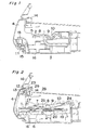
- Fig. 1 shows a disc loading apparatus in a state with a lid body closed and Fig. 2 shows a center portion thereof, while Fig. 3 shows a state when a clamper is raised, Fig. 4 shows a state with the lid body opened, and Fig. 5A shows a shape of the tray 1 while Fig. 5B shows a partial portion thereof.
- reference numeral 1 denotes a tray for carrying a disc 21 between a load starting position and a disc play position; 2 a first supporting part provided in one side of the tray 1; 3 a supporting part guide mechanism formed in the tray 1; 4 a lid body; and 5 a first engaging part provided in the lid body 4 for engaging with the first supporting part 2.
- Reference numeral 6 denotes a recording/reproducing mechanism; 7 a turntable of the recording/reproducing mechanism 6 for turning the disc 21; 8 a clamper for clamping the disc on the turntable; 9 a holding lever holding the clamper 8; and 10 a holding lever guide mechanism provided in the other side of the tray 1 opposite to the supporting part guide mechanism 3.
- Reference numeral 11 denotes a lid-opening spring for opening the lid body by its urging force; 15 a pinion; 16 a main body; 17 a second engaging part formed in the main body 16; 18 a gear provided on the main body 16; and 28 a printed wiring board.
- reference numeral 19 denotes a first disc guide part formed in a periphery of a first disc receiving recess formed in the tray 1 for matching in position a large sized disc with the recording/reproducing mechanism; 20 a second disc guide part formed in a periphery of a second disc receiving recess formed in the first disc receiving recess, where the center of the second disc guide part 20 is slightly shifted rearward with respect to the center of the first disc guide part 19, and 26 a disc-holding rib 26.
- Fig. 7 shows a state of the lid body when the lid body is opened
- Fig. 8 shows a locked state between the lid body and the main body 16 when an ejection button is not depressed
- Fig. 9 shows a state when the ejection button is depressed thereby to release the lid body from locking
- Fig. 10 shows a state when the ejection button is depressed thereby to start opening the lid body.
- reference numeral 12 denotes a lid lock lever; 13 an ejection button; 14 a switch; 22 a disc guide part formed in the lid body 4; 23 an ejection button stopper formed in the main body 16; 24 a lever spring urging the holding lever 9 upward; 25 a magnet held by the clamper 8; 26 a disc-holding rib in the second disc guide part 20; and 27 a rib provided at an upper inner side of the lid body 4 for turning ON the switch 14 when the lid is closed.
- the lid body 4 is held by the main body 16 in a pivotally rotatable manner and urged by an urging force of the lid-opening spring 11 toward the lid opening direction.
- the lid body 4 is provided with the lid-lock lever 12 which is engaged with the main body 16 to thereby hold the lid body 4 in the closed condition in stable.
- the lid body 4 is further provided with the ejection button 13 and when the lock lever 12 is depressed by pressing the ejection button 13, the closed condition of the lid body 4 is released.
- the lid body 4 has the pinion 15 provided thereon via a grease material which is filled in the space between the lid body 4 and the pinion 15.
- the pinion 15 is engaged with the gear 18 provided on the main body 16 so that the lid body is smoothly opened in the lid opening operation.
- the first engaging part 5 defined in the lid body 4 is engaged with the first supporting part 2 provided on the tray 1, so that the tray 1 is pivotally supported by the lid body 4 in a rotatable manner, while the supporting part guide mechanism 3 of the tray 1 is slidably engaged with the second engaging part 17 of the main body 16, so that the moving locus and posture of the tray 1 is appropriately regulated, maintaining a horizontal movement and stable mounting of the disc on the recording/reproducing mechanism.
- the tray 1 is provided with the first and second disc guide recessed parts 19 and 20 for securely holding the discs respectively on the constant positions on the tray.
- the first disc guide part 19 is formed as a first recess in the tray for positioning a larger sized disc thereon while the second disc guide part 20 is forced as a second recess defined in the first recess in a two-stepped manner for positioning a smaller one.
- the disc holding levels in the first and second recesses in height on the tray are different from each other as two stairs in the tray, so that the movement locus of the tray carrying the disc for loading and unloading is non-parallel to the extending direction of the rotary shaft of the turntable 7. Therefore, the center of the first disc guide part 19 is slightly shifted from the center of the second disc guide part 20.
- the lid body since the lid body is manually closed in a pivotal manner so that the tray associated with rotation of the lid body is horizontally moved, therefore when a smaller sized disc is carried in the position defined by the second recess 20, the disc may be detached from the second recess 20 due to changes in posture and vibrations of the tray when the disc is carried and mounted on the recording/reproducing mechanism 6, which may be a failure of correct loading of the disc.
- the tray has a pair of disc holding ribs 26 at right and left rear upper peripheral parts of the second disc guide part 20 as shown in Fig. 5B.
- the disc holding rib 26 has a flange shape for regulating the smaller sized disc by the upper periphery of the disc guide part 20.
- the clamper 8 securely clamps the disc 21 by the magnetic force of the magnet 25 when the disc is disposed on the turntable 7 of the recording/reproducing mechanism 6 and the clamper 8 is moved up and down in a circular arc locus by means of the clamper holding lever 9 which is rotatably held on the main body.
- the clamper holding lever 9 is moved downward by the regulation of the holding lever guide mechanism 10 provided on the tray 1 and is urged upward all the time by the lever spring 24, so that the clamper holding lever 9 is held up when the tray 1 is unlocked from the playing condition.
- the clamper 8 is pushed up by a part of the tray 1 or a part of the disc 21 on the tray.
- the first supporting part 2 of the tray 1 is pressed into the appliance interlockingly with the rotation of the lid body 4.
- the tray 1 moves tracing an outline of the supporting part guide mechanism 3 engaged with the second engaging part 17 of the main body 16.
- the supporting part guide mechanism 3 is a groove curved in a direction opposite to a locus of the first engaging part 5, in the initial stage of the operation, the tray 1 is pressed to move along a straight rear section of the supporting part guide mechanism 3, that is, almost in a horizontal direction.
- the tray In the latter half of the operation, in a recessed arc-like area of the supporting part guide mechanism 3, the tray retreats with a rear end thereof slightly raised due to a difference from a rotational locus of the lid body 4, and promptly descends after passing a critical point.
- the tray 1 assumes a locus approximate to the rotational locus of the lid body 4 while maintained in a generally horizontal state.
- the disc 21 on the tray 1 is moved by the disc guide part 22 of the lid body 4 shown in Fig. 7 to the rearward of the apparatus inside the first disc guide part 19 of the tray 1, whereby a shift of the disc from the center of the turntable is reduced.
- the disc 21 has a small diameter
- the disc is placed at the second disc guide part 20 of the tray 1 to be loaded to the recording/reproducing mechanism 6.
- the disc 21 is positionally regulated by the second disc guide part 20 shifted rearward of the apparatus, and accordingly the disc 21 is loaded to the turntable 7 of the recording/reproducing mechanism 6 without generating a positional shift in a front-and-rear direction.
- the clamper-holding lever 9 supported in a rotatable fashion to the main body 16 is pressed down by the holding lever guide 10 of the tray 1, thereby pushing and stably holding the disc 21 loaded to the turntable 7 of the recording/reproducing mechanism 6 by a magnetic force of the magnet 25 held by the clamper 8.
- the switch 14 is turned ON by the rib 27 formed in the lid body 4 and at the same time, the lid body 4 is locked by the lid lock lever 12.
- the disc 21 is thus set in a recordable/reproducible condition.
- the lid lock lever 12 When the ejection button 13 is pressed from a state of Fig. 8 wherein the ejection button is not pressed, the lid lock lever 12 is depressed, undergoing a state of Fig. 9 to release the locking, in a range before the ejection button 13 butts against the ejection button stopper 23 of the main body 16 in Fig. 10 and the lid body 4 is released.
- the lid body 4 starts to be opened by an opening force of the lid- opening spring 11. If the ejection button 13 is continuously pressed even after hitting the ejection button stopper 23 of the main body 16, the lid body 4 4 is opened to butt against the ejection button 13 by the opening force of the lid-opening spring 11. The ON state of the switch 14 by the lid body 4 is canceled at this moment, and simultaneously, the turntable 7 of the recording/reproducing mechanism 6 is braked thereby to attenuate the rotation of the rotating disc 21 to prevent the disc from slipping off from on the tray 1 when the lid body is opened. Then, the lid body 4 is opened at low speed without shocks owing to a damping effect by a highly viscous grease filled in a shaft part of the pinion 15 and by the opening force of the lid-opening spring 11.
- the disc-holding rib 26 formed in the second disc guide part 20 of Figs. 5A and 5B restricts the disc 21 not to stray from the disc guide part 20 in case the tray 1 oscillates or vibrates during the above loading/detaching operation.
- the members are constituted to interlock with each other primarily at the rotating time, the operation is reliably secured in the simple structure and the small moving amount allows the use of the spring to drive the apparatus and the loading apparatus is accordingly compact in size.
- the disc is never deviated from the guide part and not subject to shocks even when released from the clamper.
- the loading apparatus of the embodiment becomes simple, compact and high-quality, and operates with high reliability.
- Fig. 11 shows a loading apparatus according to a second embodiment of the present invention.
- Reference numerals 31 a shaft as a second supporting part set in the tray 1; and 30 a second engaging part at the side of the main body 16 which is an arc-shaped groove guided by the second supporting part 29 and curved in the same direction as and almost approximate to an arc-shaped locus of the first engaging part 5 of the lid body 4 because of the rotation of the lid body 4.
- the tray 1 traces/moves approximately the rotational locus of the first supporting part 2. Since a sliding resistance of the first and second engaging parts 5, 3C to the moving tray 1 works in the same direction because of the above locus, no unexpected force is applied to the tray 1, thus lightening the operation load.
- the supporting part guide mechanism provided in the tray is a shaft 31 while the second engaging part formed in the main body is an arc-shaped groove 30 guided by the shaft 31.
- the arc-shaped groove 30 curves in the same direction as and nearly approximate to the arc-shaped locus of the first engaging parr 5 defined by the rotation of the lid body.
- the loading apparatus of the embodiment achieves the smooth slide of the tray.
- the tray 1 carries the disc 21 between a disc loadable position where the disc can be loaded and a disc play position where the disc can be played for recording/reproducing operation.
- the lid body 4 is pivotally rotatable and is disposed in front of the recording and/or reproducing mechanism 6 in a main body 16 of the recording and/or reproducing apparatus in a generally vertical posture when in its closed state and in a generally horizontal posture when in its opened state.
- the tray 1 is guided, in association with one opening/closure of the lid body 4, between the loadable position when the lid body is in the open state and the play position when the lid body is in the closed state.
- the guide mechanism guides the tray so that the loadable position is located just above the lid body in its open state while the play position is located just above the recording and/or reproducing mechanism ; (6) where the disc is to be mounted thereon when the lid body is in the closed state.
- the guide mechanism is comprised of the first supporting part 2, supporting part guide mechanism 3 formed in the tray, first engaging part 5 formed in the lid body for engaging with the first supporting part 2 in a freely rotatable fashion, thereby interlocking the tray with the rotation of the lid body.
- the guide mechanism further includes the second engaging part 17 integrally formed with the main body, which guides the supporting part guide mechanism 3 in a slidably movable fashion.
- the second engaging part 17 and the supporting part guide mechanism 3 are held in such a relation of relative movement as to regulate the movement of the tray in an arc-shaped locus in correspondence to a locus of the first engaging part 5 and the first supporting part 2 in accordance with the rotation of the lid body while maintaining the tray in a substantially horizontal posture to load the disc on the recording/reproducing mechanism.
- the tray can be transferred while being controlled to keep one substantially horizontal posture to be located between the loadable position just above the lid body for loading the disc when the lid body is in the open state and the play position where the disc is mounted on the recording/reproducing mechanism to be played when the lid is in the closed condition.
- the supporting part guide mechanism 3 provided in the tray 1 includes a generally arc-shaped groove portion in its frontward and a straight extending groove portion in its rearward, while the second engaging part 17 integrally formed with the main body is a shaft engaged in the groove guide 3 thereby to be guided by the sliding movement thereof.
- the arc-shaped groove portion curves in an opposite direction, i.e., having a reverse curvature to the arc-shaped locus of the first engaging part 5 defined by the rotation of the lid body 4.
- the supporting part guide mechanism provided in the tray is a shaft 31 while the second engaging part formed in the main body is an arc-shaped groove 30 to be guided by the shaft 29.
- the arc-shaped groove 30 curves in the same direction, i.e., having nearly the same curvature as that of and nearly approximate to the arc-shaped locus of the first engaging part 5 defined by the rotation of the lid body.
- a disc is used as a recording medium, and a turntable 7 is disposed horizontally for a disc reproducing mechanism 6 in a disc reproducing apparatus.
- the tray carries the disc thereon, thereby moving the disc from a loadable position to a reproducible position.
- the lid body 4 is pivorally openable and is constituted in a main body nearly in front of the disc reproducing mechanism and disposed in an almost vertical posture when the lid is in the closed state.
- the tray is moved by guide means from the loadable position to the reproducible position in association with the opening/closure of the lid body, and the clamper-holding lever 9 for holding the clamper which securely presses the disc onto the turnable at the reproducible position when in the lid closed condition.
- the clamper-holding lever 9 is pivotally supported to the main body in a freely movable fashion in a vertical direction in association with the movement of the tray.
- the guide means is so constituted as to position the tray over the lid body to load the disc when the lid is open and bring the tray to a position where the disc is placed over the recording/reproducing mechanism to be recorded/reproduced when the lid is closed. In association with the transfer of the disc, the disc loaded to the reproducible position can be held stably on the tray.
- the tray is associated with the lid body which is rotatable in opening and closing operation so that the disc is carried by the tray in a non-linear locus to be mounted on the recording and/or reproducing mechanism.
- the clamper In this construction using, e.g., a CD, in order to playback the disc in the recording and/or reproducing mechanism, the disc is needed to be clamped onto the turntable of the recording and/or reproducing mechanism by means of the clamper, the clamper is associated with the movement of the tray by means of the clamper holding lever 9 and the holding lever guide mechanism 10.
- the clamping of the clamper is to be unlocked. Therefore, in the clamp releasing mechanism using an urging force by a spring, the force by the spring urging the tray upward is all the time active also during the disc playing condition.
- the gap between the disc and the tray is possibly reduced due to changes in time lapse or difference in spring forces, rubbing against each other, resulting in causing an erroneous playback or undesirable reproduction by a damage or the like.
- the clamper pressing the disc is pushed up by a disc loading face of an upper face of the tray or an upper face of the disc on the tray, so that the disc is released from clamping. Therefore, the clamper can be separated from the turntable with a small load without shocks.
- the disc when the lid body is opened during the disc playing operation, the disc is forced to be raised up from the turntable of the recording and/or reproducing mechanism prior to the stop of the rotation of the disc. Therefore, the disc may be rotated in the tray by its rotational inertia, resulting in removal from a disc regulation recess (19, 20) formed in the tray or damaging the recording and/or reproducing surface of the disc, causing an erroneous reproduction.
- the lid body 4 is provided with a projection such as a rib 27 and a switch 14 attached to a printed wiring board 28 fixed inside the main body, so that it is electrically detected only when the lid body is closed, thereby to supply electric power to the recording/reproducing mechanism. Otherwise, the recording/reproducing mechanism is accordingly effectively refrained from operating when the lid is opened. Meanwhile, it is detected that the lid body is opened when the lid body is forcibly opened during the reproduction operation, and the turntable of the recording/reproducing mechanism is braked to attenuate the rotation of the rotating disc, whereby the disc is prevented from slipping off from the tray when the lid is opened.
- the lid body is provided with an ejection button 13 for unlocking the lid body, so that the lock of the lid body is released by depressing the ejection button 13.
- the lid body is pushed toward the main body 16 due to the reaction of the restoring force of the ejection button, and when the depressing of the ejection button is released, the lid body is started to be opened.
- the ejection button may be restored and the lid body lock lever 12 being operated by the ejection button is restored prior to the opening of the lid body, and therefore the lock of the lid body can not be released in some cases.
- the lock lever hook 12 is unlocked in a range before the ejection button 13 butts against a stopper 23 formed in the main body, with a gap defined between the lid body and the ejection button so that the lid body and the lock lever hook are opened by a lid-opening force to butt against the ejection button after the ejection button butts against the stopper.
- the lid body is prevented from being locked again by the returning lock lever 12 when the load applied to the ejection button is removed.
- the lid body is provided with the guide part 22 for regulating the movement of the disc carried on the tray to the rearward of the apparatus within a range of the disc guide part on the tray when the lid body is closed, to thereby correct a displacement of the disc from the center of the turntable of the recording and/or reproducing mechanism when the disc is loaded and/or separated to/from the turntable.
- the disc can be loaded and/or unloaded smoothly, improving the accuracy in loading and detaching the disc on and from the recording/reproducing mechanism.
- the depth of the disc guide recessed part is made equal to or slightly larger than the thickness of the disc and a flange-like rib 26 is formed at an upper part of the disc guide recessed part of the tray, so that the disc carried on the tray is prevented from slipping out of the disc guide recessed part during the loading operation.
- the present invention provides the loading apparatus for recording media in a recording/reproducing apparatus having the horizontally arranged recording/reproducing mechanism. More specifically, the loading apparatus of the invention includes the tray for carrying the recording medium thereon thereby to move the recording medium from the loadable position to the recordable/reproducible position, the lid body arranged in a generally vertical posture in the closed state thereof and constituted in the main body nearly in front of the recording/reproducing mechanism, and includes the guide means for moving the tray between the loadable position and the recordable/reproducible position.
- the guide means is so constituted as to position the tray, in association with the opening/closure of the lid body, over the lid body to load the recording medium when the lid is open and bring the tray to a position where the recording medium is placed on the recording/reproducing mechanism to be recorded/reproduced when the lid is closed. Therefore, the loading apparatus becomes simple, compact and high-quality and operates with high reliability.
Landscapes
- Feeding And Guiding Record Carriers (AREA)
- Holding Or Fastening Of Disk On Rotational Shaft (AREA)
Claims (11)
- Ladevorrichtung zum Laden eines Aufzeichnungsmediums, welches in einem Aufzeichnungs- und/oder Wiedergabegerät verwendet wird, das einen horizontal angeordneten Aufzeichnungs- und/oder Wiedergabemechanismus (6) besitzt, enthaltend:dadurch gekennzeichnet, daß der Führungsmechanismus (2, 5, 3, 17; 29, 30) ein zweites Eingriffsteil (17) aufweist, welches einstückig mit dem Hauptkörper ausgebildet ist und ein zweites Halteteil (3) in einer gleitenden Bewegung führt, wobei das zweite Eingriffsteil (17) und das zweite Halteteil (3) in einer solchen Relativbewegungsbeziehung gehalten sind, daß der Teller in einer bogenförmigen Ortskurve in Übereinstimmung mit einer Ortskurve des ersten Eingriffsteils (5) und des ersten Halteteils (2) nach der Drehung des Klappenkörpers geführt wird, während der Teller in einer im wesentlichen horizontalen Stellung gehalten wird, um das Aufzeichnungsmedium auf den Aufzeichnungs- und Wiedergabemechanismus (6) zu laden.einen Teller (1) zum Tragen des darauf angeordneten Aufzeichnungsmediums (21), wobei das Aufzeichnungsmedium zwischen einer Ladeposition, in der das Aufzeichnungsmedium geladen wird, und einer Abspielposition bewegbar ist, in der das Aufzeichnungsmedium für den Aufzeichnungs- und/oder Wiedergabevorgang abgespielt wird,einen drehbaren Klappenkörper (4), welcher in einem Hauptkörper (16) des Aufzeichnungs- und Wiedergabegerätes vor dem Aufzeichnungs- und/oder Wiedergabemechanismus (6) in einer im wesentlichen vertikalen Ausrichtung angeordnet ist, wenn er sich in seinem geschlossenen Zustand befindet, und in einer im wesentlichen horizontalen Ausrichtung angeordnet ist, wenn er sich in seinem geöffneten Zustand befindet, undeinen Führungsmechanismus (2, 5, 3, 17; 29, 30), um den Teller in Verbindung mit dem Öffnen/Schließen des Klappenkörpers zwischen der Ladeposition, wenn sich der Klappenkörper im geöffneten Zustand befindet, und der Abspielposition zu führen, wenn sich der Klappenkörper in der geschlossenen Position befindet,wobei der Führungsmechanismus (2, 5, 3, 17; 29, 30) den Teller so führt, daß sich die Ladeposition gerade oberhalb des Klappenkörpers bei geöffnetem Klappenkörper befindet, während sich die Abspielposition gerade oberhalb des Aufzeichnungs- und/oder Wiedergabemechanismus (6) befindet, auf dem das Aufzeichnungsmedium anzubringen ist,wobei der Führungsmechanismus (2, 5, 3, 17; 29, 30) ein erstes, auf dem Teller ausgebildetes Halteteil (2, 3) und ein erstes Eingriffsteil (5) aufweist, das in dem Klappenkörper für den Eingriff mit dem ersten Halteteil (2) in einer schwenk- und drehbaren Weise ausgebildet ist, um dadurch den Teller mit der Drehung des Klappenkörpers zu verriegeln,
- Ladevorrichtung nach Anspruch 1,
bei der das zweite Halteteil (3) des Tellers eine im wesentlichen bogenförmige Nut ist, während das zweite Eingriffsteil (17) des Hauptkörpers ein Schaft ist, welcher in Eingriff mit der Nut steht, um dadurch in einer Gleitbewegung geführt zu werden,
dadurch gekennzeichnet, daß sich die bogenförmige Nut (3) in eine Richtung entgegengesetzt zu der bogenförmigen Ortskurve des ersten Eingriffsteils (5) krümmt, die durch die Drehung des Klappenkörpers definiert ist. - Ladevorrichtung nach Anspruch 1,
bei der das zweite Halteteil des Tellers ein Schaft (19) ist, während das zweite Eingriffsteil, das in dem Hauptkörper ausgebildet ist, eine bogenförmige Nut (30) ist, die durch die Welle (29) geführt ist,
dadurch gekennzeichnet, daß sich die bogenförmige Nut (30) in die gleiche Richtung wie die bogenförmige Ortskurve und nahezu neben der bogenförmigen Ortskurve des ersten Eingriffsteils (5) krümmt, die durch die Drehung des Klappenkörpers definiert ist. - Ladevorrichtung nach einem der vorstehenden Ansprüche,
dadurch gekennzeichnet, daß das Aufzeichnungsmedium eine Disk ist, die in einem Diskwiedergabegerät verwendet wird, welches einen Drehteller (7) enthält, der horizontal für einen Diskwiedergabemechanismus (6) angeordnet ist. - Ladevorrichtung nach Anspruch 4,
weiterhin enthaltend: eine Klemmeinrichtung (8), die die Disk auf dem Drehteller (7) in der Diskabspielposition sicher festklemmt, und einen Klemmhaltehebel (9) zum Halten der Klemmeinrichtung (8), welcher schwenkbar an dem Hauptkörper gehalten ist und in Verbindung mit der Bewegung des Tellers in eine vertikale Richtung bewegbar ist. - Ladevorrichtung nach Anspruch 5,
bei der die Klemmeinrichtung (8), die die Disk festhält, durch eine Diskladefläche der Oberseite des Tellers (1) nach oben gedrückt wird, wenn der Teller (1) in die Diskladeposition bewegt wird, wodurch die Disk auf dem Teller (1) aus dem Klemmzustand freigegeben wird. - Ladevorrichtung nach Anspruch 5,
bei der der Klappenkörper mit einem Vorsprung (27) und einem Schalter (14) versehen ist, der an einer gedruckten Schaltungsplatine (28) angebracht ist, die innerhalb des Hauptkörpers befestigt ist, um elektrisch den Schließzustand des Klappenkörpers zu erfassen, so daß elektrische Energie dem Diskwiedergabemechanismus (6) zum Abspielen der Disk zugeführt wird, während, wenn der Klappenkörper gewaltsam während des Wiedergabebetriebes geöffnet wird, der Öffnungszustand des Klappenkörpers elektrisch erfaßt wird, wodurch der Drehteller des Diskwiedergabemechanismus gebremst wird, um die Drehung der sich drehenden Disk zu verlangsamen. - Ladevorrichtung nach Anspruch 1 oder 4,
bei der der Klappenkörper einen Ausstoßknopf (13) und einen Verriegelungshebel (12) aufweist, welcher in einem Bereich entriegelt ist, bevor der Ausstoßknopf gegen einen Anschlag (23) stößt, der in dem Hauptkörper ausgebildet ist,
dadurch gekennzeichnet, daß eine Lücke zwischen dem Klappenkörper (4) und dem Ausstoßknopf (13) so definiert ist, daß der Klappenkörper und der Verriegelungshebel durch eine Klappenöffnungskraft geöffnet wird, um gegen den Ausstoßknopf zu stoßen, nachdem der Ausstoßknopf gegen den Anschlag (23) stößt. - Ladevorrichtung nach Anspruch 4,
bei der der Teller einen ersten kreisförmigen, abgesetzten Teil (19) aufweist, um eine großformatige Disk aufzunehmen, wobei der Mittelpunkt des ersten, abgesetzten Teils (19) vom Mittelpunkt des Drehtellers aus nach hinten versetzt ist. - Ladevorrichtung nach Anspruch 9,
bei der der Klappenkörper mit einem Führungsteil (22) versehen ist, um eine auf dem Teller liegende Disk innerhalb des Bereiches des ersten in dem Teller ausgebildeten abgesetzten Teiles im Gerät nach hinten zu bewegen, wenn der Klappenkörper geschlossen wird. - Ladevorrichtung nach Anspruch 4,
bei der der Teller einen zweiten kreisförmigen abgesetzten Teil (20) aufweist, welcher zur Aufnahme einer kleinformatigen Disk ausgebildet ist und welcher eine flanschartige Rippe (26) aufweist, die an seinem oberen Umfang ausgebildet ist.
Applications Claiming Priority (3)
| Application Number | Priority Date | Filing Date | Title |
|---|---|---|---|
| JP09826296A JP3216521B2 (ja) | 1996-04-19 | 1996-04-19 | ローディング装置 |
| JP9826296 | 1996-04-19 | ||
| JP98262/96 | 1996-04-19 |
Publications (3)
| Publication Number | Publication Date |
|---|---|
| EP0802534A2 EP0802534A2 (de) | 1997-10-22 |
| EP0802534A3 EP0802534A3 (de) | 1998-03-25 |
| EP0802534B1 true EP0802534B1 (de) | 2000-02-02 |
Family
ID=14215043
Family Applications (1)
| Application Number | Title | Priority Date | Filing Date |
|---|---|---|---|
| EP97106493A Expired - Lifetime EP0802534B1 (de) | 1996-04-19 | 1997-04-18 | Lademechanismus zum Laden eines Informationsträgers in ein Aufzeichnungs-/Wiedergabegerät |
Country Status (5)
| Country | Link |
|---|---|
| US (1) | US6028832A (de) |
| EP (1) | EP0802534B1 (de) |
| JP (1) | JP3216521B2 (de) |
| DE (1) | DE69701238T2 (de) |
| MY (1) | MY119427A (de) |
Families Citing this family (13)
| Publication number | Priority date | Publication date | Assignee | Title |
|---|---|---|---|---|
| CA2232078C (en) * | 1997-03-14 | 2004-05-25 | Sanyo Electric Co., Ltd. | Disk playback device |
| JP3437499B2 (ja) * | 1999-08-06 | 2003-08-18 | 日本マランツ株式会社 | 記録媒体の再生装置 |
| EP1288940B1 (de) * | 2000-05-22 | 2009-12-02 | Clarion Co., Ltd. | Plattenspieler |
| TW594691B (en) * | 2002-06-25 | 2004-06-21 | Benq Corp | Disc apparatus with device for preventing a cracked disc shooting out |
| KR100464422B1 (ko) * | 2002-07-03 | 2005-01-03 | 삼성전자주식회사 | 도어잠금수단을 갖는 디스크 드라이브의 프런트 패널조립체 및 이를 구비한 디스크 드라이브 |
| EP1416483A1 (de) * | 2002-11-04 | 2004-05-06 | Elitegroup Computer Systems Co.,Ltd. | Plattenauswurfvorrichtung eines tragbaren Rechners und Verfahren zur Steuerung des Plattenauswurfs |
| TWI229847B (en) * | 2004-02-25 | 2005-03-21 | Lite On It Corp | Flipper |
| CN2706832Y (zh) * | 2004-04-22 | 2005-06-29 | 鸿富锦精密工业(深圳)有限公司 | 数据存取机防尘装置 |
| JP3912684B2 (ja) * | 2004-07-06 | 2007-05-09 | ソニー株式会社 | ディスクドライブ装置 |
| KR100598018B1 (ko) | 2004-07-24 | 2006-07-13 | 삼성전자주식회사 | 도어안전장치 및 그것을 갖는 디스크 기록/재생장치 |
| JP2006221735A (ja) * | 2005-02-10 | 2006-08-24 | Orion Denki Kk | トレイを備えた記録再生装置 |
| DE102005021338A1 (de) * | 2005-05-04 | 2006-11-09 | Deutsche Thomson-Brandt Gmbh | Lademechanismus zum Laden eines auswechselbaren scheibenförmigen Speichermediums in ein Gehäuse |
| CN2874611Y (zh) * | 2005-12-30 | 2007-02-28 | 鸿富锦精密工业(深圳)有限公司 | 电脑面板 |
Family Cites Families (16)
| Publication number | Priority date | Publication date | Assignee | Title |
|---|---|---|---|---|
| US3899794A (en) * | 1973-11-30 | 1975-08-12 | Wangco Inc | Front loading disc drive apparatus |
| NL173696C (nl) * | 1975-09-11 | 1984-02-16 | Philips Nv | Optische platenspeler. |
| JPS5613562A (en) * | 1979-07-13 | 1981-02-09 | Toshiba Corp | Equipping unit for magnetic disk cartridge |
| JPS58122641A (ja) * | 1982-01-18 | 1983-07-21 | Pioneer Electronic Corp | フロントロ−デイングレコ−ドプレ−ヤ |
| JPS6186851U (de) * | 1984-11-13 | 1986-06-06 | ||
| US4669076A (en) * | 1985-10-30 | 1987-05-26 | International Business Machines Corporation | Optical disk drive apparatus with means for accurate disk positioning |
| AT384688B (de) * | 1986-03-07 | 1987-12-28 | Philips Nv | Aufzeichnungs- und/oder wiedergabegeraet mit einem zum aufnehmen eines aufzeichnungstraegers vorgesehenen aufnahmeraum |
| JPH0525006Y2 (de) * | 1987-12-18 | 1993-06-24 | ||
| JP2808309B2 (ja) * | 1989-07-07 | 1998-10-08 | 旭光学工業株式会社 | ディスク駆動装置 |
| JP3179458B2 (ja) * | 1989-07-07 | 2001-06-25 | ソニー株式会社 | 光磁気ディスク装置 |
| US5341357A (en) * | 1990-12-21 | 1994-08-23 | Sony Corporation | Optical disc recording apparatus |
| KR100262791B1 (ko) * | 1991-08-21 | 2000-08-01 | 이데이 노부유끼 | 디스크 구동 장치용 디스크 로딩 기구 |
| US5457677A (en) * | 1991-09-27 | 1995-10-10 | Pioneer Electronic Corporation | Adapter for a small CD |
| KR950012235B1 (ko) * | 1993-07-28 | 1995-10-16 | 대우전자주식회사 | 미니디스크 플레이어의 디스크 로딩장치 |
| JPH07249250A (ja) * | 1994-03-09 | 1995-09-26 | Matsushita Electric Ind Co Ltd | ディスクローディング装置 |
| JP3041659U (ja) | 1997-03-19 | 1997-09-22 | わかばプランニング株式会社 | メールオーダー封筒セット |
-
1996
- 1996-04-19 JP JP09826296A patent/JP3216521B2/ja not_active Expired - Fee Related
-
1997
- 1997-04-18 US US08/837,465 patent/US6028832A/en not_active Expired - Lifetime
- 1997-04-18 EP EP97106493A patent/EP0802534B1/de not_active Expired - Lifetime
- 1997-04-18 DE DE69701238T patent/DE69701238T2/de not_active Expired - Fee Related
- 1997-04-19 MY MYPI97001702A patent/MY119427A/en unknown
Also Published As
| Publication number | Publication date |
|---|---|
| MY119427A (en) | 2005-05-31 |
| DE69701238T2 (de) | 2000-09-28 |
| JPH09288855A (ja) | 1997-11-04 |
| EP0802534A3 (de) | 1998-03-25 |
| DE69701238D1 (de) | 2000-03-09 |
| EP0802534A2 (de) | 1997-10-22 |
| US6028832A (en) | 2000-02-22 |
| JP3216521B2 (ja) | 2001-10-09 |
Similar Documents
| Publication | Publication Date | Title |
|---|---|---|
| US5301176A (en) | Apparatus for carrying out recording and/or reproducing signals for disk-shaped recording medium | |
| JP3533681B2 (ja) | カートリッジのイジェクト機構 | |
| EP0802534B1 (de) | Lademechanismus zum Laden eines Informationsträgers in ein Aufzeichnungs-/Wiedergabegerät | |
| JPH10208359A (ja) | 電子機器 | |
| JP3595682B2 (ja) | ディスク装置 | |
| US6208607B1 (en) | Disk loading apparatus with interlocked shutter mechanism, elevator mechanism and eject mechanism | |
| US6782547B1 (en) | Disk drive with slider pressure plate | |
| JP4322873B2 (ja) | スロットイン型ディスク装置 | |
| US6560186B2 (en) | Apparatus and method with a driving mechanism for opening a shutter of a cartridge | |
| JP3593417B2 (ja) | 情報記録ディスクの記録再生装置 | |
| EP0944067B1 (de) | Plattenspieler | |
| US6385155B1 (en) | Positioning system for use in an information recording/reproducing apparatus | |
| JPH054156Y2 (de) | ||
| KR0122990Y1 (ko) | 테이프 레코더의 데크 이젝트 장치 | |
| JP3812317B2 (ja) | カートリッジ装着装置 | |
| JP3594408B2 (ja) | 情報記録ディスクの記録再生装置 | |
| JP2000021067A (ja) | ディスク装置 | |
| JPH051006Y2 (de) | ||
| JP3728979B2 (ja) | 記録媒体装着装置 | |
| JP2007200377A (ja) | スロットイン型ディスク装置 | |
| JP4331163B2 (ja) | スロットイン型ディスク装置 | |
| KR100194331B1 (ko) | 광디스크 로딩장치 | |
| JP3746118B2 (ja) | カートリッジのローディング機構 | |
| JPH09265721A (ja) | ディスクドライブ装置 | |
| JPH10106099A (ja) | ディスク着脱装置およびディスクプレーヤ |
Legal Events
| Date | Code | Title | Description |
|---|---|---|---|
| PUAI | Public reference made under article 153(3) epc to a published international application that has entered the european phase |
Free format text: ORIGINAL CODE: 0009012 |
|
| 17P | Request for examination filed |
Effective date: 19970418 |
|
| AK | Designated contracting states |
Kind code of ref document: A2 Designated state(s): DE GB |
|
| PUAL | Search report despatched |
Free format text: ORIGINAL CODE: 0009013 |
|
| AK | Designated contracting states |
Kind code of ref document: A3 Designated state(s): DE GB |
|
| 17Q | First examination report despatched |
Effective date: 19980918 |
|
| GRAG | Despatch of communication of intention to grant |
Free format text: ORIGINAL CODE: EPIDOS AGRA |
|
| GRAG | Despatch of communication of intention to grant |
Free format text: ORIGINAL CODE: EPIDOS AGRA |
|
| GRAH | Despatch of communication of intention to grant a patent |
Free format text: ORIGINAL CODE: EPIDOS IGRA |
|
| GRAH | Despatch of communication of intention to grant a patent |
Free format text: ORIGINAL CODE: EPIDOS IGRA |
|
| GRAA | (expected) grant |
Free format text: ORIGINAL CODE: 0009210 |
|
| AK | Designated contracting states |
Kind code of ref document: B1 Designated state(s): DE GB |
|
| REF | Corresponds to: |
Ref document number: 69701238 Country of ref document: DE Date of ref document: 20000309 |
|
| PLBE | No opposition filed within time limit |
Free format text: ORIGINAL CODE: 0009261 |
|
| STAA | Information on the status of an ep patent application or granted ep patent |
Free format text: STATUS: NO OPPOSITION FILED WITHIN TIME LIMIT |
|
| 26N | No opposition filed | ||
| REG | Reference to a national code |
Ref country code: GB Ref legal event code: IF02 |
|
| PGFP | Annual fee paid to national office [announced via postgrant information from national office to epo] |
Ref country code: GB Payment date: 20050413 Year of fee payment: 9 |
|
| PGFP | Annual fee paid to national office [announced via postgrant information from national office to epo] |
Ref country code: DE Payment date: 20050414 Year of fee payment: 9 |
|
| PG25 | Lapsed in a contracting state [announced via postgrant information from national office to epo] |
Ref country code: GB Free format text: LAPSE BECAUSE OF NON-PAYMENT OF DUE FEES Effective date: 20060418 |
|
| PG25 | Lapsed in a contracting state [announced via postgrant information from national office to epo] |
Ref country code: DE Free format text: LAPSE BECAUSE OF NON-PAYMENT OF DUE FEES Effective date: 20061101 |
|
| GBPC | Gb: european patent ceased through non-payment of renewal fee |
Effective date: 20060418 |