EP0802150B1 - Verfahren und Anlage zur Lageregelung einer gehobenen Last mittels eines Gyroskops - Google Patents
Verfahren und Anlage zur Lageregelung einer gehobenen Last mittels eines Gyroskops Download PDFInfo
- Publication number
- EP0802150B1 EP0802150B1 EP19960302779 EP96302779A EP0802150B1 EP 0802150 B1 EP0802150 B1 EP 0802150B1 EP 19960302779 EP19960302779 EP 19960302779 EP 96302779 A EP96302779 A EP 96302779A EP 0802150 B1 EP0802150 B1 EP 0802150B1
- Authority
- EP
- European Patent Office
- Prior art keywords
- gimbal
- frame
- lifting load
- driving portion
- resetting
- Prior art date
- Legal status (The legal status is an assumption and is not a legal conclusion. Google has not performed a legal analysis and makes no representation as to the accuracy of the status listed.)
- Expired - Lifetime
Links
- 230000000694 effects Effects 0.000 title claims description 16
- 238000000034 method Methods 0.000 title claims description 5
- 238000009987 spinning Methods 0.000 claims description 29
- 230000002441 reversible effect Effects 0.000 claims description 8
- 230000005540 biological transmission Effects 0.000 description 7
- 238000010276 construction Methods 0.000 description 2
- 229910000831 Steel Inorganic materials 0.000 description 1
- 230000001133 acceleration Effects 0.000 description 1
- 210000000078 claw Anatomy 0.000 description 1
- 239000010959 steel Substances 0.000 description 1
Images

Classifications
-
- B—PERFORMING OPERATIONS; TRANSPORTING
- B66—HOISTING; LIFTING; HAULING
- B66C—CRANES; LOAD-ENGAGING ELEMENTS OR DEVICES FOR CRANES, CAPSTANS, WINCHES, OR TACKLES
- B66C13/00—Other constructional features or details
- B66C13/04—Auxiliary devices for controlling movements of suspended loads, or preventing cable slack
- B66C13/08—Auxiliary devices for controlling movements of suspended loads, or preventing cable slack for depositing loads in desired attitudes or positions
Definitions
- the present invention relates to a method and a system for controlling attitude of a lifting load for appropriately pivoting a lifting load lifted by means of a wire rope or so forth. More specifically, the invention relates to a system which carries a gyro on a lifting jig for lifting the lifting load in horizontal attitude by means of the wire rope or so forth and obtaining a horizontal rotating force of the lifting jig in the horizontal direction utilizing a gyro effect.
- the rotating attitude controlling system for the lifting load disclosed in the above-identified publication is formed with a lifting jig which is hanged in horizontal attitude on a wire rope and mounting a lifting load at the lower portion thereof, a frame fixed on the lifting jig, and a case rotatable about a rotation axis parallel to an extending direction relative to the frame, and a flywheel capable of spinning shaft perpendicular to a surface including a rotation axis of the case.
- the case and the flywheel form a gimbal structure to form pseudo gyro scope together with the frame.
- the lifting load is pivoted in the opposite direction in a magnitude corresponding to the natural rotation by driving the gymbal by a motor, while the natural rotation angle is relatively small, for constantly maintaining predetermined azimuth angle.
- the offset position is the rotational position of the gimbal when the driving motor of the gimbal is not actuated and the gimbal is not locked.
- initial position a initial position
- rotation in the direction of external disturbance is accelerated. While such pre-session force is convenient if pivots the lifting load in the same direction to the rotating direction by the external disturbance, when a rotational force in opposite direction is to be applied, it becomes necessary to return to the initial position by tilting the gimbal to exert the pivoting force on the lifting load in the same direction to the rotating direction by the external disturbance.
- US-A-3608384 discloses an apparatus for selectively horizontally orienting a freely swiveled cargo load, and for maintaining a desired horizontal position, employs a rotating flywheel attached to a load bearing platform by a mounting gimbal. Apparatus is provided to selectively rotate the spinning flywheel about a horizontal axis disposed along a diameter of the flywheel, thereby applying a torque in a desired direction about the vertical axis of the gimbal, platform and load. Thus, the load may be rotated in a horizontal plane to any desired orientation and, moreover, maintained in that position.
- the present invention is worked out in view of the problems in the prior art. Therefore, it is an object of the present invention to provide a method and system for controlling a lifting load which can easily return a gimbal which is rotated by external disturbance, to a initial position utilizing a gyro effect without influencing pivoting motion of the lifting load.
- a lifting load attitude control system utilizing a gyro effect comprises:
- the lifting load pivoting clutch is placed in engaged or connected position.
- the gimbal When external disturbance, such as wind or so forth is exerted on the lifting load for causing pivoting motion about the pivoting axis, the gimbal is rotated to place the spinning shaft of the flywheel at the orientation close to vertical depending upon the magnitude of the externally applied disturbing force. Thereafter, when the gimbal is returned to the initial position, the lifting load pivoting clutch is placed in disengaged condition and the rotational driving portion is driven in reverse direction. Then, the gimbal rotates obliquely. At this time, since the flywheel is held rotating, gyro effect is caused to rotation of the gimbal frame in the same direction.
- the gimbal frame and the gyro frame are spaced away from each other, the gimbal may solely rotated without influencing to the gyro frame. Accordingly, the gimbal may be returned to the initial position without exerting pivoting force to the lifting load in the same direction.
- the resetting obliquely rotating clutch In the normal rotating operation, in addition to maintaining of the lifting load pivoting clutch in the engaged condition, the resetting obliquely rotating clutch is placed in the disengaged position. Upon oblique rotation for returning the gimbal to the initial position, the resetting obliquely rotating clutch is placed in engaged position and the lifting load pivoting clutch is placed in disengaged position.
- the resetting oblique rotation driving portion is driven at this position, similarly to the first aspect of the invention, the gimbal may be rotated without exerting pivoting force for the lifting load.
- the lifting load attitude control system further comprises a variable constant torque transmitting device provided between the gyro frame and the gimbal frame.
- the gimbal frame Upon obliquely rotating the gimbal to return to the initial position, the gimbal frame is rotated by gyro effect. Then, only relatively small torque set by the variable constant torque transmission device is transmitted to the gyro frame. The gimbal can be quickly returned to the initial position with little influence for gyro frame and thus the lifting jig (lifting load). At this time, As a reaction field of the inertia moment of the lifting load, small transmission torque between the gyro frame and the gimbal frame serves as a force for braking rotation of the gimbal frame.
- a method for controlling pivoting motion of a lifting load hanged by a lifting jig employing a lifting load attitude control system as set forth above comprises the steps of:
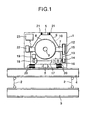
- Figs. 1 and 2 show a lifting load attitude controlling system utilizing a gyro effect according to the present invention.
- the shown lifting load attitude controlling system includes a box shaped gyro frame 1 hanged by a crane (not shown), a lifting jig 4 formed with wide flange beam or H steel for hanging down a lifting load 3 (wide flange beam in the shown case) with hanging ropes 2, 2 fixedly integrated in the horizontal condition on the bottom portion of the gyro frame 1, a gimbal frame 6 rotatable about a vertical rotation axis 5 within the gyro frame 1, a gimbal 8 rotatable about a rotation shaft 7 with respect to the gimbal frame 6, and a flywheel 10 which can spin about a spinning shaft 9 with respect to the gimbal 8.
- the gimbal 8 is rotatable at appropriate speed in forward and reverse directions about the rotation axis 7 (axis parallel to the lifting jig 4) perpendicular to a surface including a rotation axis 5 of the gimbal frame 6 by means of a gimbal driving motor 11 (rotary driving portion) mounted on the gimbal frame 6.
- the flywheel 10 can spin at high speed about the spinning shaft 9 perpendicular to the surface including the rotation shaft 7 of the gimbal 8 by a not shown spinning motor (spin driving portion) mounted on the gimbal.
- the gimbal driving motor 11 and the spinning motor are electromagnetic motors driving for rotation and spinning of the rotation shaft 7 and the spinning shaft 9 in non-contact state, respectively.
- a driven pulley 12 is connected to one end of the rotation shaft 7 of the gimbal 8.
- a driving pulley 14 is connected to one end of a rotary driving shaft 13 arranged in parallel to the rotation shaft 7. Between both pulleys 12 and 14, a timing belt 15 is wound around.
- a rotational driving force of the gimbal driving motor 11 is transmitted to the rotary driving shaft 13 via a helical gear box 16.
- the other end of the rotary driving shaft 13 is releasably connected to a resetting obliquely rotating motor 19 (resetting obliquely rotating driving portion) via a resetting obliquely rotating clutch 17 (electromagnetic clutch) and a speed reduction mechanism 18.
- the gimbal driving motor 11 can drive to rotate the rotary driving shaft 13 in forward and reverse directions in non-contact condition.
- a warm gear mechanism 18 has non-reversible characteristics for permitting transmission of a driving force from the setting obliquely rotating motor 19 to the rotary driving shaft 13 but prohibiting transmission of driving force from the rotary driving shaft 13 to the resetting oblique rotating motor 19.
- the resetting obliquely rotating clutch 17 is placed in released condition, the rotational driving force of the gimbal driving motor 11 is transmitted to the rotating driving shaft 13 and then transmitted to the rotation shaft 7 of the gimbal 8 via the driving pulley 14, the timing belt 15 and driven pulley 12 in order.
- the resetting obliquely rotating clutch 17 is placed in engaged condition, obliquely rotating driving force of the resetting obliquely rotating motor 19 is transmitted to the rotary driving shaft 13 and then transmitted to the rotation shaft 7 of the gimbal 8. Accordingly, the gimbal driving motor 11 drives the gimbal 8 in forward and reverse directions, whereas the resetting obliquely rotating motor 19 is adapted to drive the gimbal obliquely upon returning to the initial position.
- the resetting obliquely rotating clutch may be directly connected to the gimbal via the driven pulley 12 instead of connecting to the resetting obliquely rotating motor 19.
- a lifting road rotating clutch 20 for contacting and releasing the surfaces.
- the lifting load pivoting clutch 20 is placed in connecting condition, the gimbal frame 6 rotates integrally with the gyro frame 1, namely the lifting jig 4 (lifting load 3).
- the lifting load pivoting clutch 20 is released, even when rotation of the gimbal 8 is transmitted to the gimbal frame 6, the transmitted rotation force will never influence to the lifting jig 4 (lifting load).
- variable constant torque transmitting device 21 is provided between the lower surface of a ceiling portion of the gyro frame 1 and the upper surface of the ceiling portion of the gimbal frame 6.
- the variable constant torque transmitting device 21 is adapted to transmit only torque preliminarily set to be smaller among rotating forces of the gimbal frame 6.
- the gimbal frame 6, the gimbal 8, the flywheel 10 and so forth form a gyro.
- an oblique rotation detector 22 for detecting obliquely rotating condition of the gimbal.
- a control unit 23 and so forth controlling the gyro, the oblique rotation detector 22 and so forth control rotational driving of the gimbal driving motor 11, the spinning motor and the resetting obliquely rotating motor 19, and controlling rotational driving of the resetting oblique rotation clutch 17, the lifting load pivoting clutch 20 for contacting and releasing.
- the lifting load pivoting clutch 20 Upon normal rotating operation, the lifting load pivoting clutch 20 is placed in connected condition and the resetting obliquely rotating clutch 17 is placed in disconnected or released condition. At this condition, the spinning driving motor and the gimbal driving motor 11 are driven to rotatingly drive the gimbal for generating gyro effect to cause rotation of the lifting load 3 via the gimbal frame 6, the gyro frame 1 and the lifting jig 4.
- rotational driving of the gimbal 8 when rotational driving of the gimbal 8 is stopped, the gimbal 8 is driven to rotate by rotational force of the lifting load 3. By the gyro effect thus generated, the pivoting force of the lifting load 3 can be canceled to stop pivoting motion of the lifting load 3.
- the gimbal 8 When external disturbance, such as wind and so forth is exerted on the lifting load 3, the gimbal 8 is rotated to orient spinning shaft 9 of the flywheel 10 at an angle close to vertical depending upon the force of external disturbance. Subsequently, upon obliquely driving the gimbal to return to the initial position, the resetting obliquely rotating clutch 17 is placed in the connected condition and the lifting load pivoting clutch 20 is placed in released condition. At this condition, when the resetting obliquely rotating motor 19 is driven, the gimbal 8 is obliquely rotated via the warm gear mechanism 18 and the rotatingly driving shaft 13.
- the gimbal frame 6 When the gimbal frame 6 is driven to obliquely rotate in the resetting direction, the gimbal frame 6 is rotated in the same direction to the external disturbance by the gyro effect. At this time, since the gyro frame 1 (lifting jig 4) and the gimbal frame 6 are placed in released condition, the rotational force of the gimbal 8 by gyro effect is not transmitted to the gyro frame 1. Accordingly, the rotational force is not transmitted to the lifting jig 4.
- the resetting obliquely rotating motor 19 is connected to the warm gear mechanism having non-reversible characteristics, anti-gyro moment due to inertia moment of the gimbal frame 6 can be dumped. Accordingly, by applying large torque at low rotation speed for the gimbal, the gimbal frame 6 is rotated by the gyro moment.
- the rotational force to be transmitted to the gyro frame 1 acts on the variable constant torque transmitting device 21 to be only smaller rotational torque. Thus, the transmitted rotation force may give little influence to the gyro frame 1.
- acceleration and deceleration control such as speed control for accelerating zone, constant speed zone and decelerating zone or so forth
- operations of the variable constant torque transmission device 21 and the warm gear mechanism 18 may be caused depending upon oblique rotation speed and torque of the gimbal and pivoting speed of the gimbal frame 6, in chained manner so as to position of the gimbal at the predetermined position without significantly influencing for pivoting motion of the lifting load 3, and to control braking for the gimbal frame 6.
Landscapes
- Engineering & Computer Science (AREA)
- Mechanical Engineering (AREA)
- Load-Engaging Elements For Cranes (AREA)
Claims (3)
- Ein Hebelast-Lagesteuerungssystem, das einen Gyroeffekt nutzt, mit folgenden Merkmalen:einer Hebevorrichtung (4), die in horizontaler Lage aufgehängt sein soll, zum Aufhängen einer Hebelast (3);einem Gyro-Rahmen (1), der an der Hebevorrichtung befestigt ist;einem Kardanrahmen (6), der um eine Dreh-Welle (5) senkrecht zu dem Gryo-Rahmen (1) drehbar ist;einem Kardanelement (8), das bezüglich des Kardanrahmens um eine Drehwelle (7) drehbar ist, wobei die Drehwelle (7) sich senkrecht zu einer Oberfläche erstreckt, die die Dreh-Welle (5) des Kardanrahmens (6) umfaßt;einem Schwungrad (10), das in der Lage ist bezüglich des Kardanelements (8) um eine Rotationswelle (9) zu rotieren, wobei die Rotationswelle (9) senkrecht zu einer Oberfläche ist, die die Drehwelle (7) umfaßt;einem Drehantriebsabschnitt (11), der an dem Kardanrahmen (6) angebracht ist und das Kardanelement (8) in einer Vorwärts- und Rückwärtsrichtung treibt;einem Rotationsantriebsabschnitt, der an dem Kardanelement (8) angebracht ist und das Schwungrad (10) rotieren läßt;einer Hebelast-Schwenkkupplung (20), um den Gryo-Rahmen und den Kardanrahmen lösbar zu machen; und gekennzeichnet durch:einen Mechanismus zum Unterbinden, daß ein Reaktionsdrehmoment von dem Kardanrahmen auf den Drehantriebsabschnitt ausgeübt wird;einen Schrägdrehrücksetzantriebsabschnitt (19) zum Schrägdrehen des Kardanelements (8) auf ein Rückkehren des Kardanelements zu einer Ausgangsposition hin;einen Schneckenradmechanismus (18), der mit dem Schrägdrehrücksetzantriebsabschnitt verbunden ist;eine Schrägdrehrücksetzkupplung (17), die zwischen dem Schneckenradmechanismus und dem Kardanelement oder dem Drehantriebsabschnitt vorgesehen ist und dieselben lösbar macht; undeine Steuereinrichtung zum Steuern einer Drehung der Hebelast, die an der Hebevorrichtung aufgehängt ist, durch Steuern eines Treibens des Rotationsantriebsabschnitts, des Drehantriebsabschnitts und der Ineingriffnahme und Außereingriffnahme der Hebelast-Schwenkkupplung und der Schrägdrehrücksetzkupplung.
- Ein Hebelast-Lagesteuerungssystem gemäß Anspruch 1, das ferner eine variable Konstantdrehmoment-Übertragungsvorrichtung (21) aufweist, die zwischen dem Gryo-Rahmen und dem Kardanrahmen vorgesehen ist.
- Ein Verfahren zum Steuern einer Schwenkbewegung einer Hebelast, die durch eine Hebevorrichtung aufgehängt ist, die ein Hebelast-Lagesteuerungssystem gemäß Anspruch 1 oder 2 verwendet, das folgende Schritte aufweist:Versetzen der Hebelast-Schwenkkupplung (20) in einen Eingriffszustand, Versetzen der Schrägdrehrücksetzkupplung (17) in einen Außereingriffszustand und Treiben des Rotationsantriebsabschnitts und des Drehantriebsabschnitts während einer normalen Drehoperation; undVersetzen der Schrägdrehrücksetzkupplung (17) in einen Eingriffszustand, Versetzen der Hebelast-Schwenkkupplung (20) in einen Außereingriffszustand und Treiben des Schrägdrehrücksetzantriebsabschnitts (19) auf ein Rückkehren des Kardanelements zu der Ausgangsposition hin.
Priority Applications (2)
| Application Number | Priority Date | Filing Date | Title |
|---|---|---|---|
| DE69630439T DE69630439T2 (de) | 1996-04-19 | 1996-04-19 | Verfahren und Anlage zur Lageregelung einer gehobenen Last mittels eines Gyroskops |
| EP19960302779 EP0802150B1 (de) | 1996-04-19 | 1996-04-19 | Verfahren und Anlage zur Lageregelung einer gehobenen Last mittels eines Gyroskops |
Applications Claiming Priority (1)
| Application Number | Priority Date | Filing Date | Title |
|---|---|---|---|
| EP19960302779 EP0802150B1 (de) | 1996-04-19 | 1996-04-19 | Verfahren und Anlage zur Lageregelung einer gehobenen Last mittels eines Gyroskops |
Publications (2)
| Publication Number | Publication Date |
|---|---|
| EP0802150A1 EP0802150A1 (de) | 1997-10-22 |
| EP0802150B1 true EP0802150B1 (de) | 2003-10-22 |
Family
ID=8224896
Family Applications (1)
| Application Number | Title | Priority Date | Filing Date |
|---|---|---|---|
| EP19960302779 Expired - Lifetime EP0802150B1 (de) | 1996-04-19 | 1996-04-19 | Verfahren und Anlage zur Lageregelung einer gehobenen Last mittels eines Gyroskops |
Country Status (2)
| Country | Link |
|---|---|
| EP (1) | EP0802150B1 (de) |
| DE (1) | DE69630439T2 (de) |
Families Citing this family (7)
| Publication number | Priority date | Publication date | Assignee | Title |
|---|---|---|---|---|
| IT1319559B1 (it) * | 2000-12-15 | 2003-10-20 | Vimatek S R L | Impianto per demolizione a grandi altezze con mezzi di controllo dellarotazione nel piano orizzontale. |
| JP2013035651A (ja) * | 2011-08-08 | 2013-02-21 | Hitachi Plant Technologies Ltd | 回転治具及び吊荷旋回装置 |
| NO20131594A1 (no) | 2013-12-02 | 2015-06-03 | Savant Tech As | Styrbar løfteramme |
| JP6733321B2 (ja) * | 2016-06-02 | 2020-07-29 | 株式会社大林組 | 吊荷方向制御装置 |
| CN108791751B (zh) * | 2017-05-05 | 2024-07-09 | 北京京冶轴承股份有限公司 | 一种索吊止旋转向器及直升机 |
| JP6945417B2 (ja) * | 2017-10-24 | 2021-10-06 | ライト工業株式会社 | 法面への吹付材料の吹付装置 |
| JP7602355B2 (ja) * | 2020-12-03 | 2024-12-18 | 株式会社北川鉄工所 | 吊荷旋回装置 |
Family Cites Families (4)
| Publication number | Priority date | Publication date | Assignee | Title |
|---|---|---|---|---|
| US3608384A (en) * | 1969-01-03 | 1971-09-28 | Skagit Corp | Apparatus for rotationally positioning a supported load |
| DE2009847C3 (de) * | 1970-03-03 | 1975-07-03 | Blohm + Voss Ag, 2000 Hamburg | Vorrichtung zum Drehen einer hängenden Last um ihre vertikale Achse |
| DE2035367A1 (de) * | 1970-07-16 | 1972-01-20 | Tax H | Kreiselsystem zur Orientierung hangender Lasten |
| DE2356504A1 (de) * | 1973-11-13 | 1975-05-15 | Krupp Gmbh | Lastaufnahmemittel eines hebezeuges, insbesondere eines container-kranes |
-
1996
- 1996-04-19 EP EP19960302779 patent/EP0802150B1/de not_active Expired - Lifetime
- 1996-04-19 DE DE69630439T patent/DE69630439T2/de not_active Expired - Fee Related
Also Published As
| Publication number | Publication date |
|---|---|
| DE69630439D1 (de) | 2003-11-27 |
| EP0802150A1 (de) | 1997-10-22 |
| DE69630439T2 (de) | 2004-07-29 |
Similar Documents
| Publication | Publication Date | Title |
|---|---|---|
| US5816098A (en) | Method and system for controlling attitude of lifting load utilizing gyro effect | |
| JPH07290381A (ja) | 産業用ロボット | |
| EP0666150B1 (de) | Gelenkroboter | |
| EP0253516B1 (de) | Stabilisierte Plattform | |
| US5272877A (en) | Method and apparatus for controlling swing stop of upper swing body in construction machine | |
| CA2219433A1 (en) | Container crane | |
| EP0802150A1 (de) | Verfahren und Anlage zur Lageregelung einer gehobenen Last mittels eines Gyroskops | |
| JP3241730B2 (ja) | 負荷指向装置 | |
| JPH0639314B2 (ja) | 吊下物体水平方位制御装置 | |
| JP2911761B2 (ja) | ジャイロ効果を利用した吊荷姿勢制御装置及びその制御方法 | |
| JPH01303290A (ja) | 吊荷の方位角制御装置 | |
| JP3301048B2 (ja) | 吊具の自動旋回位置決め方法および自動旋回位置決め装置を備えた吊具 | |
| JPH07267577A (ja) | ジャイロスコープによる吊荷姿勢制御装置およびその制御方法 | |
| JPH107377A (ja) | ジャイロスコープによる吊荷姿勢制御装置およびその制御方法 | |
| JPH06156970A (ja) | 自動より戻し機 | |
| JP2797912B2 (ja) | ジャイロスコープによる吊荷の方位角制御方法 | |
| JP3045920B2 (ja) | ジャイロスコープによる吊荷姿勢制御装置およびその制御方法 | |
| JPH09278357A (ja) | シーブブロックおよびシーブブロックの旋回制御方法 | |
| US4458656A (en) | Ball pitching device with arm brake assembly | |
| JPH0680383A (ja) | 吊下げ把持装置の旋回制御装置 | |
| JPH11116181A (ja) | ジャイロスコープを利用した吊荷の旋回姿勢制御装置およびその制御方法 | |
| JPS5825002B2 (ja) | 多導体送電線用宙乗器 | |
| CN218403401U (zh) | 放缆卷扬机 | |
| JPH078127Y2 (ja) | 塗膜面の研磨装置 | |
| JPH04312293A (ja) | カメラ用アングル可変支持装置 |
Legal Events
| Date | Code | Title | Description |
|---|---|---|---|
| PUAI | Public reference made under article 153(3) epc to a published international application that has entered the european phase |
Free format text: ORIGINAL CODE: 0009012 |
|
| AK | Designated contracting states |
Kind code of ref document: A1 Designated state(s): DE FR GB IT |
|
| 17P | Request for examination filed |
Effective date: 19980406 |
|
| 17Q | First examination report despatched |
Effective date: 20000302 |
|
| GRAH | Despatch of communication of intention to grant a patent |
Free format text: ORIGINAL CODE: EPIDOS IGRA |
|
| GRAS | Grant fee paid |
Free format text: ORIGINAL CODE: EPIDOSNIGR3 |
|
| GRAA | (expected) grant |
Free format text: ORIGINAL CODE: 0009210 |
|
| AK | Designated contracting states |
Kind code of ref document: B1 Designated state(s): DE FR GB IT |
|
| REG | Reference to a national code |
Ref country code: GB Ref legal event code: FG4D |
|
| REF | Corresponds to: |
Ref document number: 69630439 Country of ref document: DE Date of ref document: 20031127 Kind code of ref document: P |
|
| ET | Fr: translation filed | ||
| PLBE | No opposition filed within time limit |
Free format text: ORIGINAL CODE: 0009261 |
|
| STAA | Information on the status of an ep patent application or granted ep patent |
Free format text: STATUS: NO OPPOSITION FILED WITHIN TIME LIMIT |
|
| 26N | No opposition filed |
Effective date: 20040723 |
|
| PGFP | Annual fee paid to national office [announced via postgrant information from national office to epo] |
Ref country code: FR Payment date: 20050408 Year of fee payment: 10 |
|
| PGFP | Annual fee paid to national office [announced via postgrant information from national office to epo] |
Ref country code: GB Payment date: 20050413 Year of fee payment: 10 |
|
| PGFP | Annual fee paid to national office [announced via postgrant information from national office to epo] |
Ref country code: DE Payment date: 20050414 Year of fee payment: 10 |
|
| PG25 | Lapsed in a contracting state [announced via postgrant information from national office to epo] |
Ref country code: GB Free format text: LAPSE BECAUSE OF NON-PAYMENT OF DUE FEES Effective date: 20060419 |
|
| PGFP | Annual fee paid to national office [announced via postgrant information from national office to epo] |
Ref country code: IT Payment date: 20060430 Year of fee payment: 11 |
|
| PG25 | Lapsed in a contracting state [announced via postgrant information from national office to epo] |
Ref country code: DE Free format text: LAPSE BECAUSE OF NON-PAYMENT OF DUE FEES Effective date: 20061101 |
|
| GBPC | Gb: european patent ceased through non-payment of renewal fee |
Effective date: 20060419 |
|
| REG | Reference to a national code |
Ref country code: FR Ref legal event code: ST Effective date: 20061230 |
|
| PG25 | Lapsed in a contracting state [announced via postgrant information from national office to epo] |
Ref country code: FR Free format text: LAPSE BECAUSE OF NON-PAYMENT OF DUE FEES Effective date: 20060502 |
|
| PG25 | Lapsed in a contracting state [announced via postgrant information from national office to epo] |
Ref country code: IT Free format text: LAPSE BECAUSE OF NON-PAYMENT OF DUE FEES Effective date: 20070419 |