EP0802084A1 - Ensemble de transmission - Google Patents
Ensemble de transmission Download PDFInfo
- Publication number
- EP0802084A1 EP0802084A1 EP97104374A EP97104374A EP0802084A1 EP 0802084 A1 EP0802084 A1 EP 0802084A1 EP 97104374 A EP97104374 A EP 97104374A EP 97104374 A EP97104374 A EP 97104374A EP 0802084 A1 EP0802084 A1 EP 0802084A1
- Authority
- EP
- European Patent Office
- Prior art keywords
- friction
- output
- section
- gear
- axis
- Prior art date
- Legal status (The legal status is an assumption and is not a legal conclusion. Google has not performed a legal analysis and makes no representation as to the accuracy of the status listed.)
- Withdrawn
Links
- 230000005540 biological transmission Effects 0.000 title description 2
- 239000002184 metal Substances 0.000 claims abstract description 5
- 229910052751 metal Inorganic materials 0.000 claims abstract description 5
- 239000004033 plastic Substances 0.000 claims abstract description 5
- 229920003023 plastic Polymers 0.000 claims abstract description 5
- 230000008878 coupling Effects 0.000 claims abstract 5
- 238000010168 coupling process Methods 0.000 claims abstract 5
- 238000005859 coupling reaction Methods 0.000 claims abstract 5
- 230000006835 compression Effects 0.000 claims description 13
- 238000007906 compression Methods 0.000 claims description 13
- 230000000284 resting effect Effects 0.000 claims 1
- 229910000831 Steel Inorganic materials 0.000 description 3
- 239000010959 steel Substances 0.000 description 3
- HCHKCACWOHOZIP-UHFFFAOYSA-N Zinc Chemical compound [Zn] HCHKCACWOHOZIP-UHFFFAOYSA-N 0.000 description 2
- 229910052725 zinc Inorganic materials 0.000 description 2
- 239000011701 zinc Substances 0.000 description 2
- 230000002441 reversible effect Effects 0.000 description 1
- 229920001169 thermoplastic Polymers 0.000 description 1
- 239000004416 thermosoftening plastic Substances 0.000 description 1
- 230000007704 transition Effects 0.000 description 1
- 238000002604 ultrasonography Methods 0.000 description 1
Images

Classifications
-
- B—PERFORMING OPERATIONS; TRANSPORTING
- B60—VEHICLES IN GENERAL
- B60R—VEHICLES, VEHICLE FITTINGS, OR VEHICLE PARTS, NOT OTHERWISE PROVIDED FOR
- B60R1/00—Optical viewing arrangements; Real-time viewing arrangements for drivers or passengers using optical image capturing systems, e.g. cameras or video systems specially adapted for use in or on vehicles
- B60R1/02—Rear-view mirror arrangements
- B60R1/06—Rear-view mirror arrangements mounted on vehicle exterior
- B60R1/062—Rear-view mirror arrangements mounted on vehicle exterior with remote control for adjusting position
- B60R1/07—Rear-view mirror arrangements mounted on vehicle exterior with remote control for adjusting position by electrically powered actuators
- B60R1/074—Rear-view mirror arrangements mounted on vehicle exterior with remote control for adjusting position by electrically powered actuators for retracting the mirror arrangements to a non-use position alongside the vehicle
-
- F—MECHANICAL ENGINEERING; LIGHTING; HEATING; WEAPONS; BLASTING
- F16—ENGINEERING ELEMENTS AND UNITS; GENERAL MEASURES FOR PRODUCING AND MAINTAINING EFFECTIVE FUNCTIONING OF MACHINES OR INSTALLATIONS; THERMAL INSULATION IN GENERAL
- F16D—COUPLINGS FOR TRANSMITTING ROTATION; CLUTCHES; BRAKES
- F16D7/00—Slip couplings, e.g. slipping on overload, for absorbing shock
- F16D7/02—Slip couplings, e.g. slipping on overload, for absorbing shock of the friction type
- F16D7/024—Slip couplings, e.g. slipping on overload, for absorbing shock of the friction type with axially applied torque limiting friction surfaces
- F16D7/028—Slip couplings, e.g. slipping on overload, for absorbing shock of the friction type with axially applied torque limiting friction surfaces with conical friction surfaces
-
- H—ELECTRICITY
- H02—GENERATION; CONVERSION OR DISTRIBUTION OF ELECTRIC POWER
- H02K—DYNAMO-ELECTRIC MACHINES
- H02K7/00—Arrangements for handling mechanical energy structurally associated with dynamo-electric machines, e.g. structural association with mechanical driving motors or auxiliary dynamo-electric machines
- H02K7/10—Structural association with clutches, brakes, gears, pulleys or mechanical starters
Definitions
- the invention relates to a gear unit according to the preamble of claim 1.
- an electric motor and a multi-stage reduction gear are provided in a housing.
- the slipping clutch formed by a plurality of disks in the manner of a disk clutch is arranged between an output section of the reduction gear and an output part designed as an output pivoting part.
- the disks are compressed by a helical compression spring which is supported on the one hand on the disks and on the other hand against a head of a screw which is screwed into the output section.
- Motor-gear units of this type are used to drive exterior mirrors of motor vehicles and, in particular, of trucks.
- the slip clutch is required in each case so that the part coupled to the output part, for example a motor vehicle mirror, can also be adjusted by hand.
- the reduction gears are self-locking.
- the invention is therefore based on the object of creating a transmission unit of the generic type which consists of a few components, is easy to assemble and has a slip torque which can be specified very precisely.
- the measures according to the invention ensure that there is a very precisely definable frictional torque on the frustoconical friction surfaces, so that in turn there is also a very precisely defined slip torque, i.e. the torque at which the slip clutch slips is essentially constant within small tolerance ranges.
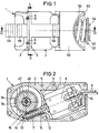
- the motor-gear unit shown in the drawing has a housing which consists of a lower housing part 1 and an upper housing part 2 and is made of a weldable thermoplastic, the two housing parts being provided with flanges 3, 4 which can be put together.
- the flange 3 facing the lower housing part 1 is provided with centering holes 5, while pins 6 assigned to these centering holes 5 are formed on the flange 4 of the upper housing part 2, which are inserted into the centering holes 5 and welded after assembly and assembly of the lower housing part 1 and the upper housing part 2 are, so that they also serve for the firm connection of the lower housing part 1 and upper housing part 2.
- the housing 1, 2 is provided with a receiving space 7 for an electric motor 8, the electrical supply lines 9 of which are led through an opening 10 into the receiving space 7.
- the motor 8 is reversible in the direction of rotation, that is to say it can be driven in both possible directions of rotation.
- the electric motor 8 lies in the receiving space 7 against stops 11 formed in the housing, and is therefore already aligned in its position when it is inserted into the lower housing part 1.
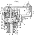
- the electric motor 8 is provided with a shaft 12 projecting freely from the housing 1, 2, the free end 13 of which is removed from the electric motor 8 is supported in a bearing shell 14 formed in the lower housing part 1.
- a plastic cylindrical worm 15 of a worm gear 16 is mounted such that it cannot be rotated relative to the shaft 12, for example by a press fit.
- the helical toothing 17 of the worm 15 engages in a correspondingly adapted toothing 18 of a worm wheel 19, which together with the worm 15 forms the worm gear 16.
- a planetary gear 20 is arranged downstream of the worm gear 16.
- the planetary gear 20 has a sun gear 21 which is formed in one piece with the worm gear 19 and is connected to it in a rotationally fixed manner, in whose external toothing 22 three planet gears 23, only one of which is shown, engage with their corresponding external toothing 24.
- the planet gears 23 are supported on a ring gear 25, which is provided with an internal toothing 26 in which the respective external toothing 24 of the planet gears 23 engages.
- the ring gear 25 is non-rotatable relative to the housing 1, 2, for which purpose it is provided with projections 27 on its outer circumference, which engage in adapted recesses 28 in the housing 1, 2.
- the planet gears 23 are rotatably mounted on bearing journals 29 of a web lower part 30 and are thereby held at equal angular distances from one another.
- the planet gears 23 are each formed in one piece with a gear 32 of a ring gear 33.
- the external teeth of these gears 32 of the ring gear 33 engage in an internal toothing 35 of an output ring gear 36 of the ring gear 33.
- a bearing journal 37 of an upper web part 38 engages in each of the gear wheels 32.
- the lower part 30 of the web and the upper part 38 of the web are connected to one another by means of receiving openings 39 formed on the lower part 30 of the web and connecting pins 40 engaging in them, formed on the upper part 38 of the web, to form a housing-like web.
- the output ring gear 36 has a cylindrical bearing section 41 formed in one piece with it, which is mounted radially to the common axis of rotation 42 of the worm wheel 19, the planetary gear 20 and the ring gear 33 in a bearing shell 43 which is formed on the upper housing part 3.
- the output ring gear 36 is further fixed in the direction of the axis of rotation 42 relative to the upper housing part 2 by stop surfaces 44, 45 which extend radially to the axis of rotation 42 and which prevent the rotation of the Output ring gear 36 does not hinder, but limit the play, ie the displaceability of the ring gear 36 in the direction of the axis of rotation 42 to about 0.1 mm.
- the worm gear 16, the planetary gear 20 and the ring gear 33 form a reduction gear.
- the worm wheel 19 is mounted on a continuous cylindrical axis 46 made of steel, one end of which is held in a receptacle 47 in the lower housing part 1 with a press fit, that is to say non-rotatable relative to the lower housing part 1.
- the other end of the axis 46 is supported largely without play in a cylindrical recess 48 of the output ring gear 36 which is concentric with the axis of rotation 42 radially to the axis of rotation 42, but the non-rotatable axis 46 does not hinder the rotation of the output ring gear 46.
- the worm wheel 19 is freely rotatable on the axis 46 and is supported in the direction of the axis of rotation 42 against the end face 49 of the receptacle 47 in the direction of the lower housing part 1. In the direction of the output ring gear 36, it is axially supported on the ring gear 25 of the planetary gear 20.
- the output ring gear 36 which is made entirely of metal, for example cast zinc, has an essentially cylindrical output section 50 which adjoins the bearing section 41 and which has at least one, but preferably two longitudinal grooves running diametrically opposite to the axis of rotation 42 and parallel to the axis of rotation 42 51 has.
- a friction ring 52 of a slip clutch 53 Arranged on the output section 50 is a friction ring 52 of a slip clutch 53, which engages with a protrusion 54 in each of the longitudinal grooves 51, as a result of which a rotationally fixed connection between the output ring gear 36 and the friction ring 52 is produced.
- the friction ring 52 lies against an annular collar 55 at the transition from the bearing section 41 to the driven section 51 in the direction of the axis of rotation 42. It forms the abutment surface 45 already mentioned above.
- the output section 50 is surrounded by an output pivoting part 56 which has a recess 57 running parallel to the axis of rotation 42, into which a bolt (not shown) of a part to be pivoted can engage.
- the output pivoting part 56 has a friction surface 58 which bears on a friction surface 59 of the friction ring 52. Both friction surfaces 58, 59 are frustoconical and taper away from the upper housing part 2 at a half cone opening angle a. 7 ° ⁇ a ⁇ 15 ° and preferably a ⁇ 10 °.
- the output pivoting part 56 is pressed in the direction of the friction ring 52 by means of a prestressed helical compression spring 60, only the friction surfaces 58, 59 of the pivoting part 56 and the friction ring 52 abutting one another.
- the above-mentioned slip clutch 53 is thus formed, the slip moment of which is caused by the friction coefficient between the friction surface 59 of the friction ring 52 and the friction surface 58 of the swivel part 56 and by the force, which is normal - that is, perpendicular - to the friction surfaces 58, 59 the average diameter d of the friction surface 58, 59 is determined.
- the force acting perpendicular to them between the friction surfaces 58, 59 is greater for a given force of the compression spring 60 in the direction of the axis of rotation 42, the smaller the half cone opening angle ⁇ of the friction surfaces 58, 59.
- the force acting perpendicularly to the friction surfaces 58, 59 between them is in any case several times greater, that is to say the force of the compression spring 60.
- the friction ring 52 is made of metal, for example of cast zinc, while the Output swivel part 56 consists of a common plastic.
- the helical compression spring 60 bears against the output swivel part 56 with the interposition of an annular disk serving as a pressure disk 61.
- This thrust washer 61 is also fixed in the longitudinal grooves 51 by means of projections 54 to the output ring gear 36.
- the frictional torque acting between the thrust washer 61 and the swivel part 56 is smaller than the slip torque of the slip clutch 53 by at least the quotient 10.
- the compression spring 60 also lies in the region of the free end 64 of the output section 50 against another ring disk serving as an abutment 62, which is connected to the output section 50 by means of a bayonet catch 63 is locked.
- the two washers are made of metal, for example steel. They are of identical design and have projections 54 which are adapted to the longitudinal grooves 51 and which are identical in cross section to the projections 54 on the friction ring 52.
- a partial circumferential groove 65 is formed on the output section 50 thereof, which has a longitudinal groove on one side 51 leads out.
- Each partial circumferential groove 65 is thus open at one end 66 to form a longitudinal groove 51. In contrast, it is closed at the other end 67 to the other longitudinal groove 51.
- Each partial circumferential groove 65 has a recess 68 directed towards the free end 64, which corresponds to the projections 54 on the abutment ring disk 62.
- All gearwheels with the exception of the output ring gear 36, are made of plastic and can be rotated about the axis of rotation 42 or an axis parallel thereto.
- the assembly takes place in such a way that the electric motor 8 is inserted into the receiving space 7 in the lower housing part 1 and the lines 9 are led out through the opening 10.
- the free end 13 of the shaft 12 already provided with the worm 15 is inserted into the bearing shell 14.
- the axis 46 is pressed into the receptacle 47.
- the worm wheel 19 of the planetary gear 20 is pushed onto the axis until it comes to rest on the end face 49 of the receptacle 47.
- the ring gear 25 of the planetary gear 20 is then pushed onto the axis.
- the preassembled unit consisting of the lower web part 30, planet gears 23 with gear wheels 32 and the upper web part 38 is inserted into the ring gear 25 such that the external toothings 24 of the planet wheels 23 come into engagement with the internal toothing 26 of the ring gear 25.
- the output ring gear is pushed onto the axis 46, at the same time the external toothing 34 of the gearwheels 32 engaging with the internal toothing 35 of the output ring gear 36.
- the axis 46 is in the recess 48 of the output ring gear 36 and radially supported to the axis of rotation 42.
- the upper housing part 2 is placed on the lower housing part 1, the output section 50 being passed through the bearing shell 43.
- the pins 6 of the upper housing part 2 engage in the centering holes 5 of the lower housing part 1 and are welded to it, for example by ultrasound.
- the output ring gear 36 is now mounted radially with its bearing section 41 in the bearing shell 43 of the upper housing part 2. Subsequently, the friction ring 52 of the slip clutch 53 is pushed onto the output section 50 and then the output pivoting part 56 is placed so that the two friction surfaces 58, 59 abut one another. Then the thrust washer 61 is pushed onto the driven section 50 and the helical compression spring 60 is also placed onto the driven section 50.
- the helical compression spring 60 is then pretensioned in the direction of the friction ring 52 and the abutment washer 62 is locked to the driven section 50 by means of the bayonet catch 63.
- the abutment washer 62 is pushed onto the free shaft 64 of the output section 50 by compressing the compression spring 60 and, after reaching the partial circumferential grooves 65, is rotated such that the projections 54 enter these partial circumferential grooves 65 until they stop at closed end 67. If the abutment washer 62 is now relieved, it is pushed back towards the free end 64 until its projections 54 come into contact with the recesses 68.
- the abutment ring disk 62 is then non-rotatable with respect to the driven section 50, and therefore cannot be released simply by turning, regardless of the direction in which the driven section 50 with the driven pivot part 56 is rotated about the axis of rotation 42.
- the fully assembled motor-gear unit can be mounted for appropriate use by means of fastening openings 69 formed on the housing 1, 2.
Landscapes
- Engineering & Computer Science (AREA)
- General Engineering & Computer Science (AREA)
- Mechanical Engineering (AREA)
- Power Engineering (AREA)
- Multimedia (AREA)
- Gear Transmission (AREA)
- Connection Of Motors, Electrical Generators, Mechanical Devices, And The Like (AREA)
- Mechanical Operated Clutches (AREA)
Applications Claiming Priority (2)
| Application Number | Priority Date | Filing Date | Title |
|---|---|---|---|
| DE19615002 | 1996-04-16 | ||
| DE19615002A DE19615002A1 (de) | 1996-04-16 | 1996-04-16 | Getriebe-Einheit |
Publications (1)
| Publication Number | Publication Date |
|---|---|
| EP0802084A1 true EP0802084A1 (fr) | 1997-10-22 |
Family
ID=7791426
Family Applications (1)
| Application Number | Title | Priority Date | Filing Date |
|---|---|---|---|
| EP97104374A Withdrawn EP0802084A1 (fr) | 1996-04-16 | 1997-03-14 | Ensemble de transmission |
Country Status (4)
| Country | Link |
|---|---|
| US (1) | US6283863B1 (fr) |
| EP (1) | EP0802084A1 (fr) |
| DE (1) | DE19615002A1 (fr) |
| MX (1) | MX9702765A (fr) |
Families Citing this family (13)
| Publication number | Priority date | Publication date | Assignee | Title |
|---|---|---|---|---|
| DE19953484C2 (de) * | 1999-11-06 | 2002-03-07 | Oechsler Ag | Ausrastbarer Schwenkantrieb |
| JP3482400B2 (ja) * | 2001-04-18 | 2003-12-22 | 川崎重工業株式会社 | 不整地走行車の動力伝達装置 |
| DE10141240A1 (de) * | 2001-08-23 | 2003-03-06 | Trw Repa Gmbh | Gurtaufroller mit Getriebemotor |
| DE10251057B4 (de) * | 2002-11-02 | 2006-06-22 | Julius Cronenberg Offene Handelsgesellschaft | Aufrollvorrichtung für Gurte oder dergleichen |
| WO2005068257A1 (fr) * | 2004-01-13 | 2005-07-28 | Truck-Lite Co., Inc. | Ensemble embrayage pour retroviseur liberable |
| DE102005012652A1 (de) * | 2005-03-18 | 2006-10-05 | Ejot Gmbh & Co. Kg | Rutschkupplung |
| US7966904B2 (en) | 2006-05-05 | 2011-06-28 | Questek Manufacturing Corporation | Low axial play drive system |
| JP5501746B2 (ja) * | 2009-12-11 | 2014-05-28 | 株式会社村上開明堂 | ドアミラーおよびその組み付け方法 |
| DE102013220233A1 (de) * | 2013-10-08 | 2015-04-09 | Robert Bosch Gmbh | Werkzeugmaschinensystem |
| DE102015218377A1 (de) | 2015-09-24 | 2017-03-30 | Schaeffler Technologies AG & Co. KG | Hohlradgetriebe |
| JP6618415B2 (ja) * | 2016-04-08 | 2019-12-11 | 株式会社東海理化電機製作所 | 車両用視認装置 |
| NL2018838B1 (nl) | 2017-05-03 | 2018-11-14 | Mci Mirror Controls Int Netherlands B V | Verstelinstrument en werkwijze |
| DE102017129186B4 (de) * | 2017-12-07 | 2021-07-01 | Motherson Innovations Company Limited | Rückblickvorrichtung für ein Kraftfahrzeug, Montageverfahren dafür und Kraftfahrzeug mit einer Rückblickvorrichtung |
Citations (8)
| Publication number | Priority date | Publication date | Assignee | Title |
|---|---|---|---|---|
| GB139648A (en) * | 1919-04-02 | 1920-03-11 | William Turton | Improvements in self releasing holders for screw cutting taps or dies |
| DE468386C (de) * | 1927-04-22 | 1928-11-12 | Henri Bertauld | Maschine zur Befoerderung von Korn |
| US2569144A (en) * | 1946-11-21 | 1951-09-25 | T M K Corp | Overload release friction coupling |
| GB2054496A (en) * | 1979-08-04 | 1981-02-18 | Kienzle Uhrenfabriken Gmbh | Remotely controlled rear-view mirrors |
| GB2064682A (en) * | 1979-12-12 | 1981-06-17 | Hilti Ag | Friction clutch for transmitting limited torque |
| FR2509236A1 (fr) * | 1981-07-09 | 1983-01-14 | Berex | Dispositif de transmission pour un vehicule a plusieurs essieux moteurs |
| US4880407A (en) * | 1988-02-16 | 1989-11-14 | Custom Products Corporation | Cone clutch |
| WO1991004172A1 (fr) * | 1989-09-14 | 1991-04-04 | Iku Holding Montfoort B.V. | Mecanisme pivotant pour logement de retroviseur de vehicule |
Family Cites Families (33)
| Publication number | Priority date | Publication date | Assignee | Title |
|---|---|---|---|---|
| DE7627888U1 (fr) * | 1900-01-01 | Julius Bauser Kg, Kontrolluhrenfabrik, 7241 Empfingen | ||
| US2901912A (en) * | 1958-01-02 | 1959-09-01 | Bendix Aviat Corp | Engine starter gearing |
| US2974503A (en) * | 1958-02-21 | 1961-03-14 | Alan R Newton | Torque limiting device |
| US3265362A (en) | 1964-03-02 | 1966-08-09 | Warren E Moody | Hoisting devices |
| US3648483A (en) * | 1970-06-01 | 1972-03-14 | Gen Electric | Overload friction coupling |
| JPS5511210Y2 (fr) * | 1974-04-18 | 1980-03-11 | ||
| IT1026359B (it) * | 1975-01-15 | 1978-09-20 | Spem Srl | Dispositivo di frizione a carico constante specialmente adatto per l applicazione nei registratori a nastro |
| JPS6047130B2 (ja) | 1975-08-14 | 1985-10-19 | 市光工業株式会社 | 栗両用後写鏡 |
| US4133344A (en) | 1976-06-10 | 1979-01-09 | The Toro Company | Power transmission for self-propelled irrigation system |
| DE2820541C2 (de) * | 1978-05-11 | 1986-10-09 | Bernhard Dipl.-Wirtsch.-Ing. 3002 Wedemark Mittelhäuser | Außenrückblickspiegel für Kraftfahrzeuge |
| DE2846586A1 (de) * | 1978-10-26 | 1980-05-08 | Kienzle Uhrenfabriken Gmbh | Verstellvorrichtung fuer kfz-aussenrueckblickspiegel |
| DE3013009A1 (de) * | 1980-04-03 | 1981-10-08 | Gustav Magenwirth Gmbh & Co, 7432 Urach | Vorrichtung zum antrieb eines kraftfahrzeugspiegels |
| DE3412338C2 (de) * | 1983-09-21 | 1986-07-31 | Rhein-Getriebe Gmbh, 4005 Meerbusch | Schneckengetriebe |
| DE3434905A1 (de) | 1984-09-22 | 1986-04-03 | SWF Auto-Electric GmbH, 7120 Bietigheim-Bissingen | Antriebseinheit, insbesondere zum verstellen von fensterscheiben, schiebedaechern, sitzen und aehnlichen kraftfahrzeugteilen |
| US4699024A (en) | 1985-05-21 | 1987-10-13 | Aisin Seiki Kabushiki Kaisha | Device for adjusting the angular position of one member relative to another |
| US4641887A (en) | 1985-09-16 | 1987-02-10 | Keiper Recaro Incorporated | Planetary seat back adjuster |
| US4660247A (en) * | 1985-12-31 | 1987-04-28 | Whirlpool Corporation | Temperature limiting system for a spring loaded torque limiting clutch |
| DE3741615A1 (de) | 1987-12-09 | 1989-06-22 | Reitter & Schefenacker Kg | Elektrischer motorantrieb fuer fensterheber von kraftfahrzeugen |
| US4921083A (en) | 1989-02-28 | 1990-05-01 | Square D Company | Clutch module with predetermined torque |
| DE3914334C2 (de) * | 1989-04-29 | 1994-08-04 | Kienzle Uhrenfabriken Gmbh | Verstellvorrichtung für einen KFZ-Außenspiegel |
| JP2515645Y2 (ja) | 1989-11-21 | 1996-10-30 | アスモ 株式会社 | 減速機付モ−タ |
| IT220513Z2 (it) * | 1990-05-15 | 1993-09-24 | Gilardini Spa | Specchio retrovisore per un veicolo. |
| JPH0689788B2 (ja) * | 1990-05-30 | 1994-11-14 | 株式会社椿本エマソン | スリップクラッチ |
| JPH0463738A (ja) | 1990-07-04 | 1992-02-28 | Ichikoh Ind Ltd | 電動ステー格納式ミラー装置 |
| DE4119748C2 (de) * | 1991-06-15 | 1994-06-09 | Luchtenberg Gmbh & Co | Abklappbarer Rückspiegel |
| IT1252140B (it) * | 1991-11-29 | 1995-06-05 | Commer Spa | Dispositivo per la rotazione controllata di uno specchietto retrovisore esterno |
| JPH05222245A (ja) * | 1992-02-10 | 1993-08-31 | Tokai Carbon Co Ltd | ゴム組成物 |
| NL9202266A (nl) | 1992-12-24 | 1994-07-18 | Iku Holding Montfoort Bv | Spiegelinklapmechanisme, en voertuig voorzien van een dergelijk spiegelinklapmechanisme. |
| DE4311355C2 (de) * | 1993-04-06 | 1995-01-26 | Stephan Werke Gmbh & Co | Schneckengetriebe |
| DE4324876C2 (de) * | 1993-07-23 | 1995-06-01 | Ims Morat Soehne Gmbh | Getriebe und dessen Verwendung |
| JPH07195979A (ja) * | 1993-12-28 | 1995-08-01 | Sakae Riken Kogyo Kk | 電動可倒式ミラー装置 |
| JP3423411B2 (ja) | 1994-06-09 | 2003-07-07 | 株式会社リコー | ヘリカルスパイラルカムの製造方法 |
| JP3323686B2 (ja) | 1995-01-10 | 2002-09-09 | アスモ株式会社 | 移動体の位置検出装置 |
-
1996
- 1996-04-16 DE DE19615002A patent/DE19615002A1/de not_active Withdrawn
-
1997
- 1997-03-14 EP EP97104374A patent/EP0802084A1/fr not_active Withdrawn
- 1997-04-04 US US08/832,936 patent/US6283863B1/en not_active Expired - Lifetime
- 1997-04-16 MX MX9702765A patent/MX9702765A/es unknown
Patent Citations (8)
| Publication number | Priority date | Publication date | Assignee | Title |
|---|---|---|---|---|
| GB139648A (en) * | 1919-04-02 | 1920-03-11 | William Turton | Improvements in self releasing holders for screw cutting taps or dies |
| DE468386C (de) * | 1927-04-22 | 1928-11-12 | Henri Bertauld | Maschine zur Befoerderung von Korn |
| US2569144A (en) * | 1946-11-21 | 1951-09-25 | T M K Corp | Overload release friction coupling |
| GB2054496A (en) * | 1979-08-04 | 1981-02-18 | Kienzle Uhrenfabriken Gmbh | Remotely controlled rear-view mirrors |
| GB2064682A (en) * | 1979-12-12 | 1981-06-17 | Hilti Ag | Friction clutch for transmitting limited torque |
| FR2509236A1 (fr) * | 1981-07-09 | 1983-01-14 | Berex | Dispositif de transmission pour un vehicule a plusieurs essieux moteurs |
| US4880407A (en) * | 1988-02-16 | 1989-11-14 | Custom Products Corporation | Cone clutch |
| WO1991004172A1 (fr) * | 1989-09-14 | 1991-04-04 | Iku Holding Montfoort B.V. | Mecanisme pivotant pour logement de retroviseur de vehicule |
Also Published As
| Publication number | Publication date |
|---|---|
| DE19615002A1 (de) | 1997-10-23 |
| MX9702765A (es) | 1998-04-30 |
| US6283863B1 (en) | 2001-09-04 |
Similar Documents
| Publication | Publication Date | Title |
|---|---|---|
| DE3510605C2 (fr) | ||
| EP2611647A1 (fr) | Commande de réglage pour des dispositifs de réglage d'un siège de véhicule automobile | |
| EP1989096B1 (fr) | Engrenage hélicoïdal pour une direction à crémaillère | |
| DE3019524A1 (de) | Kompaktes zahnradgetriebe fuer einen fensterbetaetiger | |
| EP0802084A1 (fr) | Ensemble de transmission | |
| EP0802348B1 (fr) | Ensemble de transmission | |
| DE102019209470A1 (de) | Parksperrenanordnung mit Parksperrenrad und Torsionsdämpfer | |
| DE102004008538B4 (de) | Differential mit einer Bolzenbefestigungsbaugruppe | |
| DE3700678A1 (de) | Scheibenwischermotor | |
| DE69812446T2 (de) | Anlasser für Motorfahrzeug mit epizyklischen Untersetzungsgetriebe und Momentbegrenzer | |
| DE4302726C2 (de) | Zahnwellenverbindung und Verfahren zur Herstellung einer Zahnwellenverbindung | |
| DE19945255A1 (de) | Radlagerung, insbesondere für nichtangetriebene Fahrzeugachsen | |
| EP1303430A1 (fr) | Dispositif d'essuie-glace | |
| DE29923786U1 (de) | Antriebsvorrichtung für einen verstellbaren Rückblickspiegel mit einem selbstkalibrierenden Potentiometer | |
| WO2015172968A1 (fr) | Dispositif pour empêcher le détachement intempestif d'un élément de serrage | |
| WO2022083982A1 (fr) | Unité d'engrenage à excentrique pour un générateur de force de freinage, et générateur de force de freinage | |
| EP0918931B1 (fr) | Groupe motopompe electrique | |
| EP0989655A2 (fr) | Entraínement linéaire à moteur électrique | |
| DE69508230T2 (de) | Drehschwingungsdämpfer | |
| EP3765758B1 (fr) | Engrenage à vis sans fin comprenant un palier pivotant comprenant un axe de pivotement défini | |
| DE4308975C2 (de) | Wellen-Naben-Verbindung | |
| DE3045560C2 (de) | Antriebsvorrichtung für Scheibenwischer an Kraftfahrzeugen | |
| DE102004044753B4 (de) | Neigungsverstellbeschlag für die Rückenlehne eines Kraftfahrzeugsitzes | |
| DE102021211648B4 (de) | Welle-Nabe-Verbindung | |
| DE19650716C1 (de) | Exzentergetriebe |
Legal Events
| Date | Code | Title | Description |
|---|---|---|---|
| PUAI | Public reference made under article 153(3) epc to a published international application that has entered the european phase |
Free format text: ORIGINAL CODE: 0009012 |
|
| AK | Designated contracting states |
Kind code of ref document: A1 Designated state(s): DE ES FR GB IT SE |
|
| 17P | Request for examination filed |
Effective date: 19980318 |
|
| 17Q | First examination report despatched |
Effective date: 19990921 |
|
| STAA | Information on the status of an ep patent application or granted ep patent |
Free format text: STATUS: THE APPLICATION IS DEEMED TO BE WITHDRAWN |
|
| 18D | Application deemed to be withdrawn |
Effective date: 20010317 |